Home
doorbell wire
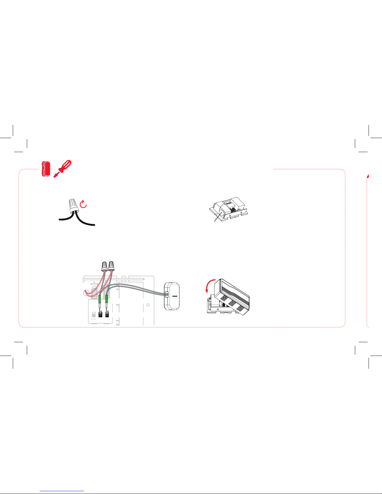
Wire nut
Twist
Wire
lead
OPTION B: If your home’s doorbell power wires are NOT long
enough.
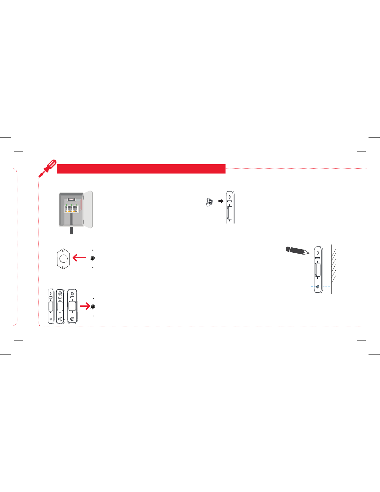
Turn on power to your doorbell’s circuit
Turn the circuit that powers your
doorbell back on.
10
Conrm the video doorbell has power
The indicator around the doorbell’s call
button ashes when it has power (rst
red, then blue).
If the indicator is ashing: Go to the
next step.
If the indicator is NOT ashing: First,
check the connections on the back of
the video doorbell. Then, press and hold
the reset button on the front of the video
doorbell for 4 seconds, until the doorbell
says “reset successful.”
11
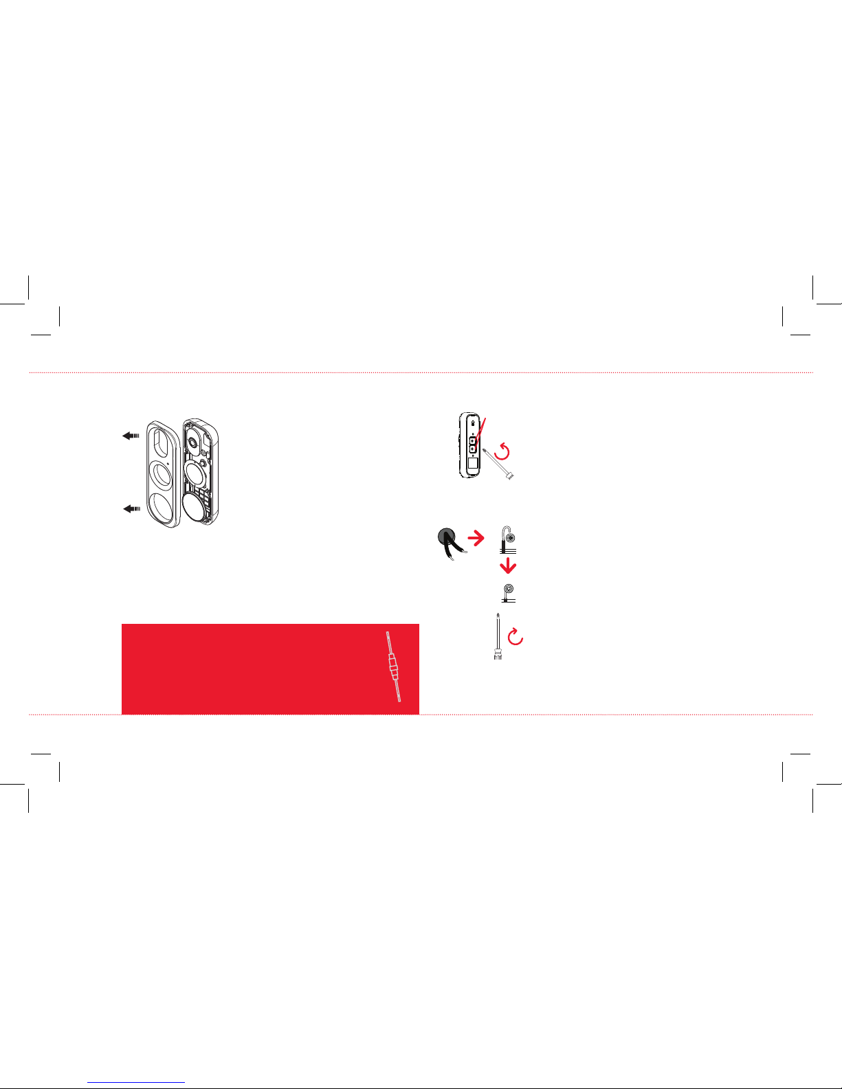
Use the screwdriver provided in this package
to loosen the terminal screws on the back of
the video doorbell.
Loosen
Doorbell camera back
Terminals
Place the terminal of each provided wire lead
completely under each terminal screw. Then
retighten both terminal screws.
Put the ends of one wire lead and one home
doorbell wire together and insert them into
a wire nut. Then twist the wire nut until you
feel tension. Repeat with the other wire lead,
home doorbell wire, and wire nut.
CONNECT & MOUNT THE VIDEO DOORBELL (continued)
RESISTOR INSTRUCTIONS
(IF YOU DON’T HAVE A CHIME BOX)
To install the resistor provided: Remove the sheaths
covering the ends of the resistor. Put one end of
the resistor together with one of the wire leads
connected to the video doorbell. Use one of the
provided wire nuts to twist these ends together.
Connect the other end of the resistor to your home
doorbell wire following the instructions below.