RCA DRC8320N User manual


WARNING
To reduce the risk of fire or shock hazard, do not expose
this DVD Recorder to rain or moisture.
RISK OF ELECTRIC
SHOCK DO NOT OPEN
This symbol indicates that this product incorporates double
insulation between hazardous mains voltage and user
accessible parts.
This symbol indicates “dangerous
voltage” inside the product that
presents a risk of electric shock or
personal injury.
This symbol indicates
important instructions
accompanying the product.
FCC INFORMATION
This equipment has been tested and found to comply with the limits for a Class B digital device,
pursuant to Part 15 of the FCC rules.These limits are designed to provide reasonable protection
against harmful interference in a residential installation.This equipment generates, uses and can radiate
radio frequency energy and, if not installed and used in accordance with the instructions, may cause
harmful interference to radio communications. However, there is no guarantee that interference
will not occur in a particular installation. If this equipment does cause harmful interference to radio
or television reception, which can be determined by turning the equipment off and on, the user is
encouraged to try to correct the interference by one or more of the following measures.
• Reorient or relocate the receiving antenna.
• Increase the separation between the equipment and receiver.
• Connect this equipment into an outlet on a circuit different from that to which the receiver is
connected.
• Consult the dealer or an experienced radio/TV technician for help.
This class B digital apparatus meets all requirements of the Canadian Interference – Causing Equipment
Regulations.This class B digital apparatus complies with Canadian CES-003.
Cet appareil numérique de la class B est conforme á la norme du NMB-003 du Canada.
Refer to the identification/rating label located on the back panel of your product for its proper
operating voltage.
Product Registration
Please fill out the product registration card and return it immediately. Returning the product registration
card allows us to contact you if needed.
Keep your sales receipt to obtain warranty parts and service and for proof of purchase.Attach it here and
record the serial and model numbers in case you need them.The numbers are located on the back of the
DVD Recorder.
Model No. __________________________ Serial No. __________________________
Purchase Date: ___________________________________________________________
Dealer/Address/Phone: ____________________________________________________
The AC power cord is polarized (one blade is wider than the other) and
only fits into AC outlets one way. If the plug won’t go into the outlet
completely, turn the plug over and try to insert it the other way. If it
still won’t fit, contact a qualified electrician to change the outlet or use a
different one. Do not attempt to bypass this safety feature.
Ventilation:
You must adequately ventilate the product. Make sure there is adequate space around the DVD
Recorder to provide proper air flow for ventilation. See diagram.
CAUTION
THIS PRODUCT UTILIZES A LASER. USE OF
CONTROLS OR ADJUSTMENTS OR PERFORMANCE
OF PROCEDURES OTHER THAN THOSE SPECIFIED
HEREIN MAY RESULT IN HAZARDOUS RADIATION
EXPOSURE. DO NOT OPEN COVERS AND DO NOT
REPAIR YOURSELF. REFER SERVICING TO QUALIFIED
PERSONNEL.
CAUTION
FCC Regulations state that unauthorized changes or
modifications to this equipment may void the user’s
authority to operate it.
Note:
This DVD Recorder is designed and manufactured to
respond to the Region Management Information. If the
Region number of a DVD disc does not correspond to the
Region number of this DVD Recorder this DVD Recorder
cannot play the disc.The Region number for this DVD
Recorder is Region No 1.
Note:
This device is protected by U.S. patent numbers 4,631,603
and 4,577,216 and 4,819,098 and other intellectual property
rights.The use of Macrovision’s copy protection technology
in the device must be authorized by Macrovision and is
intended for home and other limited pay-per-view uses only,
unless otherwise authorized in writing by Macrovision.
Reverse engineering or disassembly is prohibited.
The apparatus shall not be exposed to dripping or splashing
and that no objects filled with liquids, such as vases, shall be
placed on the apparatus.
Important Information
IMPORTANT: The power cord can be
unplugged to turn off the main power to the
unit. It should also be easily accessible in an
emergency.

Table of Contents
Graphics contained within this publication are for representation only. 1
Types of Discs ................................................................... 2
Things to consider before you connect.......................... 2
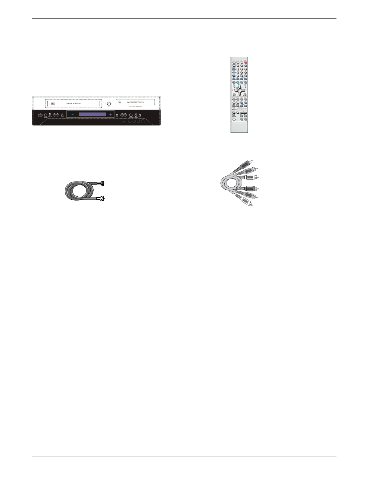
Unpack the Box................................................................ 3
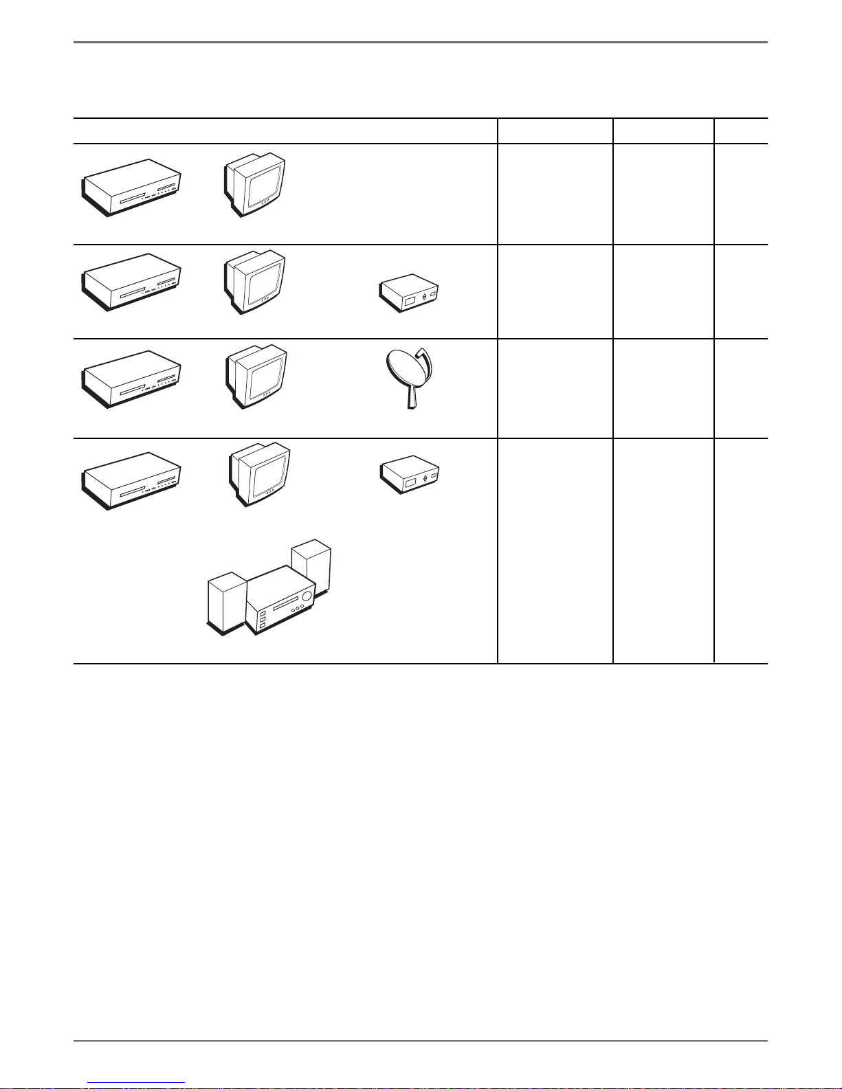
Choose Your Connection ................................................. 4
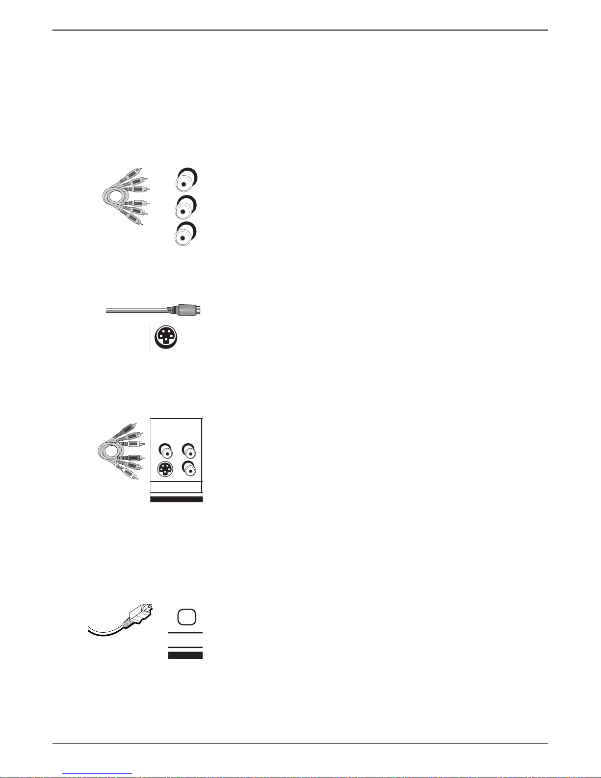
Explanation of Input Jacks and Cables........................... 5
Back of the DVD/VCR....................................................... 6
Explanation of Jacks .................................................. 6
Front of the DVD/VCR...................................................... 8
Display of the DVD/VCR .................................................. 9
Connection: DVD/VCR + TV ........................................... 11
Connection: DVD/VCR + TV + Basic Cable Box............. 13
Connection: DVD/VCR + TV + Satellite Receiver.......... 15
Connection: DVD/VCR + TV + Basic Cable Box +
Audio Receiver ........................................................ 17
Install Batteries in the Remote...................................... 19
Point the Remote in the Right Direction................ 19
Turn on the TV and DVD/VCR ....................................... 19
Complete the General Setup ........................................ 19
Setting the Clock ..................................................... 20
Setting the Signal Type............................................ 20
Searching for Channels ........................................... 20
What to Expect............................................................... 21
Turn on the DVD recorder to Watch TV ................. 21
Discs for Recording .................................................. 21
Next Steps ...................................................................... 22
Explanation of the Remote Control Buttons ............... 23
Using the Remote’s Features......................................... 24
Understanding the INPUT button........................... 24
The Channel Banner....................................................... 24
DVD Recording ............................................................... 25
DISCS THAT YOU CAN USE FOR RECORDING ......... 25
Express Recording.................................................... 25
Timer Recordings ........................................................... 25
Setting Up a Timer Recording .......................... 25
Watching one channel while you record another
channel (cable with no cable box or off-air
antenna only) .......................................................... 26
Copying a video cassette tape to a DVD disc .............. 26
Recording from a DV Camcorder .................................. 26
DVD Playback ................................................................. 26
Editing DVD Discs........................................................... 27
VCR Basics....................................................................... 28
Basic Playback .......................................................... 28
Tape Eject ................................................................... 28
Basic Recording........................................................ 28
VCR Recording................................................................ 28
Express Recording ............................................................. 29
Watching one channel while you record another
channel (cable with no cable box or
antenna only) ........................................................... 29
Timer Recordings ........................................................... 29
Regional Coding............................................................. 30
Types of discs you can play ........................................... 30
How to Load and Play Discs.......................................... 30
Using Different Menus .................................................. 31
Search Options ............................................................... 31
Playback Options ........................................................... 31
Using the On-screen Info Display ................................. 32
Title Icon................................................................... 32
Chapter Icon............................................................. 32
Time ......................................................................... 33
Audio Icon................................................................ 33
Subtitles Icon............................................................ 33
Repeat Icon .............................................................. 33
AB Repeat ................................................................ 34
Random Icon ............................................................ 34
Language Icon ......................................................... 34
Playing Discs You Recorded (DVD±R and DVD±RW) ... 34
Playing mp3, WMA, JPEG les ...................................... 35
The File Browser ...................................................... 35
Navigating and Viewing the Files .................... 36
Creating an mp3 Disc on Your Computer .............. 36
The DVD/VCR Menu System.......................................... 37
Recording ................................................................. 37
Recording Quality ............................................. 37
Chapter Marker ................................................. 37
Timer Recording ................................................ 37
Overwrite........................................................... 37
Audio/Video Menu .................................................. 38
Dynamic Range Control .................................... 38
Scan Mode (Progressive Scan)................................. 39
Disc Menu................................................................. 39
Rating................................................................. 39
Change Password .............................................. 39
Parental Control (Setting the Ratings)............. 39
Angle Mark........................................................ 40
General Menu .......................................................... 40
The TVGuardian Menu ............................................ 40
How it works ..................................................... 40
TVGuardian Mode............................................. 40
Word Subset Filtering ....................................... 40
TV Menu................................................................... 41
TV Signal ........................................................... 41
Automatic Search .............................................. 41
CH Skip (Channel Skip)...................................... 41
CH Fine Tune (Channel Fine Tune) ................... 41
MTS Setting ....................................................... 41
Troubleshooting............................................................. 42
Handling Cautions ......................................................... 45
Maintenance of Cabinet................................................ 45

Graphics contained within this publication are for representation only.
2
Chapter 1: Connections and Setup
Types of Discs
DISCS YOU CAN USE FOR RECORDING
DVD±R 2.4x, 4x, or 8x, and 16x ONLY;
DVD±RW 2.4x and 4x ONLY.
IMPORTANT: It is NOT possible to record content that is copy-protected. This is usually true for most pre-
recorded DVD discs and most pre-recorded VHS tapes.
TYPES OF DISCS YOU CAN PLAY
•
DVD discs –
DVD movie discs (DVD-ROM); DVD+R; DVD+RW; DVD-RW (must be recorded using video mode
or VM); DVD-R (must be recorded using video mode or VM and must be finalized). DVD audio discs are not
compatible.
•
CDs (Audio CDs, CD-R, CD-RW, mp3 discs) –
Audio CDs contain musical or sound content only. mp3 discs are CDs
(CD-R or CD-RW) that contain mp3 files. This product also plays CDs that contain JPEG and WMA files and
Multisession CDs.
•
Video CD (VCD) –
Like DVD video discs, VCDs contain picture and sound content. The difference is the amount
of information that can be stored on the disc. VCDs typically have lower picture and sound quality than DVD discs.
You must use DVD±R or DVD±RW discs to record on your DVD recorder not VCDs.
Things to consider before you connect
Protect components from overheating
• Don’t block ventilation holes on any of the components. Arrange the components so that air can circulate freely.
• Don’t stack components.
• When you place components in a stand, make sure you allow adequate ventilation.
• If you connect an audio receiver or amplifier, place it on the top shelf.
Position cables properly to avoid audio interference
• Insert each cable firmly into the designated jack.
• If you place components above the TV, route all cables down the side of the back of the TV instead of straight down the middle of the back of the
TV.
Some discs may not
be compatible due to
laser pickup and disc
design.
DVD+Rewritable
DVD+R

Graphics contained within this publication are for representation only. 3
Chapter 1: Connections and Setup
DVD/VCR recorder Remote control
and batteries
1 set of audio video cables
RF Coaxial cable
Connection Pictures
Audio/video cables are usually bundled together. For better visibility, the connection pictures in this book show each cable separately (audio left, audio
right, and video). Graphics contained within this publication are for representation only.
Unpack the Box
Your DVD/VCR came with the following items:

Graphics contained within this publication are for representation only.
4
Chapter 1: Connections and Setup
Choose Your Connection
There are several ways to connect your DVD recorder. Please use the following chart to determine which connection is best for you. Turn to the
appropriate page for specific instructions.
• Coaxial
• Audio/video
• S-Video
• Component Video
Components Cables Needed Connection Go to
Satellite Receiver
TV
Cable Box
TV
TV
TV page 10
• Coaxial
• Audio/video
• S-Video
• Component Video
TV + cable
box
page 12
• Coaxial
• Audio/video
• S-Video
• Component Video
TV +
satellite
receiver
page 14
To achieve enhanced picture
quality, use an S-Video cable
or component video cables to
connect your DVD/VCR recorder
to your TV if your TV has
corresponding jacks available.
TV
• Coaxial
• Audio/video
• S-Video
• Digital Audio
• Component Video
TV + cable
box + audio
receiver
Cable Box
page 16
Audio Receiver
DVD/VCR
STOP
CH+/SKIP+
CH-/SKIP-FWD
REVPLAY/PAUSE
OPEN/CLOSERECORD
INPUT
DVD/VCR
STOP
CH+/SKIP+
CH-/SKIP-FWD
REVPLAY/PAUSE
OPEN/CLOSE RECORD
INPUT
DVD/VCR
STOP
CH+/SKIP+
CH-/SKIP-FWD
REVPLAY/PAUSE
OPEN/CLOSERECORD
INPUT
DVD/VCR
STOP
CH+/SKIP+
CH-/SKIP- FWD
REVPLAY/PAUSE
OPEN/CLOSERECORD
INPUT

Graphics contained within this publication are for representation only. 5
Chapter 1: Connections and Setup
Explanation of Input Jacks and Cables
This section describes the jacks and cables you can use to make connections. Some cables are supplied with your product or you can purchase other cables
by calling
1-800-338-0376, order online at www.rca.com, or go to your local electronics store). There are several ways to connect your DVD recorder to your TV
depending upon the cables you have and the jacks that are on the back of your TV.
Different jacks and cables provide a different level of performance. It’s important to remember, we’re talking about degrees of picture improvement for
comparison. If your TV has Component jacks (Y, Pb, Pr), S-VIDEO, and composite video (often color-coded yellow); Component (Y, Pb, Pr), would be
considered excellent, S-Video would be very good, and the composite video jack (yellow) would be considered good.
Component Video (Y, Pb, Pr) Jacks and Cables
The Y, Pb, Pr jacks provide optimum picture quality because the video is separated into three signals
(two signals are dedicated to the color portion of the image, and the other signal is dedicated to the
black and white part of the image).
To ensure maximum picture quality, use three video-grade cables (not supplied) for the connection.
You can purchase bundled component video cables that are color-coded to match the Y, Pb, Pr jacks
(red, green, and blue). Component Video Input jacks are usually found on high-end TVs, such as
HDTVs; multimedia monitors; and some of the “flat” LCD and Plasma TVs or monitors.
Notes:
Also, remember to connect the left and right audio cables because the Y, Pb, Pr
jacks and cables carry only the picture signal, not the sound.
Use the Component Video connect (Y, Pb, Pr) for DVD playback and watching TV.
You must also connect the yellow video cable or S-Video for VCR playback.
S-Video Jacks and Cables
The S-Video (separate video) jack provides better picture quality than a composite video jack
(sometimes labeled VIDEO and color-coded yellow on TVs) because S-Video keeps the color part of
the picture separate from the black and white part of the picture. If your TV has an S-VIDEO jack,
connect the DVD recorder to the TV with an S-Video cable for a better quality picture.
Note: Remember to connect the left and right audio cables because the S-Video
cable carries only the picture signal, not the sound.
Audio/Video Jacks and Cables (RCA-type)
Video
The basic Video jack (usually color-coded yellow) is also referred to as composite video. Composite
video doesn’t keep color information separated (like S-Video), but it’s better than the video quality
you get from an RF coaxial cable (the type used to connect a cable signal or off-air antenna).
Audio
These jacks are used to send the audio from the disc you’re playing in the DVD recorder to the TV.
The audio jacks and cables (supplied) are often color-coded (red for right audio, and white for left
audio). You must connect audio cables to the AUDIO L and R jacks on the DVD recorder and the
corresponding Audio Input Jacks on the TV no matter which Video jack you connect (VIDEO;
S-VIDEO; Y, Pb, Pr).
Note: If your TV has only one input for audio (mono), connect it to the left (white)
audio jack on the DVD recorder and don’t connect the right (red) audio part of the
cable.
Digital Audio Output
Use a digital optical cable (or SPDIF cable- not supplied) to connect your DVD/VCR to a
compatible Dolby Digital or PCM receiver or decoder. Dolby Digital offers theatre-quality sound
(six audio channels). If you own a receiver that uses an optical cable input, you can use an optical
cable to connect the DVD/VCR to that receiver for the best sound quality. Go to the Digital Audio
Out screen in the System Options menu to select Dolby Digital or DTS as the output for this jack.
Note: This DVD/VCR’s optical digital output jack fully complies with the
international standard governing this type of jack (IEC958), and is designed for
connection to a Dolby Digital (AC-3® or PCM) receiver or decoder. Older equipment,
some of which is not fully compliant with IEC958, may not be compatible with
the Dolby Digital bitstream. Such a connection using anything other than a Dolby
Digital (AC-3 or PCM) receiver or decoder could create a high noise level, causing
damage to headphones or speakers.
Y
Pb
Pr
S
INPUT
VIDEO AUDIO
S

Graphics contained within this publication are for representation only.
6
Chapter 1: Connections and Setup
Back of the DVD/VCR
The back of your recorder might look a little overwhelming at first. This section explains what goes where and why. There are two sets of jacks on the back
of your DVD recorder–INPUT jacks and OUTPUT jacks.
Each jack is explained individually below, but the basic idea is about sending and receiving information to be played on or through your DVD recorder
and displaying that information on your TV screen.
INPUT
The cables connected to the INPUT jacks bring pictures and sound INTO the DVD recorder, such as the cable signal (programming) from the
cable company or satellite programming from a satellite receiver.
OUTPUT
The cables connected to the OUTPUT jacks are sending pictures and sound from the DVD recorder OUT TO your TV so you can see it on
the screen. The correct cables must be connected to the DVD recorder's Output jacks and the corresponding Input Jacks on the TV so you can see the
program on the TV. You must also tune the TV to the correct channel, called a Video Input Channel (for details, go to page 22).
Explanation of Jacks (from left to right)
ANT IN:
Connect an RF coaxial cable from an off-air antenna, cable box, or cable outlet to this jack.The cable is sending the programming from the
source to the DVD/VCR.
ANT OUT
:
Connect an RF coaxial cable (provided) to this jack and to the Cable/Antenna Input jack on your TV. It is important to connect this cable so
that your TV receives programming even when the DVD/VCR is turned off.
INPUT:
These jacks receive audio and video from a compatible component, such as a satellite receiver. Another set of Input Jacks (INPUT 2) are on the
front of the DVD/VCR for temporarily connecting components such as a camcorder or a video game unit.
VIDEO: Color coded yellow, the video cable you use with this jack provides better quality than an RF coaxial cable but isn’
t as good as S-Video.
Connect corresponding video cable to the output jack of a compatible component, such as a satellite receiver or cable box.
AUDIO L (left): Color coded white, connect corresponding audio cable to the output jack of a compatible component, such as a satellite receiver
or cable box.
AUDIO R (right): Color coded red, connect corresponding audio cable to the output jack of a compatible component, such as a satellite receiver
or cable box.
S-VIDEO
IN: If your satellite receiver or cable box has an S-VIDEO output jack, connect the S-Video cable to this jack because it provides better picture
quality than standard video (the yellow jack).
OUT: If your TV has an S-Video jack, connect an S-Video cable to the TV’s S-VIDEO jack and to this S-VIDEO OUT jack on the DVD/VCR to achieve
better picture quality than standard video (the yellow jack).
continues on next page…
ANT INPUT OUTPUT
VIDEO AUDIO VIDEO AUDIO
OUT
SS
IN

Graphics contained within this publication are for representation only. 7
Chapter 1: Connections and Setup
OUTPUT:
These jacks send the content (audio and video) from your DVD/VCR OUT to the TV so you can see it on the TV screen and hear it through
the TV’s speakers.
COMPONENT VIDEO OUTPUT (Y, Pb, Pr) - DVD PLAYBACK ONLY:
Some high-end TVs and monitors have Component Video Input jacks. The cables
that send the video signal through these Output Jacks provide the highest resolution because the video signal is divided into 3 separate parts (cables not
supplied with DVD/VCR). As with VIDEO and S-VIDEO, COMPONENT VIDEO (Y, Pb, Pr) only carries the picture signal so you need to connect
the audio cables so you’ll hear the sound. If your TV has COMPONENT INPUT jacks, use three video grade cables to connect the DVD/VCR to
these jacks on the TV to get the best picture quality. However, make sure you also connect another video cable (either a RF coaxial cable to the CABLE/
ANTENNA OUTPUT jack; the yellow cable to the VIDEO Output jack; or an S-Video cable to the
S-VIDEO OUT jack) because you can only use Component Video for DVD Playback. You’ll need to have another Video Output connected for playback
of VCR tapes.
VIDEO: Color coded yellow, the video cable you use with this jack provides better quality than an RF coaxial cable but isn’t as good as S-Video.
AUDIO L (left): Color coded white, connect corresponding audio cable to TV’s Audio Left Input jack.
AUDIO R (right): Color coded red, connect corresponding audio cable to TV’s Audio Right Input jack.
DIGITAL AUDIO OPTICAL/COAXIAL OUT - DVD PLAYBACK ONLY:
If you have a Dolby Digital or DTS receiver or decoder with a Digital Audio
Optical or Coaxial Input jack, you can achieve enhanced sound quality during DVD playback by connecting a digital optical or coaxial cable (not
supplied).
Note: Make sure you connect regular audio cables in addition to connecting a Digital Audio cable if you want to play a VCR tape
while recording on a DVD at the same time. The VCR tape playback will use the standard audio cables and not the digital output
jacks.

Graphics contained within this publication are for representation only.
8
Chapter 1: Connections and Setup
Front of the DVD/VCR
COPY –
Shortcut to transfer tapes (VCR) to disc (DVD), which is great for converting your camcorder recordings that are on videocassette tape to a DVD
disc. When you have a recordable DVD±R or DVD±RW disc in the DVD disc tray and a videocassette tape in the VCR, press COPY (the VCR starts
playing and the DVD/VCR starts recording automatically).
STANDBY/ON –
Turns the DVD/VCR on and off.
VCR Buttons
PLAY/PAUSE –Starts playback. During playback, pauses playback.
STOP/EJECT – When playing a tape, stops playback. When tape isn’t playing, ejects the tape.
REV – Rewinds the tape.
FWD – Fast forwards the tape.
RECORD – Records to a videocassette tape.
INPUT –
Just like a TV has Video Input Channels (page 22), the DVD/VCR has one Video Input Channel for each set of INPUT jacks. The Video
Input Channel is the “channel” to which you tune the DVD/VCR so you can see the picture and hear the sound that’s coming from the component that
is connected to the DVD/VCR’s INPUT jacks. For example, if you connected your camcorder to the Audio and Video Input jacks on the front of the
DVD/VCR, you would press the SOURCE button until FAV (Front audio/video jacks) appears.
DVD Buttons
CH-/SKP– (channel down/skip reverse) – Goes to the previous channel in the channel list when you’re watching TV. When playing a disc, goes to the beginning of the
current chapter or track unless you’re within the first minute of a chapter or the first 15 seconds of a track—then, you’ll skip to the beginning of the preceding chapter or
track.
CH+/SKP– (channel up/skip forward) – Goes to the next channel in the channel list when you’re watching TV. When playing a disc, goes to the beginning of the next
title, chapter, or track on a disc (in effect,“skipping” the title, chapter, or track).
PLAY/PAUSE – Starts playback of a disc. Pauses recording or playback.
STOP/OPEN/CLOSE –Stops playback and/or recording. Opens and closes the disc tray.
RECORD – Records content to a DVD disc (DVD+R or DVD+RW discs only).
Front Input Jacks:
INPUT 2: Audio/Video jacks – These Input jacks are provided for convenience when you’re connecting a temporary component, such as a camcorder.
S-VIDEO – If a component you’re connecting, such as a camcorder, has an S-Video Output jack connect it to this jack for picture quality that is better than regular video
(yellow). Remember, you still have to connect audio cables to hear sound.
DV IN – This jack is provided when you’re connecting a DV camcorder through a IEEE 1394 Firewire connection.
VCR
buttons
DVD
buttons

Graphics contained within this publication are for representation only. 9
Chapter 1: Connections and Setup
Display of the DVD/VCR
1. Disc
2. Timer
3. Recording quality
4. Title/Track/Chapter
5. Start/stop time
6. AM/PM
7. Month / Day/ Date
8. INtro/ Digest mode
9. Audio stereo and left/right channel
10. Program mode
11. Random play
12. Multi-angle
13. Zoom
14. Mute
15. Lock
16. Repeat A-B
17. Weekly/ Daily/Weekday
18. Repeat mode
19. Playing information/ Time/ Counter or message
20. Recording activation
21. Pause
22. Play
23. VCD play back control
24. Dolby Digial content

Graphics contained within this publication are for representation only.
10
Chapter 1: Connections and Setup
In from cable
or antenna
DVD/VCR
TV
The back of your TV might look different
than the one pictured here.
To watch one program while you
record another:
Tune the TV to its Input 1 channel or Vid 1 channel
Tune the DVD recorder to the channel you want to record, and press RECORD.
Use the buttons on the TV (or the TV's remote control) to tune the TV to the channel
you want to watch. For example, change the channel on the TV to channel 8 to watch a
program on channel 8.
To play a disc or tape:
Tune the TV to its Input 1 channel or Vid 1 channel.
If you need help finding your TV’s various Video Input Channels, go to page 22.
Details about the different kinds of cables used to connect your DVD recorder are on page 5.
DVD/VCR + TV
ANT INPUT OUTPUT
VIDEO AUDIO VIDEO AUDIO
OUT S S
IN
VIDEO L R
INPUT1
INPUT2
S-VIDEO
CABLE/ANTENNA
S-VIDEO
1
2a 2c 2b

Graphics contained within this publication are for representation only. 11
Chapter 1: Connections and Setup
Connection: DVD/VCR + TV
1.
Connect the signal (cable or antenna):
Note: Depending upon how you currently have your TV connected, you’ll have to
disconnect the cable from your TV’s Antenna Input jack (sometimes labeled CABLE/
ANTENNA) or your VCR’s Input jack before you connect the cable as explained below.
Cable service:
If you have cable service via a cable that comes out of the wall, connect the end of that
cable to the ANTENNA/CABLE INPUT jack on the DVD recorder.
Note: If you have a cable box, go to page 12 for connection instructions.
Off-air antenna:
If you use an off-air antenna to get TV programming, connect the antenna’s RF
coaxial cable to the ANT IN jack on the DVD recorder.
2. Connect the DVD recorder to the TV
You need to connect cables from the DVD recorder’s OUTPUT jacks to the TV’s INPUT jacks in order to
see the content from the DVD recorder.
2a. Use the RF Coaxial cable that was packed with your DVD recorder, and connect one end to the
ANT OUT jack on the DVD recorder. Connect the other end to the Cable/Antenna Input jack
on the back of your TV (sometimes labeled CABLE/ANTENNA). It is important to make this
connection so you can watch cable or antenna programs when the DVD recorder is off.
2b.
Connect the audio cables.
A set of audio/video cables was packed with your DVD recorder. Connect the audio cables to
the AUDIO OUTPUT L (left – white) and R (right – red) jacks on the back of your DVD
recorder, and to the corresponding Audio Input jacks on your TV (sometimes labeled AUDIO IN
L and R).
2c.
Connect the video cable. The cables you use for the video determine the quality of the picture
you’ll see on your TV when you’re playing DVDs. For more information about cables and signal
quality, go to page 5. Connect the video cable (yellow) to the VIDEO OUTPUT jack on the back
of your DVD recorder, and to the Video Input jack on your TV (sometimes labeled VIDEO IN).
S-VIDEO (not shown) If your TV has an S-Video jack, use an optional S-Video cable. Connect
one end of the S-Video cable to the S-VIDEO IN jack on the back of the TV and the other end to
the S-VIDEO OUT jack on the back of the DVD recorder.
COMPONENT VIDEO Y, Pb, Pr (not shown)
If your TV has Component Input Jacks (Y, Pb,
Pr), you can achieve even greater picture quality (DVD playback only) by connecting the DVD
recorder to the TV using these jacks (COMPONENT VIDEO OUT, Y, Pb, Pr on the DVD
recorder). For more explanation, go to page 5. Component Video cables not supplied with the
DVD recorder.
Notes:
If your TV is capable of progressive scan, connect the DVD recorder to the TV using the
COMPONENT VIDEO OUT jacks, and press the PSCAN button on the remote to toggle
between progressive scan and interlace.
3.
Plug the power cord into an AC outlet.
Go to page 19
RF Coaxial cable
Audio video cables are
usually color-coded red,
white, and yellow.
Red
Yellow
White

Graphics contained within this publication are for representation only.
12
Chapter 1: Connections and Setup
The back of
your TV
and/or Cable
Box might
look different
than the ones
pictured here.
DVD/VCR
Cable Box
TV
If you connect your components as described, you must access different Video Input Channels on your TV to see
programming. If you don’t know how to access Video Input Channels on your TV, go to page 22 for help. A general
explanation, based on the connection shown above, follows:
If you need help finding your TV’s various Video Input Channels, go to page 22.
DVD/VCR + TV+ Basic Cable Box
To play a disc:
Tune the TV to its Input 1 channel or Vid 1 channel.
Notes about cable boxes:
The connection diagram shown above refflects a basic setup. Since there are many different cable companies and types of
cables boxes, your cable box may come with a different recommended connection diagram. Normally, ANALOG cable boxes
are used so that the cable company can scramble the signal for premium channel programming (like movie channels). The
cable box will descramble the signal if you are a premium channel subscriber. In some cases, your cable company may not
scramble the signal for basic channels and the signal could be passed through the cable box so that you could receive the
signal with the DVD recorder.
There are also DIGITAL cable boxes that are relatively new and are used with digital cable service. Even with digital cable
service, analog signals are often carried on the same cable.
Using the connection diagram above, you won’t be able to watch one program while recording another program. This may
be possible with a more sophisticated setup, using an optional signal splitter and A-B switch. We suggest you contact your
cable company for help in recommending the best setup for your situation.
ANT INPUT OUTPUT
VIDEO AUDIO VIDEO AUDIO
OUT S S
IN
VIDEO L R
INPUT1
INPUT2
S-VIDEO
CABLE/ANTENNA
S-VIDEO
CABLE IN CABLE OU T
VIDEO
R
L
AUDIO
1a
2a
2c
2b

Graphics contained within this publication are for representation only. 13
Chapter 1: Connections and Setup
Connection: DVD/VCR + TV + Basic Cable Box
1. Connect the cable box signal.
Note: Before you connect the DVD recorder, you’ll need to disconnect some of the cables
first in order to reconnect them.
1a.
Connect the RF coaxial cable that is connected to the cable box’s Output jack (sometimes labeled
CABLE OUT) to the ANT IN jack on the back of the DVD recorder.
1b.If your cable box has audio/video output jacks, connect the audio cables to the Audio Output L
(left – white) and R (right – red) jacks on the back of your cable box, and to the corresponding
AUDIO INPUT jacks on your DVD recorder. Then connect the video cable (yellow) to the Video
Out jack on the back of your cable box, and to the INPUT VIDEO jack on your TV.
2. Connect the DVD recorder to the TV
You need to connect cables from the DVD recorder’s OUTPUT jacks to the TV’s INPUT jacks in
order to see the content from the DVD recorder (whether it’s a TV program or a disc you’re playing).
2a.
Use the RF coaxial cable that was packed with your DVD recorder, and connect one end to the
ANT OUT jack on the DVD recorder. Connect the other end to the Cable/Antenna Input jack
on the back of your TV (sometimes labeled CABLE/ANTENNA). It is important to make this
connection so you can watch cable box programs when the DVD recorder is off.
2b.
Connect the audio cables.
A set of audio/video cables was packed with your DVD recorder. Connect the audio cables to the
AUDIO OUTPUT L (left – white) and R (right – red) jacks on the back of your DVD recorder,
and to the corresponding Audio Input jacks on your TV (sometimes labeled AUDIO IN L and R).
2c.
Connect the video cable. The cables you use for the video determine the quality of the picture
you’ll see on your TV when you’re playing DVDs. For more information about cables and signal
quality, go to page 5.
Connect the video cable (yellow) to the VIDEO OUTPUT jack on the back of your DVD
recorder, and to the Video Input jack on your TV (sometimes labeled VIDEO IN).
S-VIDEO
(not shown) If your TV has an S-VIDEO jack, connect one end of an optional S-Video
cable to the S-VIDEO IN jack on the back of the TV and the other end to the S-VIDEO OUT
jack on the back of the DVD recorder.
COMPONENT VIDEO Y, Pb, Pr (not shown)
If your TV has Component Input Jacks (Y, Pb,
Pr), you can achieve even greater picture quality (DVD playback only) by connecting the DVD
recorder to the TV using these jacks (COMPONENT VIDEO OUT, Y, Pb, Pr on the DVD
recorder). For more explanation, go to page 5. Component Video cables not supplied with the
DVD recorder.
Notes:
If your TV is capable of progressive scan, connect the DVD recorder to the TV using the
COMPONENT VIDEO OUT jacks, and press the PSCAN button on the remote to toggle
between progressive scan and interlace.
3. Plug the power cord into an AC outlet.
Go to page 19
RF Coaxial cable
Audio video cables are
usually color-coded red,
white, and yellow.
Red
Yellow
White

Graphics contained within this publication are for representation only.
14
Chapter 1: Connections and Setup
The back of your
satellite receiver
might look
different than
the one pictured
here.
SATELLITE
DISH
ANTENNA
DVD/VCR
TV
The back of your TV might look different
than the one pictured here.
Details about the different kinds of cables used to connect your DVD recorder are on page 5.
DVD/VCR + TV+ Satellite Receiver
To watch TV (satellite
programming) with the DVD
Recorder turned on:
Tune the TV to its Input 1 channel or Vid 1 channel.
Tune the DVD recorder to the INPUT 1 channel (press the SOURCE button on the remote).
Tune the satellite receiver to the channel you want to watch.
Tune the TV to its Input 1 channel or Vid 1 channel.
To watch TV (satellite
programming) with the
DVD recorder turned off:
Tune the TV to its CABLE/ANTENNA INPUT channel (usually channel 2, 3, or 4).
Tune the satellite receiver to the channel you want to watch.
To play a disc
Important
You can't watch one satellite
program and record another
satellite program at the same time.
If you need help finding your TV’s various Video Input Channels, go to page 22.
ANT INPUT OUTPUT
VIDEO AUDIO VIDEO AUDIO
OUT S S
IN
AUDIO OUT
L
R
VIDEO PHONE JACK
DIGITAL OUT
LOW SPEED
DATA OUT TO TV IN FROM ANTSATELLITE IN S-VIDE O
S-VIDEO
VIDEO L R
INPUT1
INPUT2
S-VIDEO
CABLE/ANTENNA
2a
2d 2c
2b
3c 3b
3a
1

Graphics contained within this publication are for representation only. 15
Chapter 1: Connections and Setup
Connection: DVD/VCR + TV + Satellite Receiver
The following instructions enable you to record the programs from your satellite receiver. Because the jack
configuration and labels vary on different satellite receivers and televisions, the steps provided are general
guidelines. Consult your satellite receiver and/or television user’s guides for additional information.
1. Satellite signal:
Leave the cable in place that comes from the satellite dish and goes to the satellite
receiver.
2. Connect the satellite receiver to the DVD recorder
2a.
Connect a coaxial cable to the satellite receiver’s OUT TO TV jack, and to the ANT IN jack on the
DVD recorder.
2b.
Connect audio cables (red and white) to the satellite receiver’s output jacks [sometimes labeled
Audio Left (white) and Audio Right (red)]. Connect the other ends of these cables to the
corresponding AUDIO INPUT L and AUDIO R jacks on the back of the DVD recorder.
2c.
Connect the video cable (yellow) to the Video Output jack on the satellite receiver (sometimes
labeled VIDEO) to the VIDEO INPUT jack on the back of the DVD recorder.
2d.If your satellite receiver, has an S-VIDEO OUT jack, connect an S-Video cable to that jack and to
the S-VIDEO IN jack on the DVD recorder for improved picture quality.
3. Connect the DVD recorder to the TV
You need to connect cables from the DVD recorder’s OUTPUT jacks to the TV’s INPUT jacks
in order to see the content from the DVD recorder (whether it’s a satellite program or a disc you’re
playing).
3a.
Connect an RF coaxial cable to the DVD recorder’s ANT OUT jack and to the TV’s Antenna Input
jack (sometimes labeled CABLE/ANTENNA). It is important to make this connection so you can
watch satellite programs when the DVD recorder is off.
3b.
Connect the audio cables.
A set of audio/video cables was packed with your DVD recorder. Connect the audio cables to the
AUDIO OUTPUT L (left – white) and R (right – red) jacks on the back of your DVD recorder,
and to the corresponding Audio Input jacks on your TV (sometimes labeled AUDIO IN L and R).
3c.
Connect the video cable. The cables you use for the video determine the quality of the picture
you’ll see on your TV when you’re playing DVDs. For more information about cables and signal
quality, go to page 5.
Connect the video cable (yellow) to the VIDEO OUTPUT jack on the back of your DVD
recorder, and to the Video Input jack on your TV (sometimes labeled VIDEO IN).
S-VIDEO (not shown)
If your TV has an S-VIDEO input jack, connect one end of an optional S-
Video cable to the S-VIDEO input jack on the back of the TV and the other end to the S-VIDEO
OUT jack on the back of the DVD recorder.
COMPONENT VIDEO Y, Pb, Pr (not shown)
If your TV has Component Input Jacks (Y, Pb,
Pr), you can achieve even greater picture quality (DVD playback only) by connecting the DVD
recorder to the TV using these jacks (COMPONENT VIDEO OUT, Y, Pb, Pr on the DVD
recorder). For more explanation, go to page 5. Component Video cables not supplied with the
DVD recorder.
Notes:
If your TV is capable of progressive scan, connect the DVD recorder to the TV using the
COMPONENT VIDEO OUT jacks, and press the PSCAN button on the remote to toggle
between progressive scan and interlace.
4.
Plug the power cord into an AC outlet.
Go to page 19
RF Coaxial cable
Audio video cables are
usually color-coded red,
white, and yellow.
Red
Yellow
White

Graphics contained within this publication are for representation only.
16
Chapter 1: Connections and Setup
Manufactured under license from Dolby Laboratories. "Dolb y" and the double-D symbol are trademarks of Dolby Laboratories.
DTS is a registered trademark of Digital Theater Systems, Inc.
The back of your TV
and/or Cable Box might
look different than the
ones pictured here.
DVD/VCR
Cable Box
TV
If you need help finding your TV’s various Video Input Channels, go to page 22.
DVD/VCR + TV + Basic Cable Box + Audio Receiver
Audio
Receiver
To play a disc:
Tune the TV to its Input 1 channel or Vid 1 channel.
Notes about cable boxes:
The connection diagram shown above re-flects a basic setup. Since there are many different cable companies
and types of cables boxes, your cable box may come with a different recommended connection diagram.
Normally, ANALOG cable boxes are used so that the cable company can scramble the signal for premium channel
programming (like movie channels). The cable box will descramble the signal if you are a premium channel
subscriber. In some cases, your cable company may not scramble the signal for basic channels and the signal
could be passed through the cable box so that you could receive the signal with the DVD recorder.
There are also DIGITAL cable boxes that are relatively new and are used with digital cable service. Even with
digital cable service, analog signals are often carried on the same cable.
Using the connection diagram above, you won’t be able to watch one program while recording another pro-
gram. This may be possible with a more sophisticated setup, using an optional signal splitter and A-B switch.
We suggest you contact your cable company for help in recommending the best setup for your situation.
If you connect your components as described, you must access different Video Input Channels on your TV to
see programming. If you don’t know how to access Video Input Channels on your TV, go to page 22 for help. A
general explanation, based on the connection shown above, follows:
ANT INPUT OUTPUT
VIDEO AUDIO VIDEO AUDIO
OUT S S
IN
CH4
VIDEO L R
INPUT1
INPUT2
S-VIDEO
CABLE/ANTENNA
S-VIDEO
CABLE IN CABLE OU T
VIDEO
R
L
AUDIO
TV
IN
DVD
IN
IN
VCR 1
OUT
R L
AUDIO
GND
ANTENNA
AM
FM 75!
SPEAKERS (6!)
CENTER SUBWOOFER (12!)
R ó FRONT ó L
+ ñ +
ñ
R ó REAR ó L
OUT TO TV / MONITOR
(ONLY DVD)
S-VIDEO
S-VIDEO
IN
OUT
VIDEO
VCR 1 SAT
IN
Pr
Pb
Y
DIGITAL AUDIO IN
2a
1a
3a
2b

Graphics contained within this publication are for representation only. 17
Chapter 1: Connections and Setup
Connection: DVD/VCR + TV + Basic Cable Box +
Audio Receiver
You’ll need to consult instructions that came with your audio video receiver in order to connect it properly.
The
information below provides general guidelines for the DVD recorder’s Audio Output Jacks.
Both Dolby* Digital® and DTS® are audio formats used to record 5.1-channel audio signals onto
the digital track of film (while the film is being made). Both of these formats provide up to six separate
channels: left, right, center, left rear, right rear, and common subwoofer. The disc will play 5.1-channel
sound only if you’ve connected a DTS or Dolby Digital receiver or decoder, and if the disc is encoded in
the Dolby Digital or DTS format.
Please Read This Before Using the DIGITAL AUDIO Jack!
This unit’s digital audio output jack is designed for a connection to a Dolby Digital or
DTS receiver or decoder. Older digital equipment may not be compatible with the Dolby
Digital bitstream. Such a connection can create a high level of noise that may be harmful
to your ears, and could damage headphones or speakers.
1. Connect the cable box signal.
Note: Before you connect the DVD recorder, you’ll need to disconnect some of the cables
first in order to reconnect them.
1a.
Connect the RF coaxial cable that is connected to the cable box’s Output jack (sometimes labeled
CABLE OUT) to the ANT IN jack on the back of the DVD recorder.
1b.If your cable box has audio/video output jacks, connect the audio cables to the Audio Output L
(left – white) and R (right – red) jacks on the back of your cable box, and to the corresponding
AUDIO INPUT L/R jacks on your DVD recorder. Then connect the video cable (yellow) to the
Video Out jack on the back of your cable box, and to the VIDEO INPUT jack on your DVD
recorder.
2. Connect the DVD recorder to the TV
You need to connect cables from the DVD recorder’s OUTPUT jacks to the TV’s INPUT jacks in
order to see the content from the DVD recorder (whether it’s a TV program or a disc you’re playing).
2a.
Use the RF coaxial cable that was packed with your DVD recorder, and connect one end to the ANT
OUT jack on the DVD recorder. Connect the other end to the Cable/Antenna Input jack on the
back of your TV (sometimes labeled CABLE/ANTENNA).
2b.
Connect the video cable. The cables you use for the video determine the quality of the picture
you’ll see on your TV when you’re playing DVDs. For more information about cables and signal
quality, go to page 5.
Connect the video cable (yellow) to the VIDEO OUTPUT jack on the back of your DVD
recorder, and to the Video Input jack on your TV (sometimes labeled VIDEO IN).
S-VIDEO (not shown)
If your TV has an S-VIDEO jack, connect one end of an optional S-Video
cable to the S-VIDEO IN jack on the back of the TV and the other end to the S-VIDEO OUT
jack on the back of the DVD recorder.
COMPONENT VIDEO Y, Pb, Pr (not shown)
If your TV has Component Input Jacks (Y, Pb,
Pr), you can achieve even greater picture quality (DVD playback only) by connecting the DVD
recorder to the TV using these jacks (COMPONENT VIDEO OUT, Y, Pb, Pr on the DVD
recorder). For more explanation, go to page 5. Component Video cables not supplied with the
DVD recorder.
3.
Connect the DVD recorder to the
Audio/Video Receiver.
3a. A set of audio/video cables was packed with your DVD recorder. Connect the audio cables to the
AUDIO OUTPUT L (left – white) and R (right – red) jacks on the back of your DVD recorder,
and to the corresponding Audio Input jacks on your audio/video receiver (sometimes labeled
DVD, AUX, SAT or VCR IN L and R).
The audio input jacks on the audio receiver you use to connect to the DVD recorder will
determine which source or input you need to select on the A/V receiver when you want to watch
TV or play a disc.
3b.If you have a Dolby Digital or DTS receiver, connect a digital audio optical or coaxial cable to
the DIGITAL AUDIO OUT jack on the DVD recorder and the Digital Audio Input jack on the
receiver (cable not supplied with DVD recorder).
RF Coaxial cable
Audio video cables are
usually color-coded red,
white, and yellow.
Red
Yellow
White
continued on next page

Graphics contained within this publication are for representation only.
18
Chapter 1: Connections and Setup
Notes:
If your TV is capable of progressive scan, connect the DVD recorder to the TV using the COMPONENT VIDEO OUT jacks, and press the
PSCAN button on the remote to toggle between progressive scan and interlace.
4.
Plug the power cord into an AC outlet.
Go to page 19
Other manuals for DRC8320N
3
Table of contents
Other RCA DVD VCR Combo manuals

RCA
RCA DRC8335 - DVD Recorder & VCR Combo User manual

RCA
RCA VC125HF User manual

RCA
RCA DRC6350N User manual

RCA
RCA DRC6355N User manual

RCA
RCA DRC8295N User manual

RCA
RCA DRC8320N User manual

RCA
RCA DVD Recorder/VCR Combo User manual

RCA
RCA DRC6300N User manual

RCA
RCA DRC6200N User manual

RCA
RCA DRC8320N User manual