ENGLISHENGLISH
3
Warnings and Precautions
▪ Do not use this apparatus near water.
▪ Clean only with dry cloth.
▪ Do not block any ventilation openings. Install in accordance with the manufacture’s
instructions.
▪ Do not install near any heat sources such as radiators, heat registers, stoves, or other
appparatus (including amplifiers) that produce heat.
▪ Do not defeat the safety purpose of the grounding-type plug. A grounding type plug has two
blades and a third grounding prong. The third prong are provided for your safety. If the
provided plug does not fit into your outlet, consult an electrician for replacement of the
obsolete outlet.
▪ Protect the power cord from being walked on or pinched particularly at plugs, convenience
receptacles, and the point where they exit from the apparatus.
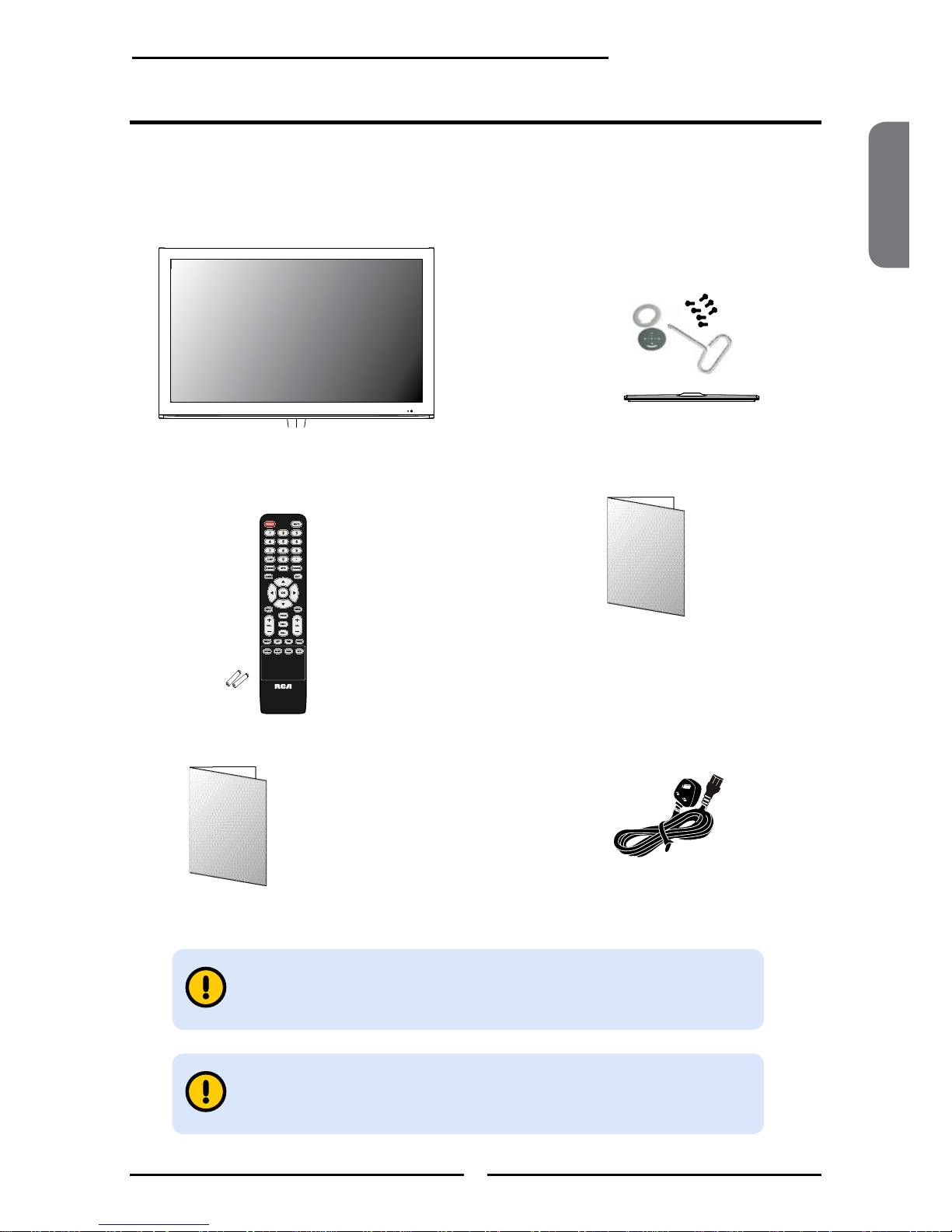
▪ Only use attachments/accessories specified by the manufacturer.
▪ Use only with the cart, stand, tripod, bracket, or table specified by the manufacture,
or sold with the apparatus. When a cart is used, use caution when moving the
cart/apparatus combination to avoid injury from tip-over.
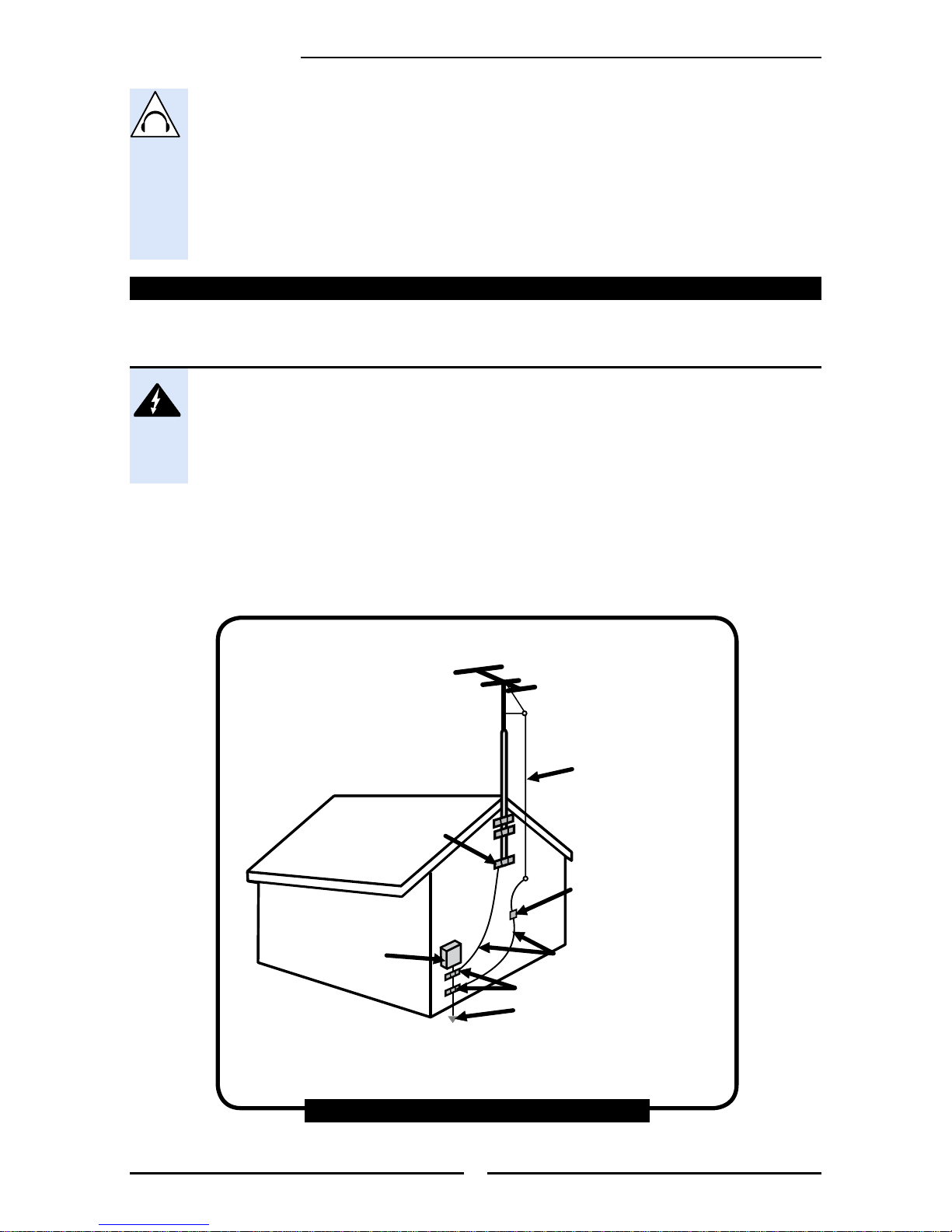
▪ Unplug this apparatus during lihgtning storms or when unused for long periods of time.
▪ Refer all servicing to qualified sevice personnel. Servicing is required when the apparatus has
been damaged in any way, such as power-supply cord or pllug is damaged, liquid has been
spilled or objects have fallen into the apparatus, the apparatus has been exposed to rain or
moisture, does not operate normally, or has been dropped.
▪ Opening and removing the covers may expose you to dangerous voltage or other hazards
and may void your warranty. Refer service to qualied personnel.
▪ The apparatus shall not be exposed to dripping or splashing and that no objects filled with
liquids,such as vases, shall be placed on the apparatus.
▪ The AC plug is used as disconnect device, the disconnect device shall remain readily
operable.
▪ Do not use this apparatus in the box or in the cabinet, it should be placed on a ventilation
area.
▪ The apparatus have not been considered wall mounting product. In order to avoid hazardous,
do not assemble the apparatus on wall.
▪ Warning: To reduce the risk of fire or electric shock, do not expose this apparatus to rain or
moisture.
▪ Refer all servicing to qualified service personnel. Servicing is required when the apparatus
has been admaged in any way, such as power-supply cord or plug is damaged, liquid has
been spilled or objects have fallen into the apparatus, the apparatus has been exposed to
rain or moisture, does not operate normally, or has been dropped.
▪ Always remove the power cord from the outlet before cleaning the equipment.
▪ Never use liquid or aerosol cleaners on the equipment.
Clean only with a soft dry cloth.
▪ Only use attachments/accessories specified by the manufacturer.
▪ Where the mains plug or an appliance coupler is used as the disconnected device, the
disconnect device shall remain readily operable.