RCA SCENIUM L26WD14 User manual

rca.com/television
Find Inside:
•Connections ...........page 6
• Remote...................page 19
• Features .................page 27
•Menus ....................page 36
•FAQs.......................page 45
•Troubleshooting .....page 46
LCD User’s Guide
1668591B.indb 11668591B.indb 1 6/5/06 3:27:28 PM6/5/06 3:27:28 PM

CAUTION
RISK OF ELECTRIC SHOCK
DO NOT OPEN
Caution: To reduce the risk of electric shock, do not remove cover (or
back). No user serviceable parts inside. Refer servicing to qualified service
personnel.
This symbol indicates important
instructions accompanying the product.
Product Registration
Please fill out the product registration card (packed separately) and return it immediately. For US customers: Your RCA
Consumer Electronics product may also be registered at www.rca.com/television. Registering this product allows us to
contact you if needed.
Product Information
Keep your sales receipt to obtain warranty parts and service and for proof of purchase. Attach it here and record the
serial and model numbers in case you need them. These numbers are located on the product.
Model No. _____________________ Serial No.____________________ Purchase Date __________________
Dealer/Address/Phone _________________________________________________________________________
Important Information
WARNING
To reduce the risk of fire or electric shock, do not
expose this product to rain or moisture. The apparatus
shall not be exposed to dripping or splashing. No ob-
jects filled with liquids, such as vases, shall be placed
on the apparatus.
Refer to the identification/rating label located on the back panel of your product for its proper operating voltage.
FCC Regulations state that unauthorized changes or modifications to this equipment may void the user’s authority to
operate it.
Cable TV Installer: This reminder is provided to call your attention to Article 820-40 of the National Electrical Code
(Section 54 of the Canadian Electrical Code, Part 1) which provides guidelines for proper grounding and, in particular,
specifies that the cable ground shall be connected to the grounding system of the building as close to the point of cable
entry as practical.
Important: This television is a table model and is designed to sit on a firm, flat, surface. Don't place the TV on soft
carpeting or similar surface because the ventilation slots on the bottom of the unit will be blocked resulting in reduced
lifetime from overheating. To assure adequate ventilation for this product, maintain a spacing of 4 inches from the top
and sides of the TV receiver and 2 inches from the rear of the TV receiver and other surfaces.
Also, make sure the stand or base you use is of adequate size and strength to prevent the TV from being accidentally
tipped over, pushed off, or pulled off. This could cause personal injury and/or damage the TV. Refer to the Important
Safety Instructions on the next page.
WARNING
The TV is unstable if it is not properly attached to the
base or mounted to the wall. Please follow the base
or wall mounting instructions provided in the User’s
Guide to ensure your safety.
This symbol indicates that this product contains mercury. Special disposal of this product for environmental
reasons may be required under the laws applicable to your jurisdiction. For disposal or recycling
information, please contact your local authorities or the Electronic Industries Alliance: www.eiae.org.
This symbol indicates "dangerous
voltage" inside the product that
presents a risk of electric shock or
personal injury.
1668591B.indb 21668591B.indb 2 6/5/06 3:27:59 PM6/5/06 3:27:59 PM

Important Information
Important Information i
Important Safety Instructions
1. Read these instructions.
2. Keep these instructions.
3. Heed all warnings.
4. Follow all instructions.
5. Do not use this apparatus near water.
6. Clean only with dry cloth.
7. Do not block any ventilation openings. Install in accordance with the manufacturer’s instructions.
8. Do not install near any heat sources such as radiators, heat registers, stoves, or other apparatus (including
amplifiers) that produce heat.
9. Do not defeat the safety purpose of the polarized or grounding-type plug. A polarized plug has two blades with
one wider than the other. A grounding type plug has two blades and a third grounding prong. The wide blade or
the third prong is provided for your safety. If the provided plug does not fit into your outlet, consult an electrician
for replacement of the obsolete outlet.
10. Protect the power cord from being walked on or pinched particularly at plugs, convenience receptacles, and the
point where they exit from the apparatus.
11. Only use attachments/accessories specified by the manufacturer.
12. Use only with the cart, stand, tripod, bracket, or table specified by the manufacturer, or sold with the
apparatus. When a cart is used, use caution when moving the cart/apparatus combination to avoid
injury from tip-over.
13. Unplug this apparatus during lightning storms or when unused for long periods of time.
14. Refer all servicing to qualified service personnel.
Servicing is required when the apparatus has been damaged in any way, such as power-supply cord or plug is
damaged, liquid has been spilled or objects have fallen into the apparatus, the apparatus has been exposed to rain
or moisture, does not operate normally, or has been dropped.
15. If an outside antenna or cable system is connected to the product, be sure the antenna or cable system is grounded
so as to provide some protection against voltage surges and built-up static charges. Section 810 of the National
Electrical Code, ANSI/NFPA No. 70-1984 (Section 54 of Canadian Electrical Code, Part 1) provides information
with respect to proper grounding of the mast and supporting structure, grounding of the lead-in wire to an
antenna-discharge unit, size of grounding conductors, location of antenna-discharge unit, connection to grounding
electrodes, and requirements for the grounding electrode. See following example.
ANTENNA
LEAD IN
WIRE
GROUND CLAMP
GROUNDING CONDUCTORS
(NEC SECTION 810-21)
GROUND CLAMPS
POWER SERVICE GROUNDING
ELECTRODE SYSTEM
(NEC ART 250, PART H)
ELECTRIC SERVICE
EQUIPMENT
ANTENNA
DISCHARGE UNIT
(NEC SECTION 810-20)
1668591B.indb 31668591B.indb 3 6/5/06 3:28:00 PM6/5/06 3:28:00 PM

4
Table of Contents
Important Safety Instructions....................................... i
Chapter 1: Connections and Setup
Things to Consider Before You Connect ..................... 5
Protect Against Power Surges................................ 5
Protect Devices from Overheating ........................ 5
Position Cables Properly to Avoid Audio
Interference .......................................................... 5
Use Indirect Light.................................................... 5
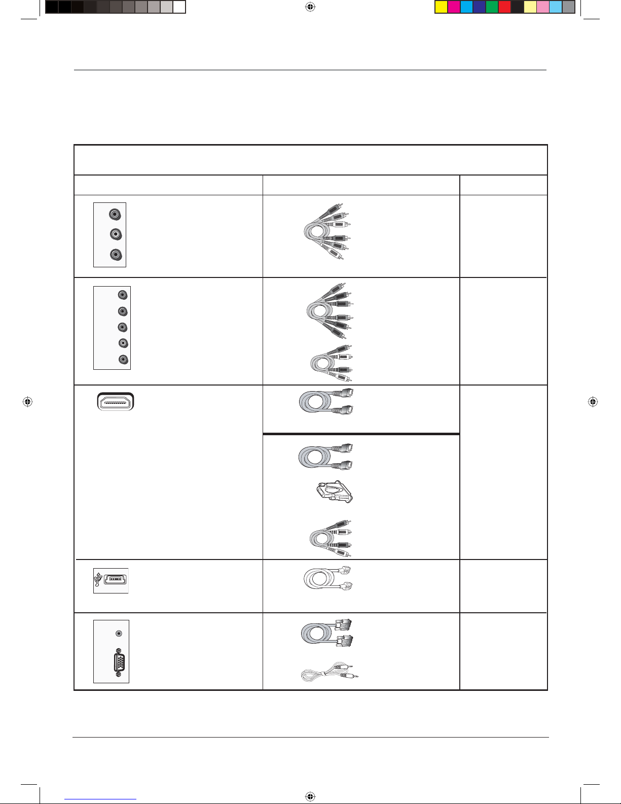
Check Supplied Parts .............................................. 5
Get the Picture .............................................................. 6
Getting Channels .................................................... 6
Choose Your Connection ............................................. 7
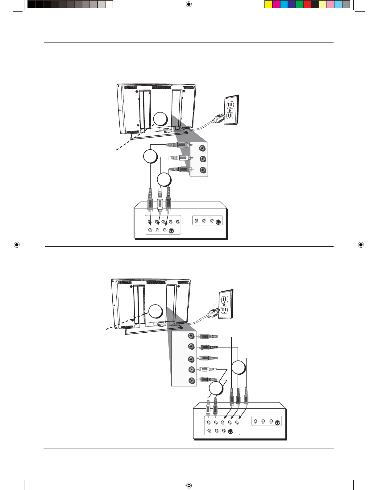
Video (Basic) Connection ....................................... 8
Component Video (Advanced) Connection .......... 8
HDMI/DVI Connection .......................................... 10
USB Connection .................................................... 12
VGA Connection ................................................... 13
Plug in the TV.............................................................. 14
Put Batteries in the Remote ....................................... 14
Turn on the TV............................................................. 14
How to Use the Remote Control to Complete the
Initial Setup ............................................................... 14
Complete the Initial Setup ......................................... 15
Set the Menu Language ...................................... 15
Complete Channel Setup ..................................... 15
What To Expect ........................................................... 16
Watching TV...............................................................16
Changing Channels............................................... 16
Explanation of Jacks (in alphabetical order)............. 17
Buttons and Other Jacks On Your TV ........................ 18
Side Input Jacks..................................................... 18
Front Panel Buttons.............................................. 18
Chapter 2: Using the Remote Control
The Buttons on the Remote Control.......................... 19
Using the INPUT Button ....................................... 20
Programming the Remote to Operate Other
Devices....................................................................... 20
Find Out If You Need to Program the Remote ... 20
Programming the Remote ................................... 21
How to Use the Remote After You’ve
Programmed It .......................................................... 22
Modes of Operation ............................................. 22
Volume Punchthrough Feature .................................. 22
Deleting ALL Volume Punchthrough
Commands .......................................................... 23
Remote Code List ........................................................ 24
Chapter 3: Using the TV's Features
Channel Banner........................................................... 27
Autotuning.................................................................. 27
Parental Controls and V-Chip ..................................... 29
How V-Chip Works for USA and Canada............. 29
Lock/Unlock Parental Controls............................. 29
US V-Chip TV Ratings............................................ 30
Blocking Canadian V-Chip Ratings ...................... 31
V-Chip Movie Rating Limit ................................... 32
Block Channels...................................................... 32
Front Panel Block.................................................. 32
Blocking Unrated/Exempt Programs ................... 33
Future Rating Region ........................................... 33
Additional Features .................................................... 33
Screen Formats...................................................... 33
PIP (Picture-in-Picture) Operation........................ 34
Chapter 4: Using the TV's Menu System
Using the Menu System ............................................. 36
Channel List Menu ...................................................... 36
Sound Menu ................................................................ 36
Picture Menu ............................................................... 38
PIP Menu...................................................................... 40
Setup Menu ................................................................. 40
Parental Control Menu ............................................... 42
Time Menu................................................................... 43
USB Menu .................................................................... 43
Chapter 5: Other Information
Frequently Asked Questions (FAQs).......................... 45
Troubleshooting.......................................................... 46
Mounting Your TV to the Wall................................... 49
V-Chip Rating Explanations........................................ 50
US V-Chip Rating System ...................................... 50
Canadian English V-Chip Rating System.............. 50
Canadian French V-Chip Rating System .............. 51
Limited Warranty ........................................................ 52
Care and Cleaning....................................................... 53
1668591B.indb 41668591B.indb 4 6/5/06 3:28:01 PM6/5/06 3:28:01 PM

Chapter 1 5
Graphics contained within this publication are for representation only.
Chapter 1: Connections and Setup
Things to Consider Before You Connect
Protect Against Power Surges
• Connect all devices before you plug any of their power cords into the wall outlet or power
strip. NEVER plug your TV into an outlet that is controlled by a wall switch.
• Turn off the TV and/or device(s) before you connect or disconnect any cables.
• Make sure all antennas and cables are properly grounded. Refer to the Important Safety
Instructions at the beginning of the User's Guide.
Protect Devices from Overheating
• Don’t block ventilation holes on any of the devices. Arrange the devices so that air can
circulate freely.
• Don’t stack devices.
• If you place devices in a stand, make sure you allow adequate ventilation.
• If you connect an audio receiver or amplifier, place it on the top shelf so the heated air
from it won’t flow around other devices.
Position Cables Properly to Avoid Audio Interference
• Insert each cable firmly into the designated jack.
• If you place devices above the TV, route all cables down the side of the back of the TV
instead of straight down the middle.
• If your antenna uses 300-ohm twin lead cables, do not coil the cables. Also, keep the twin
lead cables away from audio/video cables.
Use Indirect Light
Don’t place the TV where sunlight or room lighting will be directed toward the screen. Use soft
or indirect lighting.
Check Supplied Parts
Check that the following parts were packed with your product.
Remote control
Part # R301C1
2 AA batteries Power cord
INPUT SUB CH
MENU
CLEAR
ZOOM-
CH CTRL
GUIDE
MUTE
GO BACK
VOL CH
ON•OFF
TV SAT•AUX DVD PIP
PRESETS
INFO
ZOOM+
+
Note: If you need to replace your remote, call 1-800-338-0376. A shipping and handling
fee, and the appropriate sales tax, will be charged upon ordering. Have your Visa,
MasterCard, or Discover Card ready.
1668591B.indb 51668591B.indb 5 6/5/06 3:28:01 PM6/5/06 3:28:01 PM

Connections and Setup
6 Chapter 1
Get the Picture
The first part of connecting your TV is to get the picture, also known
as the signal. The back panel of your TV allows you to receive analog
and/or digital channels by using the ANT/CABLE INPUT. See the
graphic to the left for the location of the jack.
ANT/CABLE INPUT
Coaxial cable
Outdoor or Indoor
antenna
or
Getting Channels
What You Need
• Antenna ("rabbit ears") or outdoor antenna with coaxial cable
OR
• Coaxial cable with cable service
A. Do you have an indoor or outdoor antenna? If not, go to step B. If
so, plug the antenna or coaxial cable from the wall outlet into the
ANT/CABLE Input to receive free off-air local digital and analog
channels.
B. Do you have cable? If so, plug the coaxial cable from the wall
outlet into the ANT/CABLE Input to receive your cable channels.
C. Do you have a set-top box? If so, you need to call your cable
company or satellite service provider. They may use special cables
to allow you to view digital channels.
What You Need To Know
• Visit www.antennaweb.org to get help deciding what type of
antenna to use to receive the local digital channels available to
you. By entering where you live, this mapping program tells you
what local analog and digital stations are available using a certain
antenna.
• When you are ready to watch channels, the channel banner
displays the type of channel you're viewing. Look for a Dat the
bottom of the screen for digital channels; look for an Afor analog
channels. Go to page 16 for more information.
1668591B.indb 61668591B.indb 6 6/5/06 3:28:02 PM6/5/06 3:28:02 PM

Connections and Setup
Chapter 1 7
Jacks Used Cables Needed Go to...
Audio/Video page 8-9
page 10-11
HDMI™
OR
Video1
Audio1 R and L
HDMI/DVI
HDMI, the HDMI logo, and High-Definition Multimedia Interface are trademarks or registered trademarks of HDMI Licensing LLC.
HDMI™
HDMI/DVI adapter
Choose Your Connection
For additional assistance while using your RCA product, please visit www.rca.com/customersupport.
R
AUDIO1
VIDEO1
L
VGA
AUDIO
VGA
VIDEO
VGA
Audio
page 13
Audio
VGA
+
+
Audio
There are several ways to connect your TV. Please use the following chart to determine which connection is best
for you. Proceed to the appropriate page and connect your TV.
R
AUDIO
COMPONENT
INPUT
(CMP1)
Y
Pb/Cb
Pr/Cr
L
Y Pb/Cb Pr/Cr
Audio R and L
Audio
Component Video page 8-9
USB page 12
USB
1668591B.indb 71668591B.indb 7 6/5/06 3:28:02 PM6/5/06 3:28:02 PM

Connections and Setup
8 Chapter 1
COMPONENT VIDEO
YPb Pr
VIDEO
INPUT LR
AUDIO
VIDEO
OUTPUT
S-VIDEO
S-VIDEO
LR
AUDIO
LR
AUDIO
R
AUDIO1
VIDEO1
L
Video (Basic) Connection
This is an example of a connection using the Video jack. Go to the top of page 9 for specific
instructions.
1
Don't forget: If necessary,
connect antenna or cable to
get a picture. Go to page 6 for
instructions.
2
3
COMPONENT VIDEO
Y Pb Pr
VIDEO
INPUT L R
AUDIO
VIDEO
OUTPUT
S-VIDEO
S-VIDEO
L R
AUDIO
L R
AUDIO
R
AUDIO
COMPONENT
INPUT
(CMP1)
Y
Pb/Cb
L
Pr/Cr
Component Video (Advanced) Connection
This is an example of a connection using the Component Video jacks. Go to the middle of
page 9 for specific instructions.
1
Don't forget: If necessary,
connect antenna or cable to
get a picture. Go to page 6 for
instructions.
2
3
1668591B.indb 81668591B.indb 8 6/5/06 3:28:04 PM6/5/06 3:28:04 PM

Connections and Setup
Chapter 1 9
• If you're done
connecting devices to
your TV, go to page 14
to complete the Initial
Setup.
• To continue
connecting devices, go
to the next page.
Connecting the Device with Component Video (Advanced)
This connection allows you to connect a device that has Y Pb Pr or Y Cb Cr jacks, for
example, a DVD player.
Using the example of a DVD player:
1. If necessary, connect your cable and/or off-air antenna as described on page 6.
2. Connect your Y Pb Pr component video cables.
Connect three video cables or special Y Pb Pr cables to the COMPONENT INPUT
(CMP1) Y Pb/Cb Pr/Cr jacks on the back of the TV and to the Y Pb Pr or Y Cb Cr
outputs on the DVD player.
3. Connect your red and white audio cables.
Connect the audio (red and white) cables to the CMP1 AUDIO R and L jacks on the
back of the TV and to the Audio Output jacks on the DVD player.
INPUT SUB CH
MENU
CLEAR
ZOOM-
CH CTRL
GUIDE
MUTE
GO BACK
VOL CH
ON•OFF
TV SAT•AUX DVD PIP
PRESETS
INFO
ZOOM+
+
INPUT
button
ON•OFF button
Use these buttons
to view the picture
of the device you’ve
connected to the TV.
Connecting the Device with Video (Basic)
This connection allows you to connect a device that has a Video Out jack, for example, a
DVD player.
Note: If the device you're connecting also has Component Video jacks and you have
component video cables, we recommend you use the Component Video (Advanced)
Connection instead. See instructions below.
Using the example of a DVD player:
1. If necessary, connect your cable and/or off-air antenna as described on page 6.
2. Connect your yellow video cable.
Connect a video cable to the VIDEO1 Input jack on the back of the TV and to the Video
Output jack on the DVD player.
3. Connect your red and white audio cables.
Connect the audio (red and white) cables to the AUDIO1 R and L/MONO jacks on the
back of the TV and to the Audio Output jacks on the DVD player.
Red
Yellow
Composite cables are color
coded- Yellow= video;
Red= right audio; white=
left audio
White
Component Video cables
(Y Pb Pr) are color coded-
Green, Blue and Red
White
Red
Audio cables are color
coded- Red= right audio;
white= left audio
Green
Blue
Red
Viewing the Picture from the Connected Device
1. Plug in the TV (see page 14 for details) and the device, if they aren't already
plugged in.
2. Turn on the TV and the device you want to view, for example a DVD player.
3. Repeatedly press the INPUT button on the remote control until you see VID1 (if
connected to the VIDEO1 jack) or CMP1 (if connected to the CMP1 jacks) displayed
at the bottom of the TV's screen. To go back to viewing TV channels, use the number
buttons to enter the channel or press CH+/- to go to the channel list from the input list.
Note: If the picture from the DVD player appears black and white and your device
is connected to the VIDEO Input, you might be tuned to the wrong input. Make sure
you press INPUT until you see VID1 displayed at the bottom of the TV's screen.
1668591B.indb 91668591B.indb 9 6/5/06 3:28:06 PM6/5/06 3:28:06 PM

Connections and Setup
10 Chapter 1
OR
Device with DVI
L
R
Device with HDMI
Audio Out
DVI Out
Pb
Y
Video Out
Pr
HDMI Out
L
R
Audio Out
R
DVI/
AUDIO
HDMI1
/DVI
L
B
HDMI/DVI Connection
This is an example of a connection using the HDMI/DVI jack.
A
*Don't forget: If necessary, connect
antenna or cable to get a picture. Go
to page 6 for instructions.
C
*
1668591B.indb 101668591B.indb 10 6/5/06 3:28:07 PM6/5/06 3:28:07 PM

Connections and Setup
Chapter 1 11
HDMI cable
HDMI/DVI adapter
White
Red
Audio cables are color
coded- Red= right audio;
White= left audio
HDMI cable
Connecting the Device
High-Definition Multimedia Interface (HDMI) technology is an uncompressed digital connection
that carries both video and audio data by way of an integrated mini-plug cable. Since HDMI
technology is based on Digital Visual Interface (DVI), the jack on the back of your TV is also
compatible with devices that have a DVI output jack.
Viewing the Picture from the Connected Device
The device in this connection is connected to the HDMI1/DVI jack. To view this device:
1. Plug in the TV (see page 14 for details) and the device, if they aren't already plugged
in.
2. Turn on the TV and the device you want to view, for example a set-top box.
3. Repeatedly press the INPUT button on the remote control until you see HDMI1
displayed at the bottom of the TV's screen. To go back to viewing TV channels, use
the number buttons to enter the channel or press CH+ or CH- buttons.
Using the example of a set-top box:
• If your set-top box has an HDMI jack, connect an HDMI cable.
Connect an HDMI cable to the HDMI1/DVI Input jack (or the HDMI2 jack if it is more
convenient) on the back of the TV and to the HDMI Out jack on the back of the
device.
–OR–
• If your set-top box has a DVI jack, connect an HDMI cable and an
HDMI/DVI adapter.
A. Connect an HDMI cable to the HDMI1/DVI Input jack on the back of the TV.
B. Attach an HDMI/DVI adapter to the end of the HDMI cable, then connect the
adapter to the DVI Out jack on the set-top box.
C. Since you’re using an HDMI/DVI adapter, you need to connect Audio left and right
cables to the DVI AUDIO R and L jacks on the back of the TV and to the R and L
jacks on the back of the device.
INPUT SUB CH
MENU
CLEAR
ZOOM-
CH CTRL
GUIDE
MUTE
GO BACK
VOL CH
ON•OFF
TV SAT•AUX DVD PIP
PRESETS
INFO
ZOOM+
+
INPUT
button
ON•OFF button
Use these buttons to
view the picture of the
device you’ve connect-
ed to the TV.
• If you're done connecting
devices to your TV, go to
page 14 to complete the
Initial Setup.
• If you experience HDMI
problems, go to the HDMI
Troubleshooting section on
page 47.
1668591B.indb 111668591B.indb 11 6/5/06 3:28:08 PM6/5/06 3:28:08 PM

Connections and Setup
12 Chapter 1
USB Connection
This is an example of a connection using the USB jack.
Connecting the Device
This connection allows you to connect to a compatible mass storage device with USB, such as
a digital camera, JumpDrive (FlashDrive), or mp3 player.
• Connect one end of the USB cable to the USB device and the other end to the USB jack on
the TV.
ON/OFF
PLAY
INPUT SUB CH
MENU
CLEAR
ZOOM-
CH CTRL
GUIDE
MUTE
GO BACK
VOL CH
ON•OFF
TV SAT•AUX DVD PIP
PRESETS
INFO
ZOOM+
+
INPUT
button
ON•OFF button
Use these buttons
to view the picture
of the device you’ve
connected to the TV.
Viewing the Connected Device
1. Plug in the TV and the USB device, if they aren't already plugged in.
2. Turn on the TV and the device.
3. To access and adjust the options of the USB device, press MENU then choose USB from the
Main menu. Go to page 43 for more information.
Note: When using a USB connection, you can play a picture slideshow from a folder not
a picture.
1668591B.indb 121668591B.indb 12 6/5/06 3:28:08 PM6/5/06 3:28:08 PM

Connections and Setup
Chapter 1 13
VGA Connection
This is an example of a connection using the VGA jacks.
VGA
AUDIO
VGA
VIDEO
Connecting the Device
This connection allows you to connect to a personal computer.
1. If necessary, connect your cable and/or off-air antenna as described on page 6.
2. Connect your monitor cable.
Connect one end of a 15-pin monitor cable to the VGA VIDEO jack on the TV and the
other end to the PC's video output jack. Note, if your PC's video output isn't 15-pin, you'll
need an adapter that can connect to a 15-pin monitor cable.
3. Connect your audio cable.
Connect a 3.5 mm stereo mini pin cable (sometimes referred to as 1/8" stereo mini pin) to
the VGA AUDIO jack on the back of the TV and the other end to the Audio Output jack on
the PC.
Notes: The maximum resolution is 1024 x 768. Be sure to set your PC to the correct
monitor output setting.
To hear sound from the TV while using the PC, press the PRESETS button. Highlight
PC Sound source and press the right arrow to choose TV tuner. Go to page 35 for more
information about how to use PIP with this connection.
Viewing the PC
1. Plug in the TV and the PC, if they aren't already plugged in.
2. Turn on the TV and the PC.
3. Repeatedly press the INPUT button on the remote control until you see VGA displayed at
the bottom of the TV's screen. To go back to viewing TV channels, use the number buttons
to enter the channel or press CH+ or CH- buttons.
1
Don't forget: If necessary,
connect antenna or cable to
get a picture. Go to page 6 for
instructions. 2
3
1668591B.indb 131668591B.indb 13 6/5/06 3:28:09 PM6/5/06 3:28:09 PM

Connections and Setup
14 Chapter 1
INPUT SUB CH
MENU
CLEAR
ZOOM-
CH CTRL
GUIDE
MUTE
GO BACK
VOL CH
ON•OFF
TV SAT•AUX DVD PIP
PRESETS
INFO
ZOOM+
+
Plug in the TV
Plug the end of the power cord into the back of the TV. Plug the other end into a grounded
wall outlet. Insert the plug completely into the outlet. Do not plug into an outlet controlled by
a light switch.
Put Batteries in the Remote
• Remove the battery compartment cover from the back of the remote by pushing the tab
and lifting off the cover.
• Insert two fresh batteries. Make sure the polarities (+ and -) are aligned correctly.
• Replace the cover.
Turn on the TV
Turn on your TV by pressing the Power button on the front of the TV or ON•OFF on the
remote control.
Tip
To access the setup menus manually, press MENU and
choose Setup.
Arrows
OK
button
How to Use the Remote Control to
Complete the Initial Setup
The technical term is “Navigation” – how you move through the on-
screen menus. The theory is the same throughout the menu screens:
highlight your choice and select it.
To highlight a menu item, press the arrow buttons on the remote to
highlight one of the items listed on the screen. Use the up or down
arrow button to move up or down. Use the right or left arrow button
to view other selections for a menu choice or to display a sub-menu.
More than one selection displays, for example, On...; a menu choice
with a sub-menu displays dots (...).
Note: Highlighted means that the menu item stands out from
other menu items on the list (appears darker, brighter, or a
different color).
1668591B.indb 141668591B.indb 14 6/5/06 3:28:10 PM6/5/06 3:28:10 PM

Connections and Setup
Chapter 1 15
Complete the Initial Setup
The menu system in your TV allows the TV’s features to work properly. The first time you turn
on your TV, the language screen appears.
Channel setup
Go back
Signal type Cable...
Auto Channel search ...
English
Français
Español
Set the Menu Language
The first part of the setup allows you to select your preferred language
for the menu system.
If English is your preferred language, press OK. To choose another
language, press the down arrow button until that language is
highlighted, and press OK.
Complete Channel Setup
Make sure you've connected the TV to cable and/or an off-air signal
before you start the next part of the setup.
Set the Signal Type
If you connected Cable to your ANT/CABLE jack, the option is chosen
for you and you can press the down arrow button to continue. To
choose Antenna, press the right arrow button and then press the down
arrow button to continue.
Channel setup
Go back
Signal type Cable...
Auto Channel search Running...
Progress
Analog Channels found 10
Digital Channels found 05
Ch. search in progress. Press CLEAR to cancel
Any channels already found will be stored.
If you have analog and digital channels,
the TV's search might take longer since it is
looking for both.
Complete the Channel Search
Even though the initial channel search can take several minutes, you
must complete it in order for your TV to display channels and pro-
gramming. Press OK to begin the channel search. The menu shows the
TV is running a channel search. When it's complete, the Channel setup
menu remains on-screen. To exit the menu system, press CLEAR.
Some channels might have been found during the channel search that
are unavailable to view and you might want to get rid of these so they
don't appear as you change channels. To do this press OK (the List
and Labels menu appears). Note that removing channels from your
channel list may be time consuming, so you might want to do it later.
Go to page 40 for details on editing your channel list.
1668591B.indb 151668591B.indb 15 6/5/06 3:28:10 PM6/5/06 3:28:10 PM

Connections and Setup
16 Chapter 1
What To Expect
Watching TV
• Remember: Look for an Aat the bottom of the screen to see if
you're watching an analog channel.
Analog video is sent in a 4/3 format, which your TV displays these
channels in a 16/9 format. Press the ZOOM+/- button to view the
different formats available. Go to page 33 for more explanation of
screen formats.
• Remember: Look for a Dat the bottom of the screen to see if
you're watching a digital channel.
Most digital video is sent in a 16/9 format which does fill your
screen, but sometimes is sent in 4/3 which does not fill your
screen. It depends on how the station or source device is
formatting the video. If there are bars on-screen, press the
ZOOM+/- button to try a different format that may eliminate
the bars. Go to page 33 for more explanation of screen formats.
Look for the Aat the bottom of the screen to
see if you're watching an analog channel.
Look for the Dat the bottom of the screen to
see if you're watching a digital channel.
A10 CBS
D10-1 CBS
Changing Channels
• Digital channels can have both primary channels (like the analog
channel number) and sub-channels. To tune to a digital channel
with a sub-channel, enter the primary channel number, then press
either the right arrow or the SUB CH button. Enter the sub-channel
number and press OK.
• Depending upon the type of signals you have connected to your
HDTV, you might notice that the channels change slower than
you’re used to. This is perfectly normal. Digital cable channels
sometimes take longer to tune.
1668591B.indb 161668591B.indb 16 6/5/06 3:28:10 PM6/5/06 3:28:10 PM

Connections and Setup
Chapter 1 17
Explanation of Jacks (in alphabetical order)
This section describes the jacks on the back panel of your TV. There are several ways to
connect devices.
ANT/CABLE Input Lets you connect a coaxial cable to receive the signal from your antenna,
cable, or cable box.
COMPONENT INPUTS Lets you connect a device that has component video jacks, such as a
DVD player.
• CMP1 Y Pb/Cb Pr/Cr (Component Video) Provides optimum picture quality because the
video is separated into three signals. Use three video-grade or component video cables for
the connection. When using CMP1 Y Pb/Cb Pr/Cr, make sure you connect left and right
audio cables to the CMP1 L and R AUDIO jacks.
• CMP1 L AUDIO Provides left audio connection when using the CMP1 video inputs. The left
audio connector is usually white.
• CMP1 R AUDIO Provides right audio connection when using the CMP1 video inputs. The
right audio connector is usually red.
• CMP2 Y Pb/Cb Pr/Cr (Component Video) Same as described for CMP1 Y Pb/Cb Pr/Cr and
CMP1 Audio above. Make sure you connect the left and right audio cables to the CMP2 L
and R AUDIO jacks.
HDMI1/DVI Input Lets you connect a device, such as a digital cable box, with an HDMI or a
DVI output.
• HDMI1/DVI INPUT (High-Definition Multimedia Interface/Digital Visual
Interface) Provides an uncompressed digital connection that carries both video and
audio data by way of an integrated mini-plug cable. Since HDMI technology is based on
Digital Visual Interface (DVI), the jack on the back of your TV is also compatible with DVI
devices.
• L AUDIO (used for DVI only) Provides left audio connection when using the DVI jack.
The left audio connector is usually white.
• R AUDIO (used for DVI only) Provides right audio connection when using the DVI jack.
The right audio connector is usually red.
Note: Remember to connect the left and right audio cables because the DVI cable carries
only the picture signal, not the sound.
HDMI2 Input Lets you connect a device, such as a digital cable box, with an HDMI output.
SPDIF OUT Use a digital coaxial cable to connect your TV to a compatible audio receiver.
VGA Connect your computer, or other device with a VGA output, to this jack using a 15 pin
D-sub cable. Go to page 34 for more information about how to use PIP with this connection.
VGA AUDIO (Stereo mini jack) Use to obtain sound when a PC is connected to the VGA jack.
Use a 3.5 mm stereo mini pin cable (sometimes referred to as 1/8” stereo mini pin) to connect
a PC to your TV.
VIDEO1 Input Lets you connect a device that has composite video jacks, such as a VCR or
DVD player.
• L AUDIO Provides left audio connection when using the VIDEO1 jack. The left audio
connector is usually white.
• R AUDIO Provides right audio connection when using the VIDEO1 jack. The right audio
connector is usually red.
1668591B.indb 171668591B.indb 17 6/5/06 3:28:11 PM6/5/06 3:28:11 PM

Connections and Setup
18 Chapter 1
VIDEO OUT Connect a VCR or DVD-recorder to record digital and analog programs from the
Digital or Analog Input (excluding copy-protected programs and component video formats)
while the TV is turned on. You must leave the TV on the same channel you are recording.
• L (AUDIO) Provides left audio connection. The left audio connector is usually white.
• R (AUDIO) Provides right audio connection. The right audio connector is usually red.
Buttons and Other Jacks On Your TV
Side Input Jacks
USB Allows you to connect a compatible mass storage device with a USB jack. Go to page 12
for more information.
(Headphones) Allows you to connect headphones to listen to the sound coming from the
TV. To adjust volume control of the headphones, go to the Headphone settings option in the
Sound menu.
S-VIDEO Input Allows you to connect an S-Video cable from another device. Make sure you
also connect audio cables from the device to the TV. To access a device connected to the
S-VIDEO jack, press the INPUT button on your remote until VID2 appears at the bottom of the
screen.
VIDEO2 Input Receives video from another device such as a camcorder, video game console,
VCR, or DVD player. To access a device connected to the VIDEO jack, press the INPUT button
on your remote until VID2 appears at the bottom of the screen.
Note: Do not connect an S-Video and a regular video cable to the side jacks at the same
time.
AUDIO L/MONO and R Receives audio from another device such as a camcorder, video game
console, VCR, or DVD player. Use when connecting to the VIDEO or S-VIDEO Input.
Front Panel Buttons
If you cannot locate your remote, you can use the front panel buttons of your TV to operate
many of the TV’s features.
MENU Brings up the TV Main menu.
VOL < Decreases the volume. In the TV menu system, acts like the left arrow button on the
remote control and adjusts menu controls.
VOL > Increases the volume. In the TV menu system, acts like the right arrow button on the
remote control and adjusts menu controls.
CH Scans down through the channel list. In the TV menu system, acts like the down arrow
button on the remote control and adjusts menu controls.
CH Scans up through the channel list. In the TV menu system, acts like the up arrow button
on the remote control and adjusts menu controls.
(Power indicator) Turns the TV on and off.
>
>
1668591B.indb 181668591B.indb 18 6/5/06 3:28:11 PM6/5/06 3:28:11 PM

Chapter 2 19
Graphics contained within this publication are for representation only.
Chapter 2: Using the Remote Control
The Buttons on the Remote Control
Alphanumeric Buttons Enter channel numbers; time settings; and
options with letters, such as the Message option, using these buttons.
To enter a channel, press the number buttons and press OK (or just let
the entry timeout).
To enter a digital channel with a sub-channel, enter the main channel,
then press the right arrow to enter the sub-channel and press OK.
Arrows Used to highlight different items in the TV menu and to
adjust the menu controls. When viewing a channel, press the left
or right arrow to change the screen format: 4/3, 16/9 zoom,
Cinerama, and 16/9. Go to page 33 for more information on screen
formats.
CH + or CH - Scans up or down through the current channel list.
Press once to change the channel up or down; press and hold to
continue changing channels.
CH CTRL (Channel control) Toggles between the main TV picture
and the PIP window. Use CH+/-, INPUT, SAT•AUX, DVD, or the
number buttons to change channels in PIP.
CLEAR Removes any menu or display from the screen and returns
you to normal viewing.
GO BACK Returns you to the previous channel.
GUIDE Displays an electronic program guide (when available).
INFO If no menus are on-screen, displays the channel banner; press
again to clear the screen.
INPUT Accesses the available video input channels (VID1, VID2,
CMP1, CMP2, VGA, HDMI1 and HDMI2). To resume TV viewing, press
the number buttons to enter the channel or press CH+ or CH- buttons.
MENU Brings up the Main menu.
MUTE Reduces the TV’s volume to its minimum level. Press again
to restore the volume. To program this button to work with an audio
system, follow the instructions for Volume Punchthrough Feature on
page 22.
OK When in the menu system, selects highlighted items.
ON•OFF When in TV mode, turns the TV on or off. If in another
mode (SAT•AUX or DVD) and programmed, will turn the device on or
off.
PIP Makes the PIP or POP window appear and disappear. Go to
page 34 for more information on PIP.
PRESETS Displays Picture and Sound preset; CC Settings; Current
Audio Track, PC Sound source; and CH+/CH- buttons.
REVERSE, PLAY, FORWARD, RECORD, STOP, PAUSE (buttons at
bottom of the remote) If programmed, provides transport control
for some remote-controllable VCRs or DVD players.
Tip
To turn off most RCA, GE, and Proscan components
that are connected to the TV, press ON•OFF twice
within two seconds.
This feature only works with most RCA, GE, and
Proscan products.
Note: If you need to replace your
remote, call 1-800-338-0376. A
shipping and handling fee, and the
appropriate sales tax, will be charged
upon ordering. Have your Visa,
MasterCard, or Discover Card ready.
Remote control part number R301C1
INPUT SUB CH
MENU
CLEAR
ZOOM-
CH CTRL
GUIDE
MUTE
GO BACK
VOL CH
ON•OFF
TV SAT•AUX DVD PIP
PRESETS
INFO
ZOOM+
+
1668591B.indb 191668591B.indb 19 6/5/06 3:28:12 PM6/5/06 3:28:12 PM

Using the Remote Control
20 Chapter 2
SAT•AUX Places the remote in SAT•AUX mode. If Auto Tuning is enabled, turns on the TV
and tunes it to the satellite or cable box Video Input Channel. This button lights when you
press a valid button in SAT•AUX mode (see Modes of Operation on page 22 for more details).
SUB CH When entering a digital channel that has a subchannel, press this button to access
the subchannel entry field. Once the channel is entered, press the OK button to tune to the
channel.
TV Turns on the TV and puts the remote in TV mode. Also displays current status.
VOL – or VOL + Decreases or increases the TV’s volume. To program this button to work
with an audio system, follow the instructions for Volume Punchthrough Feature on page 22.
ZOOM– or ZOOM + When viewing a channel, press to change the screen format: 4/3, 16/9
zoom, Cinerama, and 16/9. Go to page 33 for more information on screen formats.
Using the INPUT Button
Use the INPUT button to scroll through the available video input channels and view devices
you have connected to the TV.
1. Make sure the device you want to view is turned ON.
2. Press INPUT to tune to an available video input source and view the device.
3. To return to the previous channel, press INPUT until you return to the channel.
Programming the Remote to
Operate Other Devices
The universal remote can be programmed to operate many brands of
remote-controllable VCRs, audio devices, DVD players, cable boxes,
satellite receivers and other devices. In addition to being programmed
to operate your television, it’s already programmed to operate some
RCA devices.
Notes: The TV button can’t be programmed on this remote to
control any device; it controls only this TV.
The remote may not be compatible with all models of all brands
of devices. It also may not operate all functions of your device.
Find Out If You Need to Program the Remote
To determine whether the universal remote needs to be programmed
to operate one of the devices connected to your TV, such as a VCR, do
the following:
1. Turn on the device (in this example, a VCR).
2. Point the remote at the device.
3. Press the corresponding device button (in this example, VCR).
4. Press ON•OFF to see if the VCR responds. If the VCR doesn’t
respond, you need to program the remote to operate it.
INPUT SUB CH
MENU
CLEAR
ZOOM-
CH CTRL
GUIDE
MUTE
GO BACK
VOL CH
ON•OFF
TV SAT•AUX DVD PIP
PRESETS
INFO
ZOOM+
+
The darkened buttons are the device buttons
that can be programmed.
1668591B.indb 201668591B.indb 20 6/5/06 3:28:12 PM6/5/06 3:28:12 PM
Other manuals for SCENIUM L26WD14
1
This manual suits for next models
2
Table of contents
Other RCA LCD TV manuals