READ INSTRUCTIONS CAREFULLY BEFORE USING
THIS PRODUCT. SAVE INSTRUCTIONS FOR
LATER REFERENCE.
PRODUCT IS NOT SUITABLE FOR PHASE DIMMING
Products must be installed by a suitably qualified
professional only. Installations must conform to national
installation codes and accident prevention regulations.
If using a track adaptor, ensure it is compatible with the
track system installed. Failure to do so may result in
danger of electric shock and damage to the product.
Ensure electrical rating shown on product label
conforms to mains voltage supply.
Do not modify the product in any way. RCL accepts
no responsibility for damage caused by modifying
this product.
Product is rated IP20 unless otherwise stated. Install
indoors only and away from damp or wet environments.
This symbol indicates the minimum distance to a
lighted object and must be observed.
Caution, product will become hot in use. Allow to cool
before touching.
Dispose of this product in accordance with WEEE or
other national regulations.
Products marked with this symbol are compliant with
Class 2 regulations.
If you have any diculty installing this product
please contact:
Remote Controlled Lighting Ltd (UK)
42 Riverside Road, London SW17 0BA
+44 (0) 20 8404 2400
Remote Controlled Lighting Ltd (Asia)
Unit 13, 8/F, Lai Sun Yuen Long Centre
21-35 Wang Yip Street East,
Yuen Long, Hong Kong
+852 2310 9733
Installation Instructions
Remote Controlled Spotlight Type DR2
Important Safety Information
DOC-033-C
Copyright © 2016 Remote Controlled Lighting Ltd. All Rights Reserved.
BEFORE YOU START
Read these instructions carefully. For the latest
instructions on all our products see
www.rclighting.com/downloads
These instructions cover the following
installation methods:
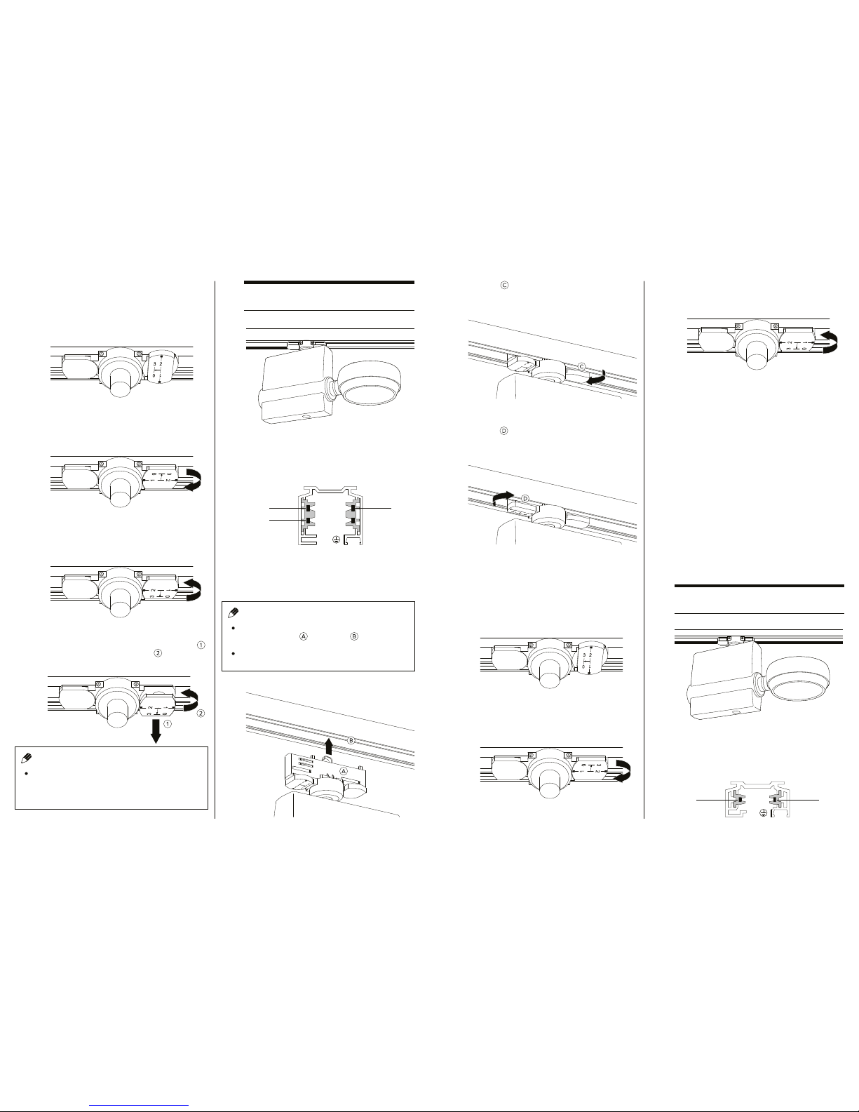
Monopoint Installation
3-Circuit Installation
2-Circuit Installation
1-Circuit Installation
Hook Clamp Installation
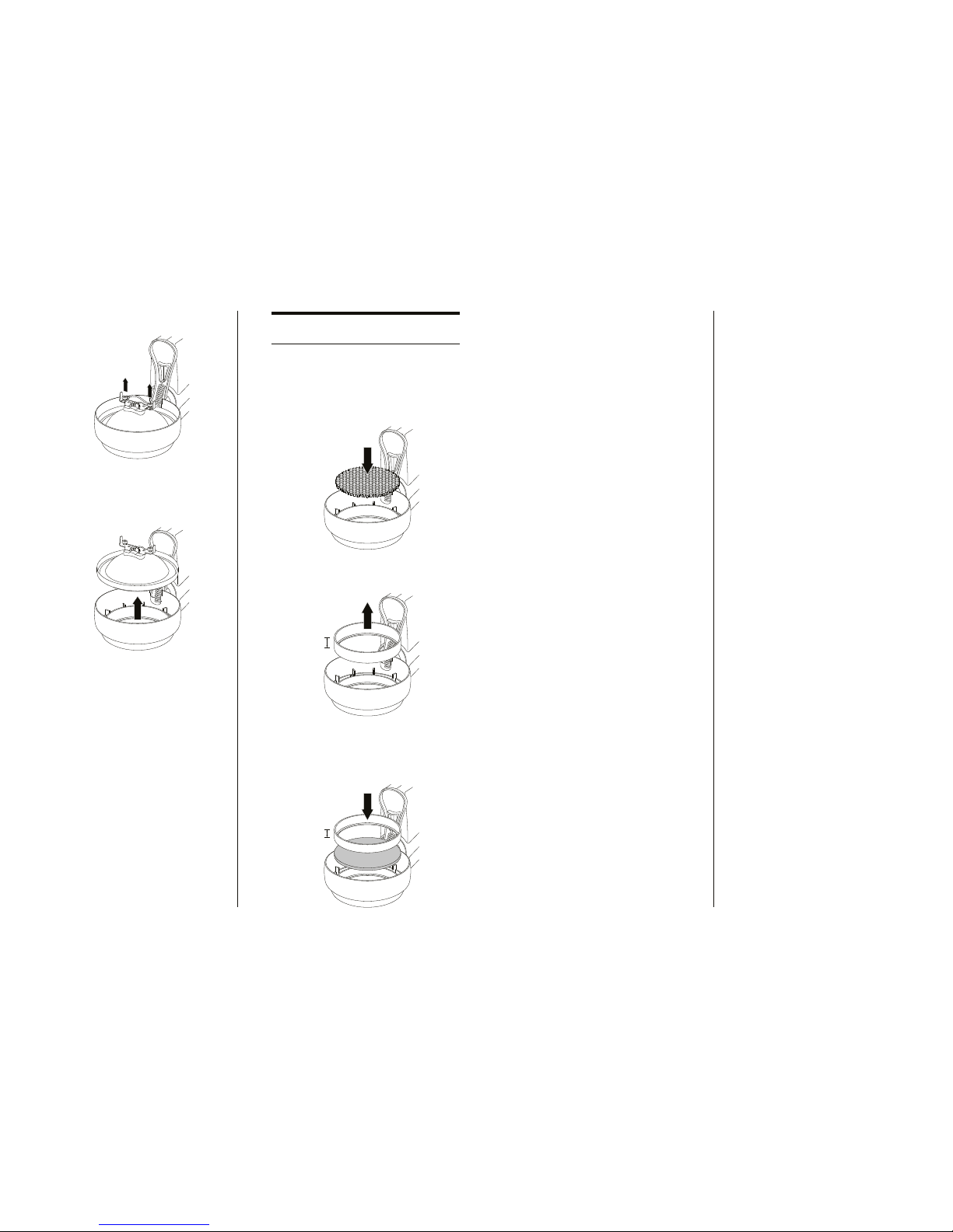
Lamp Change - QR111
Accessory Change - QR111
A
B
C
D
E
F
G
1
4
5
6
7
The monopoint fixture requires a minimum clearance
distance of 200mm above and around the mounting
point and a maximum ceiling material thickness of
between 3mm and 35mm.
2Mark up the ceiling and cut a circular hole 115mm in
diameter.
3For multiple installations, ensure a minimum distance
of 400mm between mounting points.
AMonopoint Installation
PAGE 1
Insert the mounting ring into the hole so that it sits
flush with the ceiling.
Holding the mounting ring in place, insert a fixing clip
into a slot on the mounting ring.
Slide the fixing clip down the slot until it hits the
ceiling material.
Insert fixing studs into mounting ring holes and, using
a 2.5mm hex screwdriver, secure the clip in place.
Repeat this process for each fixing clip.
200mm MIN.
200mm MIN.
Ø3 - 35mm
115mm
400mm MIN.