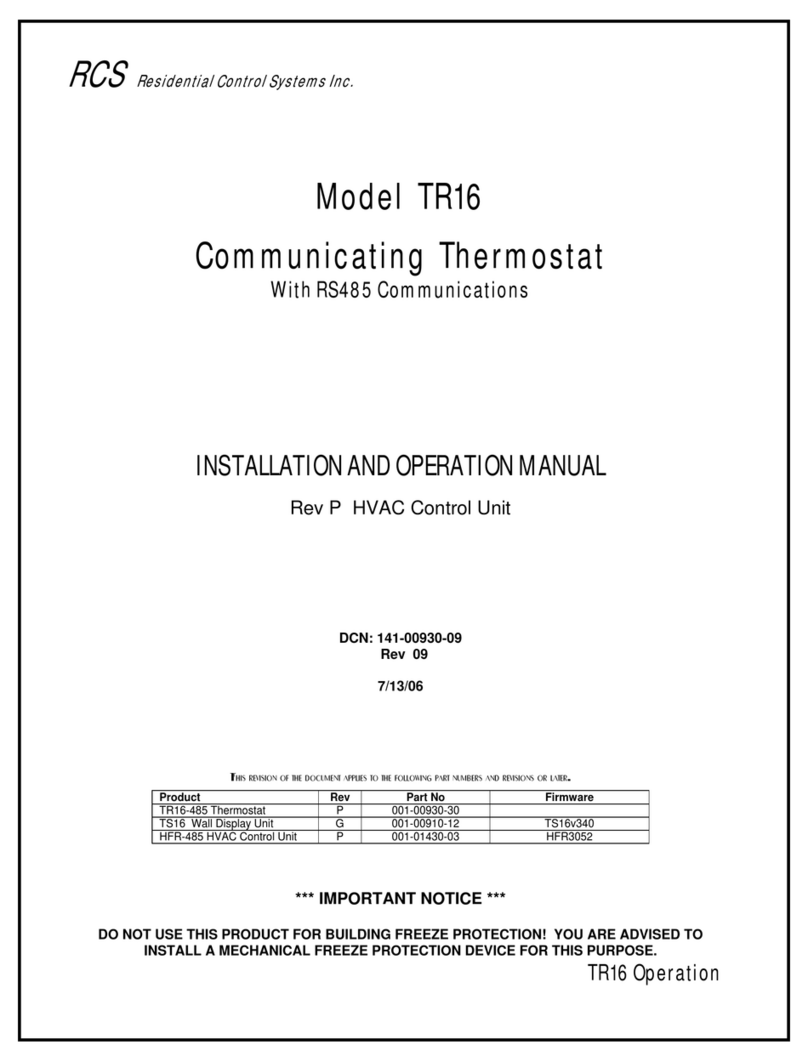
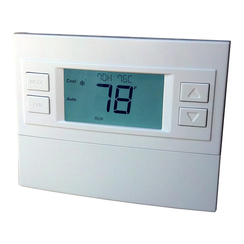
RCS TR16 User manual

RCS
ModelTR16
CommunicatingThermostat
WithRS485SerialCommunications
QUICKSTARTGUIDE
This quick start guide provides basic connection information.
The CD included with this product contains the following
documentation and programs:
• TR16 Installation and Operations Manual
• Serial Communications Protocol Manual
• Thermostat Control Program (TCP)
• TCP Users Manual
Read these documents before attempting to install or use this product
and before calling for technical support.
Additional information may be available at the RCS website: www.resconsys.com
DCN: 140-00930-02
7/13/06

2
TR16 Thermostat kit contents:
1. TS16 Wall Display Unit (WDU)
2. TR16 HVAC Control Unit
3. 120VAC/12VDC 500mA Transformer
4. Quick Start Guide
5. Installation CD
Installation
1. Read the Installation Manual on the CD.
2. Perform the BENCH TEST It is HIGHLY RECOMMENDED that the thermostat be BENCH
TESTED before it is installed on the wall. Setup and connect the WDU and Control Unit, following the
wiring guide, wiring diagram and setup instructions, with a short (1-3 ft) piece of 4 conductor wire (any
wire, 22ga or larger, cat 3/5 or thermostat wire will do for this test).
DO NOT connect the HVAC system thermostat wires at this time (RC/RH, G, W, O, Y1, or Y2).
Double check the wiring connections. Caution! mis-wiring the WDU to Control unit can damage the WDU.
Connect the 12VDC power transformer to the control unit.
Power up the unit and observe the WDU screen. Following the initial startup version number screens, the
room temperature will be displayed.
Observe the HVAC control unit. The Status LED should be flashing slowly.
If “CF” appears on the WDU screen it indicates that the WDU and Control Unit cannot communicate with
each other. Double-check your wiring connections on the WDU and Control unit. Do not proceed until
the wiring is corrected and room temperature is displayed.
Press the fan mode button on the WDU. The Fan mode indicator (middle decimal point) should come on
in the WDU screen and the FAN LED on the control unit should come on. Press the fan button again and
the fan mode indicator and the FAN LED will go off.
These tests verify the WDU and Control Unit power up operation and communications between them.
It is advised that you take the time, while the system is on the “bench”, to familiarize yourself with the
WDU screens and thermostat operations. Refer to the Operations manual on the CD for complete
thermostat information.
3. Set the Network Address
Set the thermostat network address (default 1) by pressing and holding the MODE button and the FAN
button simultaneously on the TS16 WDU. The screen will change to SU (set up). Release the buttons.
Ad (address) will appear. Using the UP/DOWN buttons, set the address to the desired network address.
Screen will timeout and return to normal room temperature display after 5 seconds. See the operations
manual for details.
4. RS485 Communications Test
You can test the thermostat RS485 communications using a PC and the RCS Thermostat Control
Program (TCP) if you are using the RCS RS232/RS485 converter. See the TCP manual.
If you are connecting to another RS485 network, it is recommended that you establish network
communications during this Bench Test. It is much easier to troubleshoot network connections with both
the WDU and Control Unit together on the bench.

The Bench Test is complete! Proceed with actual thermostat installation and
connect the remaining wiring to the HVAC system.
TR16 Control Unit Wiring Guide
Wall Display Unit Connection (J1)
Connect the WDU to the Control Unit J1, using Cat3/5 22/24 Ga twisted pair wiring (recommended) or
typical HVAC thermostat wire (18/20 Ga). Connect according to wiring diagram.
Caution: Miswiring the WDU to Control unit connections may result in damage to the WDU.
12VDC Power to the Control Unit (J4)
Connect the external 12VDC, 500mA transformer provided to jack J4. This is a center ground connector.
HVAC System Connection (J5)
Determine the HVAC System type, Standard Gas/Electric or Heat Pump. Refer to the specific HVAC
system type wiring diagram in the Installation Manual. Use typical 18/20GA thermostat wire. Standard
thermostat wiring labels and typical wire colors:
W is the stage 1 Heat output. White wire.
G is the Fan output. Green wire.
Y1 is stage 1 Compressor output. Yellow wire.
O is the Heat Pump Changeover valve output. Orange wire. (can be Brown)
(O terminal can be used for W2, 2nd stage heat output for standard HVAC systems)
Y2 is the 2nd stage compressor output. Black wire
NOTE: when using existing thermostat wires, don’t assume wire colors are correct, check the
HVAC system end also.
HVAC Transformer Connections 24RH and 24RC
Single Transformer HVAC Systems
Most central HVAC systems have a common heating and cooling system transformer. This is the default
configuration of the Control Unit’s HVAC Systems 24RH and 24RC terminals and they are connected
together by a red jumper wire. This jumper MUST be installed. 24R wiring from the HVAC system can
be connected to either the RH or RC terminals.
Separate Heating and Cooling Transformer HVAC Systems
If the Heating/Cooling system has separate heating and cooling transformers, you MUST REMOVE the
red jumper wire between RC and RH on the control board. Connect the cooling system transformer to
RC and the heating system transformer to RH.
NOTE: With separate transformer systems, the Fan (G) terminal is connected to the RC
transformer.
Set Dipswitch SW1
Set Dipswitch SW1 on the TR16 HVAC Control Unit for the correct HVAC system configuration.
HVAC System Type: Standard Gas/Electric or Heat Pump.
Also set the Fan type for Standard systems or the Changeover Valve type for Heat Pumps systems.
IMPORTANT: SW1 MUST be set to the correct HVAC type for proper HVAC system operation!
RS485 Network Connection (J3)
The TR16 RS485 communications network is a 2 wire, half duplex network. Connect the RS485 network
connection J3 T+ and R- to the network Data + and Data – wires. Always wire RS485 connections + to +
and – to – regardless of labels (B+/D+/T+). Network ground wire is advisable.
3

RCS
TR16 Thermostat Wiring Diagram
4
C - 24VAC Common
Y2 – Comp Stage 2
HVAC SYSTEM
Y1 – Comp Stage 1
G – Fan
THERMOSTAT CONNECTOR
W2/O* – Heat Stage2
W1 – Heat Stage 1
R - 24VAC Return
* for HP HVAC Systems
O=Changeover Valve
TS16
WALL DISPLAY UNIT
Cut Jumpe
r
to split
S2
OFF ON
2
S1 1
SW1
J2
RS485
GND
D -
D +
HEAT1
HEAT2
CO
FAN
COMP1
COMP2
STATUS
HFRU REV P
RH=RC
JP1
TR16 CONTROL UNIT
Rev P
Red
Green
White
Yellow
Orange
24V RC
G
W1
Y1
W2 / O*
24V COM
Y2
24V RH
J4
HVAC SYSTEM
J1
WDU
12V
GND
D
C
GND G
+12VDC +V
CLOCK C
DATA D
Fuse
Mini ATO
2 Amp
Blue
RS485 Gnd
RS485 Data+
RS485 Data -Black
Optional RS485 RJ45
Connector Pinout
1 Data+
2 Data -
3 NC
4 NC
5 NC
6 NC
7 NC
8 GND Front View
12345678 Typical Thermostat wiring colors.
Optional RS485
RJ45 Jack
HVAC System Transformer:
Most central HVAC systems have a common heating and cooling transformer. This is the factory default
setting for Jumper JP1. In some cases, you may have separate heating and cooling systems, each with their
own transformer. In that case, cut Jumper JP1 and wire the heating transformer red wire to the RH terminal
and the cooling system transformer red wire to the RC terminal. Wire the cooling system’s 24VAC Com to the
control unit’s 24VAC Com terminal.
Dipswitch SW1 Settings: (White is switch position)
SW1-S1, STANDARD OR HEAT PUMP SYSTEM SELECTION
SW1-S2 Fan or Change Over Valve Selection
HVAC Systems can be either Standard Gas/Electric systems or Heat Pump systems.
Set S1 to OFF for Gas/Electric systems (default setting).
Set S1 to ON for Heat Pump systems
If S1 is set to Off for Standard HVAC systems, then S2 selects the HVAC fan type.
Set S2 to OFF for gas systems that do not require Fan w/heat calls.(default setting)
Set S2 to ON for electric systems.
If S1 is set to On for HP HVAC systems, then S2 selects the changeover or reversing valve type.
Set S2 to OFF for changeover with cooling (default setting).
Set S2 to ON for changeover with heating
Other manuals for TR16
1
Other RCS Thermostat manuals
Popular Thermostat manuals by other brands

Charmeg
Charmeg MP-R user manual

dixell
dixell WING XW40LS Installing and operating instructions

Network Thermostat
Network Thermostat NetX X7C-WIFI Installation and programming manual

Radio Thermostat
Radio Thermostat CT80 Operation guide

HAI
HAI Omnistat RC-120 installation manual

Lennox
Lennox iComfort E30 Installation and setup guide

Lux Products
Lux Products PSD011Ba Installation and operating instructions

Computherm
Computherm Q20 operating instructions

Heatmiser
Heatmiser neoStat user manual

Mars
Mars HEAT CONTROLLER IR Wireless Thermostat user manual

LUX
LUX LP0511D user manual

Saswell
Saswell SAS920XWHB-7-S-RF User manual and warranty card

