manuals.online logo
Brands
  1. Home
  2. •
  3. Brands
  4. •
  5. RDL
  6. •
  7. Recording Equipment
  8. •
  9. RDL RACK-UP Series Guide

RDL RACK-UP Series Guide

RACK-UP®SERIES
Model RU-ADL2
Professional Audio Delay
Studio Quality, Low Noise DSP Audio Delay
Separate Time Delays for Two Audio Outputs
Adjustable Delay from 0 to 135 mS
Large Numeric Display of Time Delay
Keyboard Style Buttons to Adjust Time Delay
Fully Remote Controllable Audio Delay
Provision to Disable Front Panel Adjustment
XLR and Terminal Block Audio Connections
Exclusive RDL
Sure-Lok
™ Supervision
The RU-ADL2 is part of the group of RDL RACK-UP products. The compact design permits high-density installations, with three products mounted in
a single rack unit. The RU-ADL2 may be used alone, or mounted using a wide variety of RACK-UP series options.
The RU-ADL2 is a DSP based dual-output delay for an analog audio source. 96 kHz sampling provides exceptional audio
performance for the most critical applications in a professional audio environment. Proprietary RDL
Sure-Lok
circuitry and coding
supervises audio and data signals for the accuracy and stability demanded in professional installations.
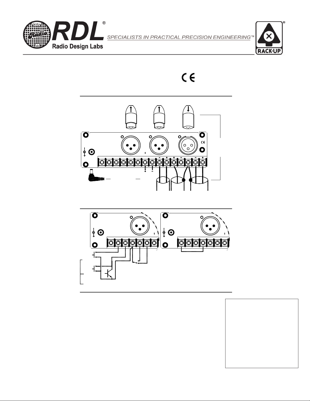
APPLICATION: The RU-ADL2 is the ideal choice in most applications where one or two delayed balanced or unbalanced line-level
signals are required. All audio connections are made through XLR connectors or on full sized barrier block terminals provided on the
rear panel. The RU-ADL2 may be used as a standalone delay, or its input may be connected in parallel with multiple
RU-ADL2 modules to provide additional delayed outputs.
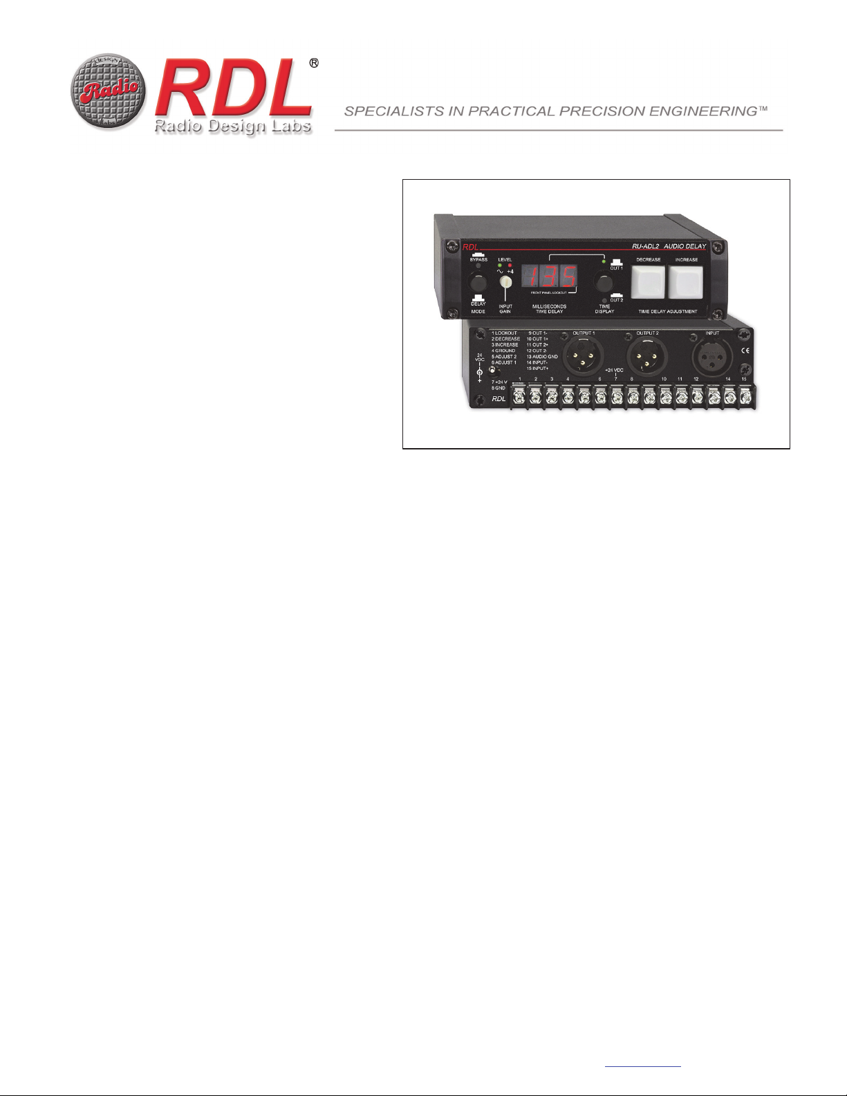
The RU-ADL2 accepts a single monaural audio input and provides two separate monaural outputs. The time delay on each output is
individually adjustable from 0 to 135 mS. A large, bright 3-digit LED numeric display on the front panel shows the time delay set for
each of the two outputs. A locking pushbutton switch selects the output to be displayed and adjusted. Time adjustment is made
using durable keyboard style pushbuttons on the front panel. A separate button is provided to increase or decrease delay. Pressing
a button will change the time delay in 1 mS increments. If a button is held, the time will first ramp slowly, then more rapidly permitting
easy coarse and fine adjustment of the time delay. A locking pushbutton permits the user to completely bypass the DSP time delay
section without losing the stored delay values.
Rear panel terminals provide full remote control of the RU-ADL2. Each function is activated by pulling the associated terminal to
ground, either through a switch or open-collector circuit common to RDL modules and many OEM products. The output to be
adjusted may be selected by remote control, then the time delay for that output may be ramped up or down. Time delay values are
stored in non-volatile memory so the RU-ADL2 returns to the correct settings following any interruption of power. In fixed
installations, it is often desirable to set the correct delay times and not permit user adjustment of these values. After initial setup, the
installer may connect a jumper from the LOCKOUT terminal to ground to disable the operation of the front-panel time adjustment
buttons. Those buttons remain disabled and the LOCKOUT indicator remains illuminated until the jumper is disconnected. The
front-panel time display and BYPASS buttons remain active when the LOCKOUT jumper is installed.
The INPUT GAIN is adjustable and is equipped with a front-panel dual-LED LEVEL meter that follows standard VU ballistics.
A green LED illuminates at 15 dB below +4 dBu, becoming progressively brighter with increasing audio level. The adjacent red LED
illuminates when the audio level exceeds +4 dBu. The output levels are fixed at nominal unity gain. The RU-ADL2 operates from
ground-referenced 24 VDC power, connected either to barrier block terminals or through a power jack on the rear panel.
The easy front-panel time adjustment makes the RU-ADL2 ideal in studio, remote or satellite downlink applications requiring manual
synchronization of audio with video. The small size of the RU-ADL2 accommodates portable use in temporary sound reinforcement
applications. The front-panel lockout provision is ideal in many fixed sound installations. Mounting options and studio-quality audio
performance make this module the ideal choice in a wide variety of systems. Wherever an economical yet superior performance line-
level audio delay is needed to provide synchronization, speaker array time alignment, acoustic effects or feedback suppression, the
RU-ADL2 is the ideal choice.
RDL 659 6th St. Prescott, AZ., USA 86301 (928) 443-9391 FAX (928) 443-9392 www.rdlnet.com
RACK-UP®SERIES
Model RU-ADL2
Professional Audio Delay
24
INPUTOUTPUT 2OUTPUT 1
8 GND
7 +24 V
6 ADJUST 1
5 ADJUST 2
4 GROUND
3 INCREASE
2 DECREASE
1 LOCKOUT 9 OUT 1-
10 OUT 1+
11 OUT 2+
12 OUT 2-
13 AUDIO GND
14 INPUT-
15 INPUT+
1 2 3 4 6 7 8 10 11 12 14 15
+24 VDC
RDL
VDC
SOURCE
POWER
24 VDC
2 DECREASE
3 INCREASE
8 GND
RDL
VDC
24
7 +24 V
4 GROUND
5 ADJUST 2
6 ADJUST 1
1 LOCKOUT
11 OUT 2+
15 INPUT+
14 INPUT-
13 AUDIO GND
12 OUT 2-
1234 6
+24 VDC
7
10 OUT 1+
9 OUT 1- OUTPUT 1
BALANCED
FROM
SIGNAL
SOURCE
AUDIOLINE-LEVEL
EQUIPMENT
UNBALANCED
FEEDING
SIGNAL
DELAY2DELAY1
BALANCED
SIGNAL
FEEDING
LINE-LEVEL
EQUIPMENT
SIGNAL 1
DELAYED
SIGNAL 2
DELAYED SIGNAL
SOURCE
BLOCK
OR TERMINAL
CONNECTOR
AUDIO USING
CONNECT
CONNECT
POWER USING
BLOCK
OR TERMINAL
CONNECTOR
INPUT AND EACH OUTPUT MAY BE
CONNECTED BALANCED OR UNBALANCED
SWITCH SELECTS
WHICH OUTPUT
TIME DELAY MAY BE
REMOTELY ADJUSTED
1
2
2 DECREASE
1 LOCKOUT
RDL
7 +24 V
8 GND
24
VDC 5 ADJUST 2
6 ADJUST 1
4 GROUND
3 INCREASE
OUTPUT 19 OUT 1-
4321
11 OUT 2+
14 INPUT-
13 AUDIO GND
12 OUT 2-
10 OUT 1+
15 INPUT+
76
+24 VDC
DECREASE
INCREASE
EACH REMOTE FUNCTION MAY BE CONTROLLED BY SWITCHES OR OPEN COLLECTORS.
(DISABLE) FRONT-PANEL TIME ADJUSTMENT.
INSTALL JUMPER AS SHOWN TO LOCK OUT
FRONT-PANEL DISPLAY, DISPLAY SELECTION AND
BYPASS SWITCHES WILL REMAIN ACTIVE.
MOMENTARY CONNECTION TO GROUND ADJUSTS DELAY TIME
CONTROL
WIRING
POWER
WIRING
AUDIO AND
GND
TYPICAL PERFORMANCE
Line Input: +4 dBu nominal, 40 kbalanced (may be connected unbalanced)
Maximum Line Input Level: +26 dBu
Gain Adjustment: Off to 16 dB gain
Frequency Response: 20 Hz to 20 kHz (+/- 0.5 dB)
THD+N: < 0.05%
Residual Noise (below +4 dBu output): < -80 dB
Outputs (2): +4 dBu nominal, 150 balanced (may be connected unbalanced)
Delay Adjustment Range: 0 to 135 mS in 1 mS steps
Propagation Delay: None (1 to 135 mS delay); 180 uS (0 mS delay)
Headroom (above +4 dBu output): >18 dB
Indicators (5): Dual-LED VU meter for input
LOCKOUT indicator
BYPASS indicator
TIME DISPLAY (2)
Display: 3 digit display, Height: 0.4 in. (1 cm); 0 to 135 mS in 1 mS increments
Power Requirement: 24 Vdc @ 275 mA, Ground-referenced
Overall Dimensions: Height: 1.7 in. 4.3 cm
Length: 5.8 in. 15.0 cm
Depth: 5.3 in. 13.4 cm
Installation/Operation
Declaration of Conformity available from rdlnet.com.
Sole EMC specifications provided on product package.
Specifications are subject to change without notice.
891-3205E
Radio Design Labs Technical Support Centers
U.S.A. (800) 933-1780, (928) 778-3554; Fax: (928) 778-3506
Europe [NH Amsterdam] (++31) 20-6238 983; Fax: (++31) 20-6225-287
NOTE: This equipment has been tested and found to
comply with the limits for a Class B digital device, pursuant
to part 15 of the FCC Rule. These limits are designed to
provide reasonable protection against harmful interference
in a residential installation. The equipment generates,
uses and can radiate radio frequency energy and, if not
installed and used in accordance with the instructions,
may cause harmful interference to radio communications.
However, there is no guarantee that interference will not
occur in a particular installation. If this equipment does
cause harmful interference to radio or television reception,
which can be determined by turning the equipment off an
on, the user is encouraged to try to correct the
interference by one or more of the following measures:
Reorient or relocate the receiving antenna
Increase the separation between the equipment
and receiver
Connect the equipment into an outlet on a circuit
different from that which the receiver is
connected.
Consult the dealer or an experienced radio/TV
technician for help.

This manual suits for next models

1

Other RDL Recording Equipment manuals

RDL SYS-CS1 User manual

RDL

RDL SYS-CS1 User manual

RDL RM Series Guide

RDL

RDL RM Series Guide

RDL FLAT-PAK Series User manual

RDL

RDL FLAT-PAK Series User manual

RDL DD-BTN44 Guide

RDL

RDL DD-BTN44 Guide

Popular Recording Equipment manuals by other brands

Fractal Audio MFC-101 MARK III owner's manual

Fractal Audio

Fractal Audio MFC-101 MARK III owner's manual

TS-market EMM Tiny Stereo 1120 quick start guide

TS-market

TS-market EMM Tiny Stereo 1120 quick start guide

Lance Design ADX-2400D Installation and operation manual

Lance Design

Lance Design ADX-2400D Installation and operation manual

Philips CDR560BK Specifications

Philips

Philips CDR560BK Specifications

MEM DSP1024 owner's manual

MEM

MEM DSP1024 owner's manual

Yamaha CDR-D651 owner's manual

Yamaha

Yamaha CDR-D651 owner's manual

LogTag Recorders LTI-WM-WiFi Product user guide

LogTag Recorders

LogTag Recorders LTI-WM-WiFi Product user guide

Brainstorm SR-112 owner's manual

Brainstorm

Brainstorm SR-112 owner's manual

Allen-Bradley 1770-KFD Installation instructions manual

Allen-Bradley

Allen-Bradley 1770-KFD Installation instructions manual

Demedash Effects T-120 Deluxe Videotape Echo v2 instruction manual

Demedash Effects

Demedash Effects T-120 Deluxe Videotape Echo v2 instruction manual

HME TI7000 Quick Reference Installation Guide

HME

HME TI7000 Quick Reference Installation Guide

Harman JBL VTX Series user guide

Harman

Harman JBL VTX Series user guide

Abatron BDI2000 user manual

Abatron

Abatron BDI2000 user manual

Roland DIF-AT owner's manual

Roland

Roland DIF-AT owner's manual

Nektar Aura owner's manual

Nektar

Nektar Aura owner's manual

Camille Bauer EMMOD201 V2.0 manual

Camille Bauer

Camille Bauer EMMOD201 V2.0 manual

Apollo REACH WIRELESS RW1700-030APO quick start guide

Apollo

Apollo REACH WIRELESS RW1700-030APO quick start guide

Behringer MAGICIAN T1950 user manual

Behringer

Behringer MAGICIAN T1950 user manual

manuals.online logo
manuals.online logoBrands
  • About & Mission
  • Contact us
  • Privacy Policy
  • Terms and Conditions

Copyright 2025 Manuals.Online. All Rights Reserved.