manuals.online logo
Brands
  1. Home
  2. •
  3. Brands
  4. •
  5. Connects2
  6. •
  7. Recording Equipment
  8. •
  9. Connects2 CTSIV008 User manual

Connects2 CTSIV008 User manual

CTSIV008
Steering Wheel Control
Interface
for Iveco Vehicles
APPLICATION
FEATURES
• Allows for the installation of a double DIN aftermarket stereo
• Retains factory steering wheel control functionality
• Retains factory phone buttons
• Provides outputs for speed pulse, reverse gear and park brake
The information provided in this document is subject to change without notice due to manufacturer changes and/or improvements to the product/s. This
instruction manual is based on documented data and research. The manufacturer of this product cannot be held responsible for any changes made to the
vehicle by the manufacturer or damages that may occur through the installation of this product in accordance with the steps outlined herein.
DISCLAIMER
CTSIV008_IG_v1
Iveco Daily 2023 >
Note: Application data is subject to change at any time
Note: vehicle will need modication. Please familiarise yourself with the instructions before undertaking installation.
2CTSIV008_IG_v1
WIRING KEY
STEERING WHEEL CONTROL FUNCTIONALITY
1. Track Up
2. Track Down
3. Source
4. Volume Up
5. Volume Down
6. Mute
7. Pick Up (Short Press)
Hang Up (Long Press)
8. Speech
1
25
7
4
6
8
Front
Back
3
PRODUCT INFORMATION
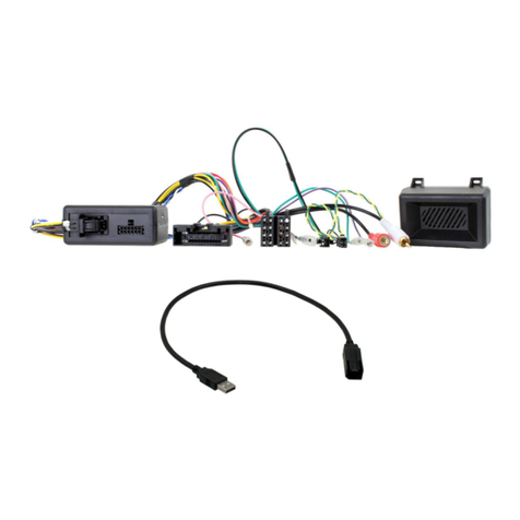
The CTSIV008 is a CAN steering wheel interface and harness which helps retain the steering wheel
controls and factory phone button functionality of the vehicle (if vehicle is equipped). The harness also
allows for the retention of the original reversing camera. The lead features plug-and-play connectors for an
easier installation process.
Please note: This interface is designed for vehicles with the basic headunit.
IN ISO CONNECTOR
Purple Right Rear Speaker +
Purple/Black Right Rear Speaker -
Green Left Rear Speaker +
Green/Black Left Rear Speaker -
Grey Right Front Speaker +
Grey/Black Right Front Speaker -
White Left Front Speaker +
White/Black Left Front Speaker -
ADDITIONAL CONNECTIONS
Pink Speed Pulse
Green Park Brake
Purple/White Reverse Gear
Yellow Permanent 12V
Black Ground
Red Ignition 12V
Orange Illumination
The following diagram, though based on careful research, is an example only. Individual steering wheel control congurations may differ.
3CTSIV008_IG_v1
Need help? Visit support.connects2.com/tickets/technical
WIRING DIAGRAM
ISO Connector
Connect to aftermarket stereo
Connect to relevant connector from vehicle
Stereo Connection (Patch)
Lead Connector [12 Pin]
Connect to Interface Box
before power connection is
made to the interface
Main Wiring Loom
Connector [14 Pin]
Connect to Interface Box
Interface Box
Flying Wires
Pink - Speed Pulse
Green - Park Brake
Purple/White - Reverse Gear
Fakra Antenna Connection
Connect to OEM Antenna connector from vehicle
FM/Blue Phantom Power Connections
Connect to aftermarket stereo
4CTSIV008_IG_v1
7. Connect the vehicle specic connector to the vehicles main power connector.
8. Test stereo and steering wheel control functionality for correct operation before reassembling the
vehicle dashboard. If steering wheel control functions are unresponsive, please uninstall the interface and
wiring and reinstall carefully in accordance with the above steps.
For further help, please contact and ll out a support ticket with the full details of your issue at:
support.connects2.com/tickets/technical
6. Attach the antenna adapter in between the vehicles pre-existing connector as well as the rear of the
aftermarket head unit.
NOTE: If vehicles which feature an amplied aerial, the blue wire will be needed for purposes of phantom power.
INSTALLATION GUIDE - WIRING See wiring diagram on Pg.4 for more information
Before installing the interface, the factory stereo must be removed and disconnected. To do this, please consult the vehicle
owner’s manual/handbook or contact a tting professional.
For universal patch leads, prepare the wiring loops in accordance with the instruction manual supplied before installation.
1. Connect the 12 Pin connector from the stereo connection (patch) lead to the interface box.
2. Connect the opposite end of the stereo connection (patch) lead to the steering wheel control input on
the back of the aftermarket stereo.
NOTE: This may be a 3.5mm jack connector or a wired input depending on the brand of aftermarket stereo being tted. Please consult the
aftermarket stereo installation manual for further information on where to make the connection.
IMPORTANT: THIS STEP MUST BE COMPLETED BEFORE CONNECTING POWER TO THE INTERFACE.
FAILURE TO DO SO MAY RESULT IN A LACK OF FUNCTIONALITY AND THE NEED TO REINSTALL THE PRODUCT.
!
3. Connect the 14 Pin connector from supplied wiring loom to the interface box.
4. Connect the power/speaker ISO connector to the power/speaker ISO connector at the rear of aftermar-
ket stereo.
Note: For aftermarket stereos which do not have an ISO connector, please see ‘Wiring Key’ on Pg.2 for information on which wires to connect.
5. Connect any additional ying wires from the harness to the head unit as required.
Note: Additional ‘flying’ wires can be connected to the vehicle to support various features i.e. parking brake trigger, reverse gear and speed
pulse. Details of these can be found under ‘Additional Connections’.


Other Connects2 Recording Equipment manuals

Connects2 CAM-VW6-AD User manual

Connects2

Connects2 CAM-VW6-AD User manual

Connects2 CTSPO003.2 User manual

Connects2

Connects2 CTSPO003.2 User manual

Connects2 Vision CAM-TY5-RT User manual

Connects2

Connects2 Vision CAM-TY5-RT User manual

Connects2 Vision CAM-VL1-AD User manual

Connects2

Connects2 Vision CAM-VL1-AD User manual

Connects2 CTSFO017.2 User manual

Connects2

Connects2 CTSFO017.2 User manual

Connects2 Aerpro CHFO17C User manual

Connects2

Connects2 Aerpro CHFO17C User manual

Connects2 CAN CONNECT CANHBAU2 User manual

Connects2

Connects2 CAN CONNECT CANHBAU2 User manual

Connects2 CTUPO02 User manual

Connects2

Connects2 CTUPO02 User manual

Connects2 FK-555-4 User manual

Connects2

Connects2 FK-555-4 User manual

Connects2 Vision CAM-LR6-AD User manual

Connects2

Connects2 Vision CAM-LR6-AD User manual

Connects2 CAM-AU1-AD User manual

Connects2

Connects2 CAM-AU1-AD User manual

Popular Recording Equipment manuals by other brands

Seca 460 quick start guide

Seca

Seca 460 quick start guide

Roland MT 120 owner's manual

Roland

Roland MT 120 owner's manual

Tews Technologies TPMC465 user manual

Tews Technologies

Tews Technologies TPMC465 user manual

Harman Kardon CDR 30 owner's manual

Harman Kardon

Harman Kardon CDR 30 owner's manual

Yamaha MDR-1 Handling instructions

Yamaha

Yamaha MDR-1 Handling instructions

powersoft DSP4 Series Service manual

powersoft

powersoft DSP4 Series Service manual

Mitsubishi Electric 16CH DIGITAL RECORDER DX-TL5000U user manual

Mitsubishi Electric

Mitsubishi Electric 16CH DIGITAL RECORDER DX-TL5000U user manual

GAI-Tronics 370-901 manual

GAI-Tronics

GAI-Tronics 370-901 manual

Saramonic SmartRig+ user manual

Saramonic

Saramonic SmartRig+ user manual

Motrona BY 125 operating instructions

Motrona

Motrona BY 125 operating instructions

ORTEC 99X-1 instruction sheet

ORTEC

ORTEC 99X-1 instruction sheet

IntesisBox MH-RC-BAC-1 quick start guide

IntesisBox

IntesisBox MH-RC-BAC-1 quick start guide

SEW-Eurodrive DFP21B manual

SEW-Eurodrive

SEW-Eurodrive DFP21B manual

HMS Networks Intesis INKNXDAL0640200 user manual

HMS Networks

HMS Networks Intesis INKNXDAL0640200 user manual

PAC GM3A-RSTX manual

PAC

PAC GM3A-RSTX manual

Bastl Propust user guide

Bastl

Bastl Propust user guide

GU Electronic MB 2015 PAS instruction manual

GU Electronic

GU Electronic MB 2015 PAS instruction manual

Miller Electric Remote Operator Interface owner's manual

Miller Electric

Miller Electric Remote Operator Interface owner's manual

manuals.online logo
manuals.online logoBrands
  • About & Mission
  • Contact us
  • Privacy Policy
  • Terms and Conditions

Copyright 2025 Manuals.Online. All Rights Reserved.