RDS loadmaster 9000i User manual

Loadmaster 9000i DMM
Approved Weighing System
Operation
RDS Part No.:
Document Issue:
Software Issue:
S/DC/500-10-589
1.1: 3/9/08
PS 306-050 rev. 20

CONTENTS
2
Electromagnetic Compatibility (EMC)
This product complies with Council Directive 89/336/EEC
when installed and used in accordance with the relevant
instructions.
Service and Technical Support
PLEASE CONTACT YOUR NEAREST DISTRIBUTOR
If unknown then fax +44 (0) 1453 733311 for further
information.
Our policy is one of continuous improvement and the
information in this document is subject to change
without notice.
Check that the software reference matc
hes that
displayed by the instrument.
© Copyright RDS Technology LTD 2008
\UK589110.DOC

CONTENTS
3
1OVERVIEW __________________________________________________________5
1.1 Introduction............................................................................................................................................................... 5
What is the difference between these two Approvals? ........................................................................................... 5
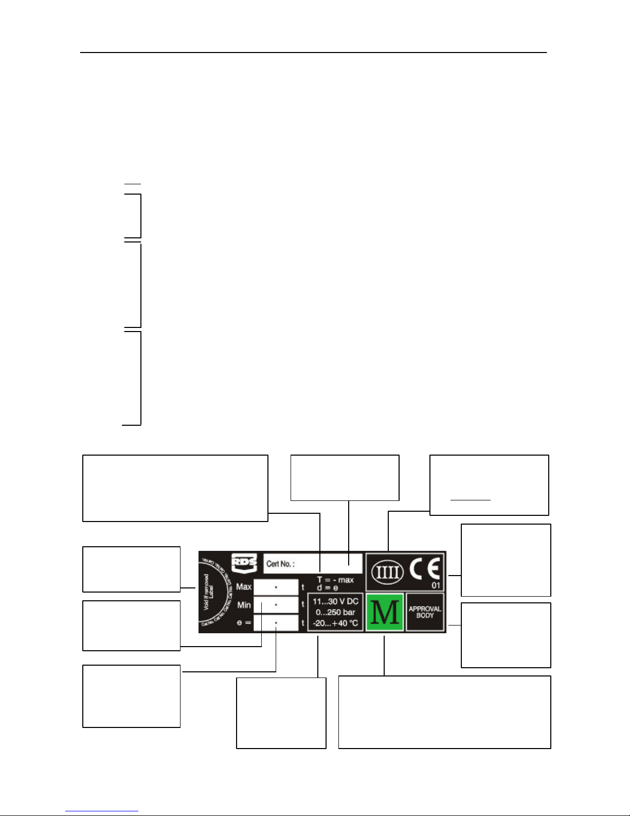
1.2 System Technical Details ......................................................................................................................................... 5
1.3 Calibration................................................................................................................................................................. 6
1.4 Weighing Units.......................................................................................................................................................... 6
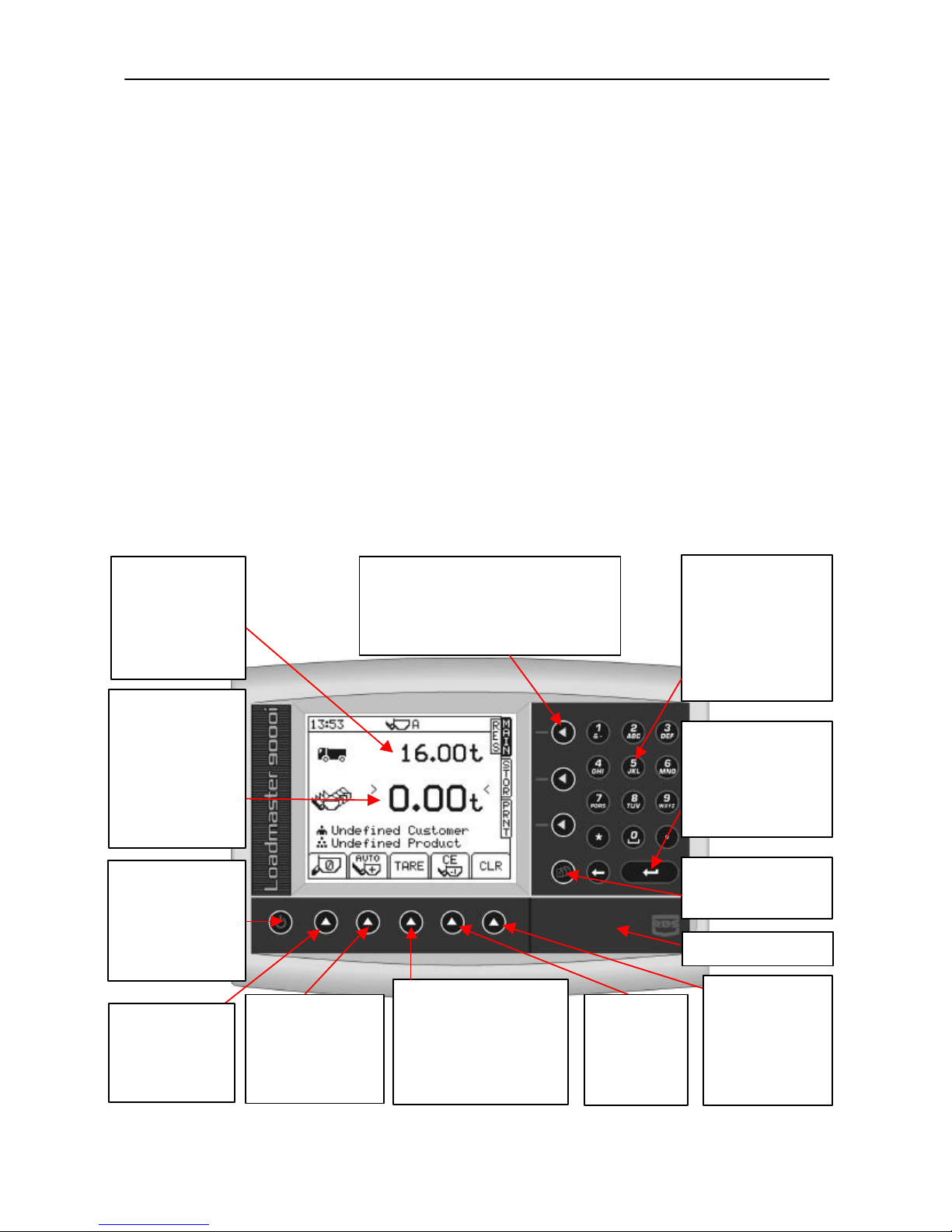
1.5 The Head Unit........................................................................................................................................................... 6
1.6 Approved Weighing Mode Certification................................................................................................................... 7
1.7 Loading Attachments................................................................................................................................................ 8
1.8 Menu keys................................................................................................................................................................. 8
1.9 Data Entry.................................................................................................................................................................. 8
2STARTUP ___________________________________________________________9
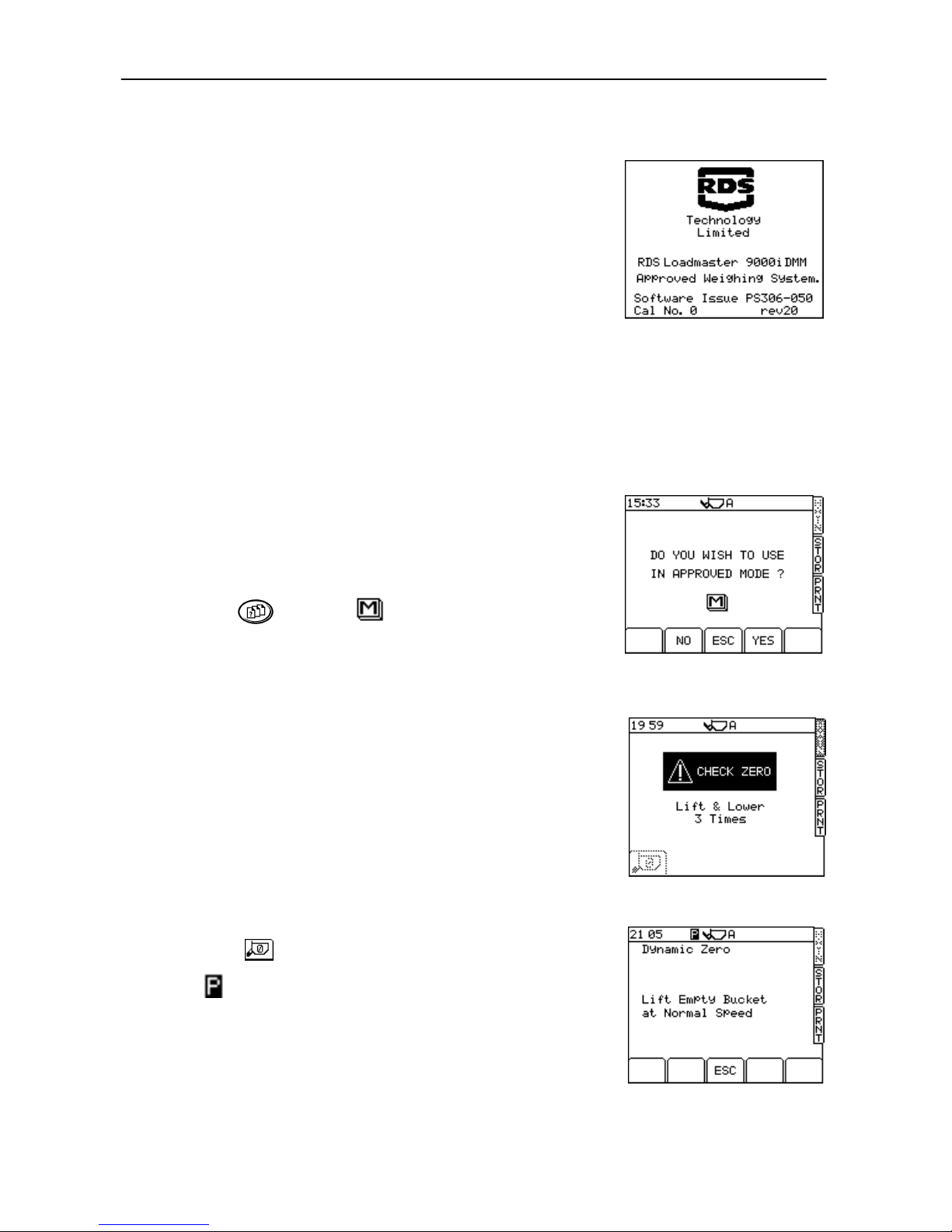
2.1 Switch On.................................................................................................................................................................. 9
2.2 Set Weighing Mode.................................................................................................................................................. 9
2.3 Zero Prompt .............................................................................................................................................................. 9
2.4 Zero ........................................................................................................................................................................... 10
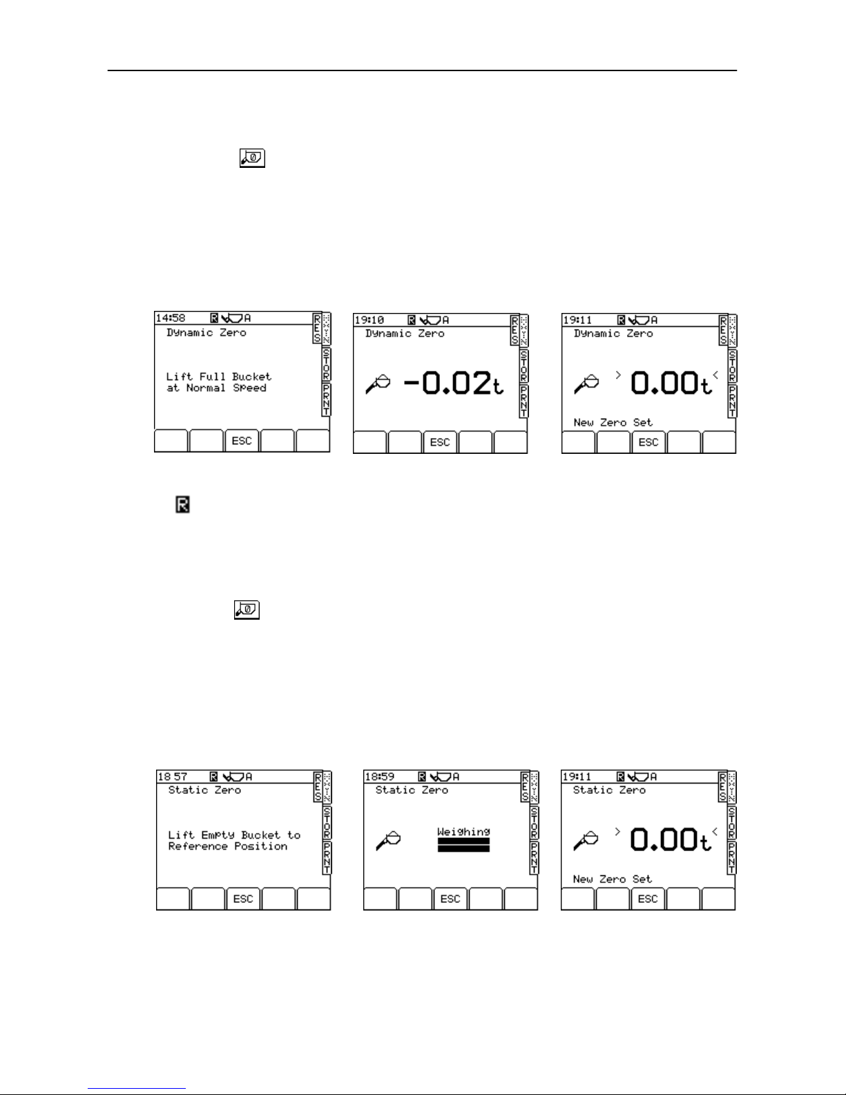
2.4.1 Dynamic Zero (Dynamic Mode)................................................................................................................ 10
2.4.2 Static Zero (NAWI Mode)........................................................................................................................... 10
2.4.3 Error Messages.......................................................................................................................................... 11
(i) Angle of Slope............................................................................................................................................ 11
(ii) Low Oil Temperature / Sensor Faults ....................................................................................................... 11
(iii) Crowd Bucket............................................................................................................................................ 11
(iv) Boom Sensor (Telehandlers only)............................................................................................................ 11
2.5 Set Target Load......................................................................................................................................................... 11
2.6 Set Preset Tare.......................................................................................................................................................... 11
2.6.1 Cancel Preset Tare .................................................................................................................................... 11
2.6.2 Re-weigh function (Tare –1)...................................................................................................................... 12
2.7 Set the Load Enter mode (AWI only)....................................................................................................................... 12
3WEIGHING IN APPROVED MODE ______________________________________13
3.1 Dynamic Weighing ................................................................................................................................................... 13
3.2 "Live Last Bucket" Weighing (Dynamic only).......................................................................................................... 13
3.3 Static Weighing......................................................................................................................................................... 14
3.4 Selecting Stores Index.............................................................................................................................................. 15
3.4.1 Store Index Search Function .................................................................................................................... 15
3.4.2 Set Target Weight ...................................................................................................................................... 16
3.5 Error Messages......................................................................................................................................................... 16
3.5.1 Angle of Slope............................................................................................................................................ 16
3.5.2 Low Oil Temperature / Sensor Faults ....................................................................................................... 16
3.5.3 Anti-bounce................................................................................................................................................ 16
3.5.4 Maximum Weight Exceeded ..................................................................................................................... 16
3.6 Zero Alarms............................................................................................................................................................... 16
Zero Limit Exceeded (more than ±2% drift)............................................................................................................ 16
Zero Error (more than ±10%) ................................................................................................................... 17
3.7 Clear Last Entry......................................................................................................................................................... 17
3.8 Reset for next load.................................................................................................................................................... 17

CONTENTS
4
4STORE FUNCTIONS _________________________________________________18
4.1 Stores Setup.............................................................................................................................................................. 18
4.1.1 Hardware Setup -Data Module................................................................................................................. 19
4.1.2 Hardware Setup -ICP 300 Printer............................................................................................................. 19
4.1.3 Software Setup for Printers (in Approved Mode) ..................................................................................... 19
4.1.4 Data Card Compatibility and Formatting.................................................................................................. 21
4.1.5 Data Card files required to enable the Store Functions........................................................................... 21
4.1.6 Enable Store Functions............................................................................................................................. 21
4.2 Programming Stores Data (Files REFDAT01 -REFDAT06) via a PC ..................................................................... 22
4.3 Programming Stores Data (Files REFDAT01 -REFDAT06) via the Head Unit....................................................... 23
4.4 How to read the Load Data file (LM9KTOTL.CSV).................................................................................................. 24
4.5 How to read the Print Log file LM9KPLOG.CSV ..................................................................................................... 25
4.6 Search / Print Load Records.................................................................................................................................... 26
4.6.1 Select Printer Output Mode....................................................................................................................... 26
4.6.2 View / Print Last Load Record................................................................................................................... 26
4.6.3 View / Print Multiple Load Records........................................................................................................... 27
4.6.4 View / Print / Clear the Grand Total .......................................................................................................... 28
4.6.5 Overload logging facility............................................................................................................................ 29
4.6.6 View / Print the 7-day Total ....................................................................................................................... 29
4.6.7 View Data Card Status............................................................................................................................... 29
5SYSTEM SETTINGS MENU ____________________________________________30
5.1 Adjusting Screen Contrast or Brightness ................................................................................................................ 30
5.2 Set Time and Date .................................................................................................................................................... 30
5.3 Switch Tare Facility Off............................................................................................................................................. 30
5.4 Set Instrument ID...................................................................................................................................................... 31
5.5 Job/Ticket Number................................................................................................................................................... 31
5.6 Change PIN Numbers.............................................................................................................................................. 31
5.7 Set Language............................................................................................................................................................ 32
5.8 Module Check .......................................................................................................................................................... 32
6. OTHER INFORMATION SCREENS______________________________________32
6.1 'Diagnostics............................................................................................................................................................... 32
6.2 'Helpline' .................................................................................................................................................................... 32
6.3 Serial Numbers ......................................................................................................................................................... 32
6.4 Approval Status......................................................................................................................................................... 32
7. LOADMASTER CONFIGURATION FILE (LMSETUP.CSV) __________________33
7.1 Editing the Header information on the Printout....................................................................................................... 33
Document History.................................................................................................................................................................... 34

1 -OVERVIEW
5
1.1 Introduction
The Loadmaster 9000i DMM is designed for Weights and Measures approved operation, for either automatic weighing
(AWI) or non-automatic weighing (NAWI).
The relevant Trading Standards Type Approval is: -
?? Class IIII OIML R76 (EN45501) Directive 90/384/EEC for a non-automatic weighing Instrument (NAWI).
?? OIML R51 European Type Approval Agreement (WELMEC) for an automatic weighing instrument (AWI).
The system can also operate in a Non-Approved weighing mode i.e. as a Loadmaster 8000i instrument. Switching
between Non-Approved Mode and Approved Mode (NAWI or AWI depending on the installation setup) can be done by
the operator as required, however, the Secondary Software Module must be installed to access the Approved Mode.
The instrument is based primarily on the Loadmaster 8000i weighing system. Two pressure sensors are mounted on
each side of the hydraulic lift system. They provide an increase of frequency signal as the load increases. The average
frequency is captured at a set weighing point provided by the Reference/Direction sensor assembly. Calculated with a
factor, the system weighs the contents in the bucket being lifted. This information can then be saved to a certain
customer or product memory store.
This instruction manual covers operation for NAWI and AWI weighing modes. It does not cover use in non-approved
weighing mode. For non-approved weighing, please refer to the Loadmaster 8000i instruction manual.
What is the difference between these two Approvals?
CLASS IIII (NAWI) -This is a European Approval allowing the use of the LM 9000i in any EEC country for sale of
goods, with no further Approval required from the Trading Standards Body in the relevant EEC Country. Mode of
operation is "Non-Automatic" and therefore Static weighing procedure should be used, using Manual confirmation of
the displayed weight.
CLASS Y(b) (AWI) -This is a UK Approval allowing the use of the LM 9000i in the UK for sale of goods. Use of this
instrument in other EEC countries with this Standard is possible, providing Approval has been acquired from the
Trading Standards Body in the relevant EEC country. Contact your local RDS Distributor for the relevant details. This
"Automatic" mode allows both Dynamic or Static operation, together with Automatic entry of the displayed weight.
1.2 System Technical Details
?? 6 User-definable store entries with extended reference capability
?? Hydraulic Pressure Sensing Technology
?? Angle Sensing Technology (compensation & inhibition)
?? Automatic Dynamic Weighing System with 2 arms
?? Static weighing
?? Temperature sensing inhibition
?? Forward Speed Inhibition (optional)
?? Bucket crowd inhibition
?? ICP and memory card compatible
?? Memory Store Upload Facility
?? Anti Bounce Inhibition.

1 -OVERVIEW
6
1.3 Calibration
For approved mode operation, all calibration is done on installation prior to NAWI or AWI certification. No further
calibration is permissible.
For calibration in non-approved mode, please refer to the Loadmaster 9000i Calibration manual.
1.4 Weighing Units
For NAWI and AWI approved modes: The units are 't' for tonnes or "kg" for kilograms, with a resolution ('e') according
to the certification as defined on the label on the head unit
In non-approved mode: Metric or imperial units (kgs, tonnes, m3, UK tons, US tons, lbs), and the resolution can be
selected via the 'CALIBRATION' menu. If weighing volumetrically, you must set the density.
On a Loadmaster 8000i, the units are normally displayed on screen and on printouts. If a Loadmaster 9000i Class IIII
approved weighing system is used in non-approved weighing mode (i.e. as a Loadmaster 8000i), then units are not
displayed on screen or included on a printout in compliance with the requirements for Weights and Measures Approval.
Also, the text "Not for Trade use or Applications under Article 1.2(a) 90/384/EEC" will appear on every printout.
1.5 The Head Unit
Figure 2
“Target load”
You want this load to
load on the vehicle.
As you load, the figure
will decrease to show
how much is left to
load.
“Return to MAIN Screen”
Press at any time to return from the Tare screen
or any other screen, back to the MAIN weighing
screen displayed here.
Numeric Keypad
Used to enter a 'Target
Load'. If the Target Load
displayed is incorrect, just
type in a new one,
finishing with the Enter
key.
Use also for keying in a
Preset Tare value.
“Power On / Off“
Button
Turns the Loadmaster
on and off. Note that
this unit is also
switched through the
loader’s ignition key.
“Weight in bucket”
and “Total loaded so
far”
This shows the weight
in the bucket and then
the total loaded,
starting at 0.00 and
increasing as you load,
to show how much has
been loaded so far.
TARE Button
Optional TARE entry facility
subtracting a set value to
provide a NET Weight.
Press and hold until the Tare
window appears, then enter
the tare value required
“Setup” Button
Not used when loading.
SD/MMC Card Reader
“Clear Totals” Button
Press and hold for 1
second to clear the
'Total Loaded' and
'Left to Load' figures
before starting to load
a new vehicle.
Automatic / Manual
Weight Entering
Depending on
Certification.
Selectable in Non-
Approved Mode
“Zero Button”
Press to select the
Bucket Zero screen
when you want to
zero the bucket.
“ENTER” Button
When you have typed in a
new Target Load, press
this button to enter it.
Also used to set in the
Bucket Zero.
“Clear Last
Entry”
Press to delete
the last entry and
restore the
previous tota
l

1 -OVERVIEW
7
1.6 Approved Weighing Mode Certification
There are currently 2 main Approval Certifications: -Class IIII -NAWI (Non-Automatic weighing Instrument) and y(b) -
AWI (Automatic Weighing Instrument). Within each Approval type (Class IIII or y(b)), the Loadmaster 9000i can be
certified for maximum weights from 1 to 25 tonnes. For ease of setup, the instrument is configured for certification in the
range 1 to 15 tonnes via a menu of 18 presets (see below). It is also possible to configure the Loadmaster 9000i for any
maximum weight from 16 to 25 tonnes, but not via presets.
Presets (Class IIII and y(b)):
Max weight: Resolution (e):
1000 kg 10kg (10e)
2000 kg
3000 kg 20kg (20e)
4000 kg
5000 kg
5000 kg
6000 kg
7000 kg
8000 kg 50kg (50e)
9000 kg
10000 kg
11000 kg
12000 kg
10000 kg
11000 kg
12000 kg
13000 kg
14000 kg 100kg (100e)
15000 kg
17000 kg
20000 kg
25000 kg
Figure 3a
Verification Scale Interval
in decimal tonnes, (the
resolution to which the
system has been
verified).
Area reserved for a
"CALIBRATION VOID IF
BROKEN" sticker
"T" = Subtractive Tare: A tare figure can be entered
up to the Maximum weight that the system is
verified to (i.e.: -max).
"d" = Actual Scale Interval (that displayed on-
screen) = Verification Scale Interval ("e")
Certification number given
after initial verification for the
system (Pattern Number)
The Class IIII Symbol,
demonstrating th
at this system
is a Trading Standards
Approvable NAWI/AWI
"CE" mark
demonstrates that this
system has passed the
EMC regulations and
other applicable CE
directives
Position for the number
of the Approval Body
carrying out the field
verification
(Also see below)
The Type
Approval sticker for Class IIII (NAWI) certification
is placed here (the "Metrologie symbol).
R51 y(b) (AWI) certification does not require a type
approval sticker, however, the Approval Body carrying out
the field verification may place their mark here or in the
"APPROVAL BODY" box to the right.
System Environmental
Parameters: -
Supply voltage
Load Sensor Pressure
Temperature
Maximum and Minimum
weigh
t that the system is
verified to (decimal
tonnes).
The certification details are given on the plate fixed on the left
hand side of the Head Unit (fig. 3a), The label is completed with
the certi
fication details, after field verification of the weighing
system by the local approval body.

1 -OVERVIEW
8
1.7 Loading Attachments
The system can be calibrated for up to 8 different attachments.
1.8 Menu keys
Nine menu keys adjacent to the LCD display access all instrument
functions.
The four menu keys to the right of the screen access the primary screen
pages (those viewed during normal operation). There are three primary
screens MAIN, STOR and PRNT for normal operating functions, and a
SETUP screen for calibration functions.
The five sub-menu keys below the screen control the various display
functions and settings for each of the primary screen pages. Text or
icons are displayed adjacent to the sub-menu keys to denote their
function.
1.9 Data Entry
Alphanumeric values are entered via the right-hand keypad. You must
press the key from 2 to 5 times to select the required letter. (Some keys
have additional special characters not shown on the key legend).
The key will either toggle between lower and upper case characters
or when preceding a numerical entry, will set a MINUS value.
The key will toggle between 0 and a SPACE.
The key will BACKSPACE the screen cursor if you need to re-enter a
character.
The key is the RETURN key and is normally pressed to
confirm the data entry into memory.

2 -STARTUP
9
2Startup
Before you start to load you need to check a few things,
?? Select Approved or Non-approved mode
?? Work the hydraulics to get up to normal operating temperature,
otherwise the screen displays the message "Oil too Cold" and weighing
is inhibited.
?? Set Zero Weight
?? Set the Target load.
?? Set Preset Tare (if required)
?? Set Load Enter Mode
?? Set the Customer and/or Product Store to which totals will be recorded
(section 4).
2.1 Switch On
On switch on, the following screen is shown (fig. 4).
The Cal No. is zero after a software reset. It increments each time the
calibration is entered by using the FACTORY PIN number.
NOTE: THIS NUMBER SHOULD MATCH THE NUMBER ON THE PLATE ON THE
SIDE OF THE INSTRUMENT. IF NOT, LOCAL CERTIFICATION HAS BEEN
VOIDED.
2.2 Set Weighing Mode
Press the key then the key (fig. 5).
The instrument prompts you to choose the approved mode (NAWI / AWI)
or non-approved mode.
Press 'YES ' or 'NO' and wait as the instrument is re-configured. You must
zero after selecting the weighing mode.
NOTE: Please refer to the Loadmaster 8000i manual for weighing in non-
approved mode.
2.3 Zero Prompt
The "CHECK ZERO" screen (fig. 6a) occurs if the system has been
switched off or has not recognised any lifts for more than 15 minutes.
Three beeps occur and are repeated every 60 seconds thereafter when
in this state.
Lift and lower the empty bucket 3 times. "Lift & Lower 3 Times" is
prompted, with the number shown, and decrements one number after
each lift has been achieved. When the third lift has been completed,
press the button and the screen automatically moves to the
"Dynamic Zero" screen (with AWI set-up) or "Static Zero" screen (NAWI).
The symbol (fig. 6b) denotes that this is the first dynamic/static zero
after switch-on.
After the first 10 minutes from switch on, when the first "CLR" is
performed, the "CHECK ZERO" routine must be repeated, and again
after another 10 minute period has passed. After that, the routine should
occur every 30 minutes.
Figure 6b
Figure 6a
Figure 5
Figure 4 UK589-04/PCX

2 -STARTUP
10
2.4 Zero
2.4.1 Dynamic Zero (Dynamic Mode)
Pressing the key displays the "Dynamic Zero" screen when
dynamic weighing is selected in AWI mode (fig. 7).
Lift the empty bucket at medium lift speed. The weight will display very
briefly and then the instrument zeros automatically before returning to
the MAIN screen. The ">" and "<" signs (fig. 9) confirm that the
instrument has zeroed to with 0.25e, i.e.: -
-for 2000kg certification, "e" = 20kg, zero is within ±5kg.
-for 5000kg certification, "e" = 50kg, zero is within ±12.5kg.
-for 10000kg certification, "e" = 100kg, zero is within ±25kg.
The symbol denotes that this is a zero done during normal operation.
NOTE: If the "live last bucket" is used, the dynamic zero is followed by the static
zero (as described below).
2.4.2 Static Zero (NAWI Mode)
Pressing the key displays the "Static Zero" screen (fig. 10) if the
Loadmaster is in NAWI Mode (or if static weighing is selected in AWI
mode).
Raise the bucket to the reference position. The loader kickout operates,
stopping the lift. A short delay will occur as a weight reading is taken
(fig. 11). The instrument will then sound a single bleep and zero
automatically before returning to the MAIN operating screen.
The ">" and "<" signs (as in fig. 9) confirm that the instrument has
zeroed to with 0.25e as for dynamic zero.
Figure 7
Figure 8 Figure 9
Figure 10 Figure 11 Figure 12

2 -STARTUP
11
2.4.3 Error Messages
(i) Angle of Slope
This indicates that the angle of slope is too great in a particular direction
-move to a more level area.
(ii) Low Oil Temperature / Sensor Faults
The instrument also warns you of low oil temperature or a sensor fault
and inhibits the zero routine.
(iii) Crowd Bucket
You must crowd the bucket right back before weighing can take place.
(iv) Boom Sensor (Telehandlers only)
You must retract/extend the boom to the correct position.
2.5 Set Target Load
You want this weight to load on the vehicle (fig. 13).
From the MAIN screen, simply key-in the target weight and then press
the ENTER key to confirm. As you commence the loading cycle, the
figure will decrease to show how much is left to load.
2.6 Set Preset Tare
This facility is used to display the NET weight of a product within a lifted
container. The normal gross weight is taken, from which the pre-
programmed empty weight of the container is automatically subtracted.
From the MAIN screen, press and hold the TARE key (fig. 14). Key-in the
empty container weight and press ENTER to confirm.
The Preset Tare (PT) is then displayed on the MAIN screen (fig 15a).
With a tare set, each bucket weight is displayed with the symbol
above it (fig. 15a) and any printout will be identified with the letters
The Tare facility may be switched off from the SYSTEM SETTINGS menu
in which case the TARE key will no longer appear on the screen.
2.6.1 Cancel Preset Tare
To CANCEL a preset tare, simply press and hold the TARE key again,
then release. After a few seconds the "Tare" window will disappear,
canceling the preset tare setting.
Figure 13
Figure 14
Figure 15a

2 -STARTUP
12
2.6.2 Re-weigh function (Tare –1)
The loader operator may wish to tip a partial amount off the last bucket load to “top-off” the truck load. The
“re-weigh” function enables the weight of this surplus material to be subtracted from the truck total, ensuring
the recorded total matches the actual weight loaded into the truck.
The re-weigh function must be enabled from the SETUP menu (ref. section 5.3).
1. Lower the bucket load with the remaining material.
2. Press the “Tare –1” key (fig.15b).
3. Lift to re-weigh and then press ENTER. The remaining material weight is then subtracted from the total.
2.7 Set the Load Enter mode (AWI only)
The Load Enter mode should normally be set to . The load will be automatically entered as the bucket
is lifted above the weighing position.
Alternatively, if you prefer to manually enter the bucket weight on every lift, then hold the SUB MENU key to
select .
Figure 15b Figure 15dFigure 15c

3 -WEIGHING
13
3Weighing in Approved Mode
In approved mode (NAWI or AWI), weighing will be inhibited unless the
machine is up to normal operating temperature and the bucket is
crowded right back. These restrictions do not apply in non-approved
mode. The system also has several compensatory features allowing for
varying lift speed, weighing 'on the move', and weighing on a slope
while maintaining the accuracy required. Warnings will be displayed if
you exceed the operating parameters of the system.
3.1 Dynamic Weighing
With dynamic weighing, the load is lifted without any interruption.
Weighing can be fully automatic and quick,. and weighing 'on the move'
is possible.
Fill the bucket as normal and crowd it right back. Hold the lift lever
back. Lift the bucket smoothly at a constant speed through the
reference position, keeping the loader as steady as possible while the
weight is taken.
If the display shows this indicates that the lift speed was
too slow -try again.
If the display shows this indicates that the lift speed was
too fast -try again.
Avoid excessive bounce if weighing on the move. The system is
designed to compensate for vehicle movement within certain limits,
beyond which a warning is displayed and weighing is inhibited.
The bucket weight is then displayed (fig. 17) and if AUTO
ENTER is set (as shown), the weight is automatically stored in memory.
If MANUAL ENTER is set, then PRESS the LOAD ENTER BUTTON to
store the weight reading in memory.
The target weight will decrease by the bucket weight to show
how much is left to load (fig. 18).
The figure then indicates the total of all bucket weights
entered so far. Continue loading until you get to the last bucketful.
3.2 "Live Last Bucket" Weighing (Dynamic only)
The "live last bucket" mode must have been enabled from the SETUP
menu.
Lift the arms up to the weighing position and the instrument then
switches automatically to "last bucket" static weighing mode. When the
target weight is reached or surpassed, the bucket weight display will
flash and the display will give a "live" readout. You can tip off a little as
required, allowing the live display to settle down.
YOU CANNOT MANUALLY ENTER THE LAST BUCKET WEIGHT.
Instead, lower the bucket and then lift dynamically. The final bucket
weight is then automatically added to the total.
NOTES: The ">" and "<" signs (figure 16) confirm the instrument is zeroed to
within 0.25e (Section 2.4.1, where 'e' = Scale Interval.).
For AWI only, if the individual bucket weight is below the minimum
weight specification, the calculated lift weight will NOT be added to the
totals. The screen will display the message "Below Minimum Weight".
Figure 16
Figure 17
Figure 18

3 -WEIGHING
14
3.3 Static Weighing
This uses the loader's auto-kickout system to automatically stop the lift
arms in the reference position before sampling the weight.
The weighing screen (fig. 19) will appear the same as for AWI Mode,
other than that AUTO ENTER is not selectable.
Fill the bucket as normal and crowd it right back. Pull the lift lever back
to it's held position. As the loader reverses the bucket will come up to
the weighing point and the lift lever kickout will operate automatically.
NOTE: Best accuracy is achieved with the vehicle stationary. The system will
display a warning if excessive movement occurs, and weighing will be
inhibited.
Keep the loader as steady as possible while the weight is taken.
The display will show two ‘bars’, which fill up, indicating that the weight
is being sampled (fig. 20) and the bucket weight is then
displayed.
There is no AUTO ENTER option. The weight reading will be logged
and stored only when the LOAD ENTER button is pressed.
As with dynamic weighing, when the bucket weight is entered, the
target weight figure will decrease by that amount.
Continue loading until you get to the last bucketful. The instrument
does not switch to 'last bucket' Static weighing mode as it does in non-
approved Mode. Instead, if the last bucket weight is more than the
target weight, the bucket weight will start flashing. Either press the
REMOTE ENTER BUTTON to enter the weight, or lower the bucket
below the reference/direction sensor to cancel it.
NOTE: The ">" and "<" signs (figure 19) confirm the instrument is zeroed to within 0.25e (Section 2.4.1).
Figure 19
Figure 20

3 -WEIGHING
15
3.4 Selecting Stores Index
Until a data card containing the reference files is inserted into the Data Module, the instrument will alternately
display a black screen and the message "Data Card Module Needed".
1. Select the STOR screen, then select the index required for store 1, using the key or the search function
(fig. 21a).
NOTE: Press to go step back 1 index, or press the’0’ key to return to Index '0'.
2. Press the ENTER key to confirm the store 1 entry and select store 2 (fig. 21b).
3. Repeat step 2 for further stores as applicable.
NOTE: Only the stores enabled from the 'Stores Setup' screen (section 4.1.6) will appear above.
On confirming the last store, the instrument then reverts to the MAIN screen. Only the first 3 stores can be
displayed.
On completing the load, when the CLR button is pressed the load data is automatically saved to the data card.
3.4.1 Store Index Search Function
Instead of entering the Index No. , from any of the 'SELECT <Store
Reference>'' screens (figs. 21a -21c), press the key.
Enter one or more characters from the Index name or Extended
reference and press the enter key to begin the search.
Indexes containing those characters are then listed. Select the
appropriate one using the key, and then and press
the key.
If no information matches the search criteria, the screen remains blank.
Figure 21a: (Store Ref 1)
UK506-31.PCX
Figure 21b: (Store Ref 2) UK506-32.PCX
Figure 21c: (Store Ref 3) UK506-28B.PCX
Add new index entry (ref. section 4.3)
Search facility
UK506-31.PCX
Index name
Extended Reference

3 -WEIGHING
16
3.4.2 Set Target Weight
The target weight is set automatically to the value programmed in field 2 of the selected 'Truck' index (a blank
field sets a zero target weight).
After completing the store selection and returning to the MAIN screen, you can manually enter a different target
weight if required.
3.5 Error Messages
3.5.1 Angle of Slope
This indicates that the angle of slope is too great in a particular
direction -move to a more level area.
3.5.2 Low Oil Temperature / Sensor Faults
The instrument also warns you of low oil temperature or a sensor fault
and inhibits the zero routine.
3.5.3 Anti-bounce
Caused by excessive bouncing of the loader whilst weighing. The
screen prompts "To Much Bounce -Lift Again".
3.5.4 Maximum Weight Exceeded
flashes on-screen with a 3-second continuous beep when the
maximum weight limit is exceeded. This will occur 9 divisions (9 x e)
above the stated maximum figure that the system is certified to.
Weighing is inhibited in NAWI or AWI mode.
Example: If Max weight = 10.0t and 'e' = 0.05t,
the Alarm weight = 10.45t.
3.6 Zero Alarms
Zero Limit Exceeded (more than ±2% drift)
When a zero procedure is performed in normal use, the instrument
automatically detects if the Zero readings have moved more than ± 2
%of the maximum weight, from the Zero set at the first Zero after
switch on (fig. 22b).
This prompt is designed to alert the operator that there could be a build
up of material in the bucket, and automatic confirmation of the Zero is
inhibited. Clean out the bucket as necessary.
Example zero limits are:
for 2000kg max. weight: -±40kg
for 5000kg max. weight: -±100kg
for 10000kg max. weight: -±200kg
Figure 22b
If an oil temperature warning
appears, work the machine
for a few minutes until the oil
has reached a suitable
operating temperature.
The error will disappear
automatically at this point.
This prevents errors
occurring with cold oil

3 -WEIGHING
17
Zero Error (more than ±10%)
When the system is initially switched on, or if the unit has not been
used for 15 minutes, the figure resulting from the Zero procedure is
compared to the initial Zero's logged during the systems initial
verification. If these figures are different by more than ±10 % of the
maximum weight, the Zero confirmation will be inhibited, and the
following screen will be shown (fig. 22c).
Example limits are:
for 2000kg max. weight: -±200kg
for 5000kg max. weight: -±500kg
for 10000kg max. weight: -±1000kg
If a "Zero Error" cannot be rectified, re-calibration is necessary.
3.7 Clear Last Entry
If the last bucket weight was entered in error, then press the key to
delete it.
Only the last entry can be cleared.
3.8 Reset for next load
Press the key.
or
Press and hold the LOAD ENTER BUTTON for five bleeps.
The load record is then stored to the pre-selected product / customer
stores.
If the printer mode is set to 'REC' (Record) or 'ROLL' then a printout is
produced automatically when the CLR key is pressed.
The instrument resets to the preset target load. If a different target load is
needed for the next load, simply key-in the new value for the target load
and press the ENTER key.
NOTE: The printer output mode 'OFF', 'ROLL' or 'REC' is selected from the PRNT
screen.
Figure 22c

4 -STORE FUNCTIONS
18
4Store Functions
There are 6 separate Reference stores which to which you can programme whatever information you require
e.g. Customers, Products, etc. All data is stored on the internal SD Card -Data Management Module (DMM),
as .CSV (Comma Separated Variable) text files. No data is held in the head unit memory. The data module
therefore, must be connected and a data card inserted with the correct system files (section 4.1.1), for the
store functions to operate.
New stores information can be added in MS Excel, or via the instrument keypad. Existing store information
however, can only be edited in MS Excel, and not via the instrument. Each store can up to 10,000 entries.
NOTE: Each entry has an "Index No". The index no is the primary reference that the instrument uses to search the
database, for printing a load summary, or saving the store reference data with each completed load. It is the
index no's and not the text entries, that appear in the load data file LMTOTALS.CSV.
?? Once each load is entered, the data (bucket weight, total weight, time/date etc) along with the selected store
reference information (in a shorthand form using just the Index No's of each store) is saved to the data module.
?? Print out a load ticket each time the load is entered.
?? Search the database by store reference, dates, etc and print out a summary of the loads found within your
search criteria.
?? Transfer load records into your own accounting /data management software on the PC, for billing and
traceability purposes.
4.1 Stores Setup
Section 4.1 explains everything you need to know to begin using the store functions on the Loadmaster
including,
?? Hardware Setup -Data Module (4.1.1) and Printer (4.1.2)
?? Instrument Software Setup (4.1.3)
?? Data Card format and file transfer (4.1.4 -4.1.5)
?? Programming your own Stores Data (e.g. Customers, Products etc -4.2, 4.3)
Head Unit Data Module containing database:
Store Ref.1
(REFDAT01.CSV
Index 1. Reference Extended Info
Index 2. Reference Extended Info
Index 3. Reference Extended Info
etc.
Store Ref. 6
(REFDAT06.CSV
Index 1. Reference Extended Info
Index 2. Reference Extended Info
Index 3. Reference Extended Info
etc.
etc

4 -STORE FUNCTIONS
19
4.1.1 Hardware Setup -Data Module
Simply insert a formatted SD card containing the required files (ref. Sections 4.1.4 -4.1.5). Any SD card up to
2Gb is compatible. SD-HD (> 2Gb) cards are not compatible. The SD card is inserted as shown below.
Figure 25: SD Data Card Module
The instrument will take several seconds after switching on to establish communication with the module.
NOTE: Until communication is established with the module the error message “Data Card Module Needed” will be
regularly displayed. If the required files are not found on the inserted card, the error message “Data Card or
File Error” will be regularly displayed.
4.1.2 Hardware Setup -ICP 300 Printer
The top port is factory set for connecting an RDS ICP printer, without further configuration being necessary. If
another printer is used (or you want to select an option other than a printer), you can configure the settings
from the ‘SETUP’ menu. Connect the printer to the TOP port using cable S/CB/268-1-049 that also provides a
power supply from the head unit (fig 25).
NOTE: For more information on the printer, please refer to the ICP300 printer manual.
4.1.3 Software Setup for Printers (in Approved Mode)
From the SETUP menu, press,
The default settings suit the RDS ICP 300 In-Cab Printer. If you are
using an existing printer from another manufacturer, it may operate with
a different protocol. If it does not work with the default settings, please
refer to the printer instructions.
The default settings (fig. 26) are for the RDS ICP 300 In-Cab Printer.
Print Order Setup: See below
Print Control Off = Instrument sends all jobs as a continuous data stream -e.g. when using a
roll printer
On = Instrument sends one job at a time to printer and the operator must manually
initiate the next print job, e.g. when printing individual sheets with an Epson slip
printer.
Print Logo: Off / On : Prints your company logo on a load ticket.
Bucket List: Off / On : Enables an itemised list of each bucket making up a load total.
Baud rate: 110 / 150 / 300 / 600 / 1200 / 2400 / 4800 / 9600 / 19,200 / 31,250 or 38,400.
Figure 26 UK506-26.PCX
3. System Settings
1. Printer Setup (enter PIN)
SD CARD MODULE-GS.JPG

4 -STORE FUNCTIONS
20
Data Bits: 7 / 8
Stop Bits: 1/ 2
Parity: None / Odd / Even
Handshake: RTS / XON
NOTE: Print Inhibit: (LM 9000 y(b) (AWI) mode only). In AWI mode, printing is inhibited when the weight total is less
than 10e, and cannot be added to the totals.
Print Order -Setup
To select the 'Print Order Setup' screen, from the 'Printer Setup' screen (fig. 26), press the key.
Print Order Setup determines the order in which the information is listed on the load ticket. The default order (if
all stores are enabled) is,
1. <Store Reference 1>
2. <Store Reference 2>
3. <Store Reference 3>
4. <Store Reference 4>
5. <Store Reference 5>
6. <Store Reference 6>
7. Weighing Data (Bucket List and Preset Tare if switched on)
8. Date / Time
Using the up/down arrow keys, select the first store and press the
key to confirm. This store reference will appear first on the
ticket. Repeat for the remaining store references in the order you want
them to be listed on the ticket.
'CE Logo Line'
The CE Logo only appears for one of the reference stores on the printout. For example, in Figure 27 the CE
Logo is set to appear next to the 1st reference store ("Product").
For the reference store selected above, you can then set the line position for the CE logo (refer to the following
section).
Reference text order -Setup
For each Reference store listed on the 'Print Order Setup' screen, you
can set the order in which the reference text and extended reference
text fields (i.e. columns 3 and 4 of the table in section 4.2) are listed.
Also, you can set the position of the CE logo on the printout, In figure
28a, the logo is set to print after data field 3 (the reference text line).
With the appropriate store selected on the 'Print Order Setup' screen,
(fig. 27), press the key. The data fields are then displayed for
the selected store.
Using the up/down arrow keys, select the data field that you wish to
appear first on the printout, and then press the key to confirm.
Repeat for the remaining data fields in the order you want them to be
listed on the ticket.
NOTE: Using commas in either column 3 or 4 of the REFDATxx.CSV file will
create up to 4 additional data fields 5 -8 (as shown in fig. 28a)
Data fields 1 and 2 are for the Index No. and the Target Weight
respectively (fig. 28b), and are not printed out.
Figure 27 UK506-27.PCX
UK58928A.PCX
Figure 28a
Figure 28b UK58928B.PCX
Data field 1
Data field 2
Reference Data (Field 3)
Extended Reference Data (Field 4)
This manual suits for next models
1
Table of contents
Other RDS Accessories manuals
Popular Accessories manuals by other brands

Behringer
Behringer F-Control Audio FCA202 operating manual

TeraBee
TeraBee TeraRanger One Installation and operation manual

RME Audio
RME Audio ADI-648 user guide

Honeywell Home
Honeywell Home RDWL515A2000 Installation and operation guide

SensComp
SensComp 600 Series manual

Clifford
Clifford Sense and Tell 4 owner's guide