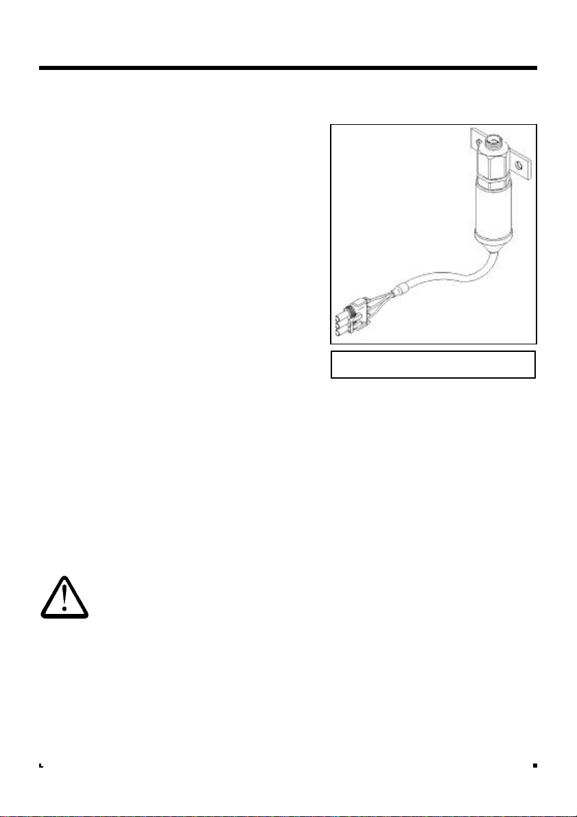
RDS Weighlog 2 User manual

Electro-Magnetic Compatibility (EMC)
This product complies with Council Directive
89/336/EEC when installed and used in accordance
with the relevant instructions.
Service and Technical Support
PLEASE CONTACT YOUR LOCAL DISTRIBUTOR
If unknown then fax: 44 (0) 1453 733311
© Copyright RDS Technology Ltd 2001
Our policy is one of continuous improvement and
the information in this document is subject to
change without notice. Check that the software
reference matches that displayed by the instrument.
Document number
S/DC/500-10-082 : Issue 4 : 12/7/01
\UK082-4.DTP
User Guide
Weighlog 2
Installation
Weighing System
1

1. Overview 3_______________________________
2. Installation 5_______________________________
Important Safety Precautions - 5
*Load (Pressure) Sensor - 6
Reference and Direction Sensor - 10
Remote Enter Switch - 13
Head Unit - 14
Power Supply - 16
External Alarm - 19
Testing the System - 20
*Separate instructions are provided in the case of Strain Sensor installation.
Contents
2

The Weighlog 2 is intended for use on skid-steer loaders, utility tractors with a
loader attachment, wheel loaders, backhoe loaders (loader side only), and
gas powered fork lifts.
It measures, displays and records the net weight lifted, normally based on
sensing the lift system hydraulic pressure. Pressure sensing is problematic on
certain types of equipment due to the design of the hydraulic system. In
these instances strain sensing technology may be used instead.
System Components
Load sensor : This is either a 250 bar rated pressure sensor fitted in the lift
ram hydraulic circuit, or in some instances it is a strain sensor mounted on
the top side of the lift arm (e.g. on certain telescopic loaders).
Reference Position/Direction sensor : The pressure/strain must be
measured with the mechanical linkage in the same position each time. The
reference position/direction sensor is mounted near the lift arm pivot. It
identifies when the lifting attachment is in the correct weighing position, and if
the load is being lifted or lowered. The sensors are triggered by a magnet
mounted on the side of the lift arm.
Remote Enter button: This is mounted next to the lift lever and is used to
record the bucket weight.
Head Unit and wiring: The head unit is supplied with a universal mounting
bracket assembly allowing it to be mounted in almost any configuration.
Overview
3

Overview
The Weighlog system is made up
of a number of standard kits, which
are designed to fit a wide range of
loaders.
Mounting positions will vary ac-
cording to the type of machine,
however this manual gives general
guidelines that apply equally to any
machine.
The installation may require some
modification of the brackets for
mounting the reference/direction
sensor, requiring only basic hand-
tools.
Typical mounting positions are:
1. Pressure Sensor
2. -
3. Reference/Direction
Sensor
4. Magnet
5. Head Unit
6. Remote Enter Button
7. Strain Sensor (Optional)
4

Important safety precautions !
In addition to observing site safety requirements, before working on the
machine always :-
Make sure that the bucket is down on the floor and all pressure is
released from the hydraulic system, before slackening off any hydraulic
coupling.
Prevent the machine from being accidentally started while working on it
e.g. remove the ignition key, place a warning notice in the cab etc.
Keep other persons in the vicinity of the machine fully aware of your
immediate intentions during installation and initial calibration.
Installation
5

Installation
Load sensor
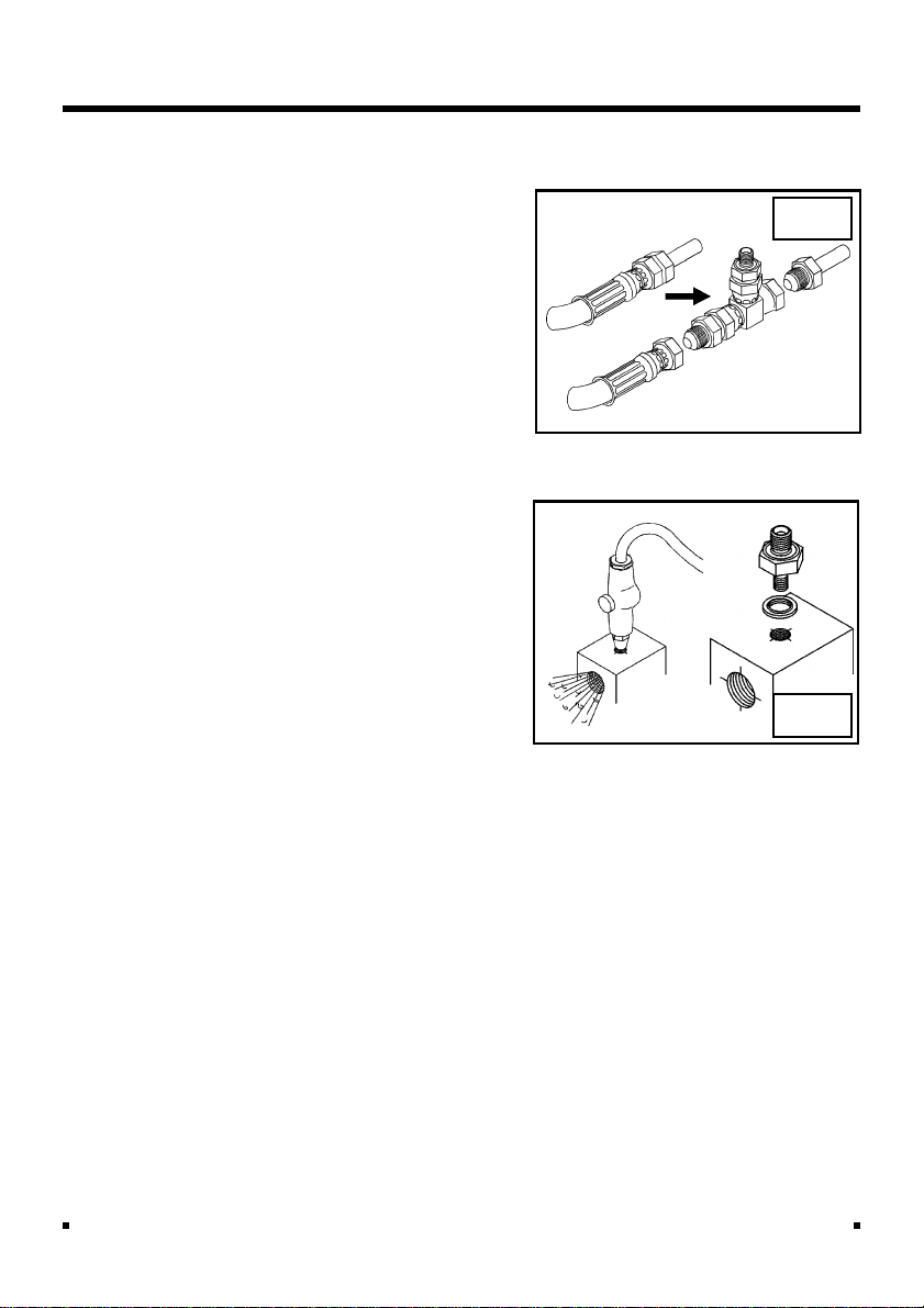
The load sensor (fig. 2) is connected
via a flexible hose into the pressure
side of the hydraulic circuit, using a
tee adaptor fitting.
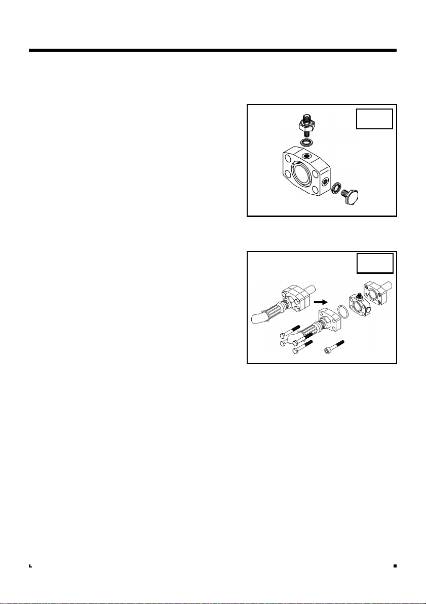
Depending on the machine, you may
be using a threaded teepiece, SAE
flange coupling, or if there is no
suitable coupling you may have to drill
and tap into a suitable point.
The machine is normally specified
when ordering a Weighlog kit so the
correct hydraulic adaptor should be in
the box.
Where to tee-in
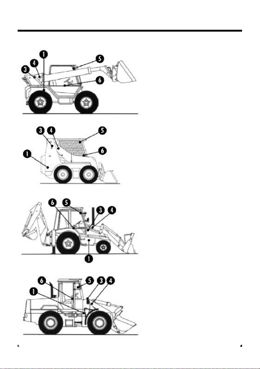
1. Identify the lift hose on one of the
main lift rams. Trace the pipework
back towards the valve block (at some
point the pipework from the other
cylinder will join into a single line).
Identify a suitable coupling which
allows enough room to be split and
the tee adaptor to be inserted, or in
the absence of a suitable coupling, a
point which can be drilled and tapped.
The tee-in points could be anywhere
between the lift cylinder and valve
block but ideally should be as close
as possible to the lift cylinder.
Make sure that the bucket is down
on the floor and all pressure is
released from the hydraulic system,
before slackening off any hydraulic
coupling ! Always loosen or open
the cap on the hydraulic tank to
release any pressure.
2. Thoroughly clean around the tee-in
point before splitting, to prevent the
ingress of dirt.
Fig. 2 : Mk 6 Load Sensor
6

Installation
SAE Flange Coupling
3. Fit the 1/8" BSP - 1/4" BSP Adaptor
and Dowty seal to one of the two 1/8"
BSP ports on the flange. Fit the
blanking plug with Dowty seal to the
remaining 1/8" BSP port (fig. 3).
4. Slacken and remove the four flange
fixing bolts and split the coupling.
Insert the flange plate ensuring that
the 'O' rings are properly seated and
that the 1/4" BSP port is in a
convenient orientation.
5. Replace the hose using the longer
bolts provided in the kit. Take care to
ensure the 'O' rings stay in place.
Check the 1/8" BSP port is oriented to
allow room to connect the hose (fig.
4).
Torque the bolts as per the manufac-
turers recommendation. If this is not
known use the following torques:
¾" flange 21-29 lb-ft 2.8-3.9 kgm
1" flange 27-35 lb-ft 3.6-4.8 kgm
1¼" flange 35-45 lb-ft 4.8-6.2 kgm
Fig. 3
Fig. 4
7

Installation
Threaded tees
BSP, JIC or Metric sizes are available.
Tapped port
In cases where there is no suitable
coupling, you must drill and tap a 1/8"
BSP port into a convenient pipe block.
If possible remove the component to
be drilled.
Centre punch and drill a 3mm pilot
hole. Open out to 8.8mm dia x10mm
deep then tap 1/8" BSP.
Ensure all swarf is flushed out of the
pipework, then fit a 1/8" BSPM - 1/4"
BSPM adaptor using a Dowty seal
between the adaptor and block faces.
(fig. 6).
Fig. 5
Fig. 6
8

Installation
Load Sensor mounting
6. Connect the hydraulic hose to the tee
fitting and route the hose towards the
back of the loader frame. Connect to
the load sensor and mount the sensor
in a well protected position where it
can be easily reached for servicing.
7. With the bucket a few inches off the
ground, gently slacken the hose
connection at the load sensor to bleed
off any air inside.
NOTE: Mount the pressure sensor in a well
protected area, in an upside down
position (fig 6b). This helps prevent air
bubbles hitting and damaging the
diaphragm of the sensor.
Load Sensor connection
7. Connect the extension cable to the
"Weatherpak" connector on the sensor
lead and route inside conduit back to
the Harting connectors.
Cable-tie the conduit securely to
existing hydraulic lines or conduits.
Avoid coiling excess cable - it is best
practice to cut the cable to the
required length and re-crimp.
8. Connect to the GRAY Harting connec-
tor as follows (fig. 7):-
Colour Function Terminal #
Red +V GRAY 4
Blue 0V GRAY 1
Green Signal GRAY 5
NOTE: There is no provision for strain relief on
these connections. It is recommended
that sensor cables are cable-tied
securely out of the way.
Fig. 7 : Load Sensor Connections
Fig. 6b
Red - +V Blue - 0V
Green - Signal
Gray Harting
9

Installation
Reference / Direction sensor
First establish with the operator the
most convenient weighing position to
suit the loading operation. The sensor
and magnet must be arranged so that
the magnet is opposite the sensor
face at the weighing position (fig 10).
The sensor cables are tagged to
identify the sensors - 'R' for the
reference sensor and 'D' for the
direction sensor.
NOTE: If you have to take the sensor clamp
apart, on re-asssembly the reference
sensor must be uppermost.
1. Lift the bucket to the height you want
to be the weighing position.
2. General purpose sensor and magnet
mounting brackets are provided which
can be modified if necessary. The
sensor can be mounted parallel (fig. 8)
or at right angles (fig. 9) to the lift arm.
When deciding how and where to
mount the sensor and magnet, note
that in all cases :-
(a) the sensor must be positioned at least
300 mm (12") away from the lift arm
pivot point (fig. 8 and 9).
(b) the magnet should pass the end of the
sensor, 10 mm (3/8") to 30 mm (1-
1/4") away from it in the orientation
shown (fig. 10).
Take care positioning the brackets
to ensure that they will not foul the
lift mechanism when the arms are
fully raised!
Fig. 8
> 300 mm
Fig. 9
300 mm
Fig. 10
10

Installation
3. Mark the hole positions. Drill and tap 2
holes M8 to attach the sensor bracket,
and 2 holes M6 in the lift arm for the
magnet bracket*.
* In some cases the magnet can be
mounted directly onto the lift arm but
you must fit a fibre washer between
the magnet and the arm.
Do not drill the lift arm above the
center line (neutral axis) of the lift
arm ! (fig. 11)
4. Fit the brackets. Attach the magnet
using the stainless steel setscrew with
the fibre washer between the magnet
and mounting face.
5. Route all cables through the conduit
provided in the kit. Cable tie the
conduit at 300mm (12") spacing
following where possible existing
pipework or cabling. You must pass
the conduit through the chassis pivot
point on articulated loaders (fig. 12).
Do not secure the cables to the
vehicle loom.
6 Assemble the reference and direction
clamp assembly as shown in figure 13.
The bracketing is designed so that the
assembly may be installed to either
side of the machine, by rotating the
angle bracket 90 degrees.
Remove the original M8 bolt from the
green Nylon Clamp, and replace it
with the longer M8 x60 mm, Then
tighten with the sensors in the correct
position.
The clamp with sensors should then
be inserted into the clamp holder, and
tightened into position by using the
M8 nyloc nut supplied.
Fig. 12
Fig. 11
Do not drill above center line!
Fig. 13
Angle Bracket
Clamp Holder
11

Installation
The whole assembly can then be
bolted to the Angle Bracket at the
suitable angle for the specific installa-
tion, using the two M6 x16mm bolts
and nuts provided.
Install the angle bracket as shown in
figure 14.
Ref/Dir Sensor Connection
Connect the extension cable to the
"Weatherpak" connector on the sensor
lead route along with the Load Sensor
Lead back to Harting connectors
Connect to the GRAY Harting connec-
tor as follows;
Colour Function Terminal #
Blue Common GRAY 2
Brown Ref. Sig. GRAY 3
Yellow/Green Dir. Sig. GRAY 6
NOTE: There is no provision for strain relief on
these connections. It is recommended
that sensor cables are cable-tied
securely out of the way.
Fig. 14
Blue - 0V
Gray Harting
Brown -
Ref. Signal
Yellow/Green -
Dir. Signal
Fig. 15 Ref/Dir Sensor Connections
12

Installation
Remote Enter Switch
Mount the Remote Enter Switch either
on the lift lever using a hose clip, or
where it is easily accessible next to the
lift lever (fig. 16).
Route the cable back to the Harting
connectors.
Connection
Connect to the BLUE Harting connec-
tor as follows;
Colour Function Terminal #
Blue 0V BLUE 2
Brown Signal BLUE 6
NOTE: There is no provision for strain relief on
these connections. It is recommended
that sensor cables are cable-tied
securely out of the way.
Fig. 16
Fig. 17 Remote Enter
Switch
Connections
Blue - 0V
Brown - Signal
Blue Harting
13

Installation
Head Unit
Confirm with the machine operator on
where to mount the head unit in the
cab. The head unit must not restrict
the view out of the cab, nor impede
the use of the controls.
The head unit is fitted with a 1 metre
flying lead terminating with a blue
"Harting" plug and a gray "Harting"
plug.
The head unit can be mounted in any
of the positions shown (fig. 18). The
instrument is supplied as standard for
mounting on a horizontal surface. To
rotate the position of the mounting
foot, proceed as follows;
Unscrew the M6 pan head screw on
the back of the instrument and remove
the outer plastic casing (fig. 19).
Rotate the outer casing and refit to the
instrument, taking care to fit the
instrument lead and rubber grommet
back into the slot on the casing (fig.
20).
Fig. 18
Fig. 19
Fig. 20
14

Installation
Fix the mounting plate to the cab with
the self tapping screws provided (drill
size - 5/64") (fig. 21).
Do not drill into a ROPS or FOPS
frame.
If you are fixing the mounting plate to
plastic e.g. the dashboard or other
cab moulding, it is recommended to
use M4 screws with "mudwing"
washers to strengthen the mounting
point.
Panel Mounting
Panel mount using the optional panel
mounting kit ref. K/PNL/MNTD.
Panel mounting requires a circular
cutout 85 mm (3-3/8" Ø).
Fit Harting Connectors
Fit the connector shells as shown (fig.
23). Note that the labels should face
away from the plug.
Fig. 21
Fig. 22
Fig. 23
85 mm
70 mm
15

Installation
Power Supply
The instrument head unit can operate
from a supply voltage of 10 - 30 V DC.
The instrument normally operates from
a 12V supply.
The head unit does not have an
integral On-Off switch, and is normally
powered on via the ignition circuit.
However, a separate toggle switch is
provided in the installation kit should
this be preferred.
Vehicles with Positive Earth or Insulated
Return
It is recommended to convert the
system to negative earth. If this is not
feasible then note that,
(i) The instrument must remain insulated
from the vehicle chassis
(ii) Sensor wiring must not use the chassis
as an earth return, but must be fully-
wired back to the instrument.
12V Systems
Kit Ref: K/INSTRUMENT
1. Connect the power supply lead to the
BLUE Harting connector as follows;
Colour Function Terminal #
Blue 0V BLUE 1
Brown +V BLUE 4
2. Route the power lead back to a
switched, fused point, e.g. from the
back of the ignition switch or from the
fuse box.
Blue - 0V
Brown - +V
Blue Harting
Fig. 24 Power Supply Connection
16

3. Connect the in-line fuse to the brown
wire of the power supply lead using the
male and female crimp provided.
4. Connect the 0V ring terminal to the
bodywork/chassis. Ensure connection
onto bare metal and that the connec-
tion point gives a good grounding path
to the battery.
5. Fit the piggyback crimp connector to
the other end of the fuse, and connect
to the supply point.
NOTE: If required, panel-mount the toggle
switch at a suitable point (1/2" dia drill
required) and connect between the +V
(brown) wire on the instrument end of
the supply lead and the blue Harting
terminal 4, using a suitable length of the
same gauge wire.
Installation
Fig. 25 12V Power Supply
Brown
Blue
Fusebox
Ignition
Switch
17

24V Systems
Kit Ref: K/INST/24V
The latest UDM-J type head unit
operates from 10 - 30V DC, as do the
sensors, therefore a 24V-12V voltage
dropper is not required.
Earlier head units require the voltage
dropper. The wiring scheme is shown
below for reference to older installa-
tions.
Installation
Fig. 26 24V Power Supply
Brown 24V
Blue 12V
Black
Brown
24V - 12V
Convertor
18

Installation
External Alarm
An external alarm is optional. Mount
the alarm buzzer where it will stay dry.
Connect to the BLUE Harting connec-
tor as follows;
Colour Function Terminal #
Blue 0V BLUE 3
Brown +V BLUE 5
Fig. 27 External Alarm Connection
Brown +V
Blue - 0V
Blue Harting
19

Testing the System
1. Switch the power on.
The alarm should beep once and the display will come on.
2. Lift the bucket up to the weighing position.
The alarm should beep once. The display should indicate a number which is
meaningless until the system is calibrated. If the display shows "Err" then
there is no signal from the load sensor.
3. Press the Remote Enter Button.
The alarm should beep once.
This verifies the operation of the system and you should then proceed with
weight calibration.
Installation
20
Table of contents
Other RDS Accessories manuals
Popular Accessories manuals by other brands

Aqua-Marina
Aqua-Marina BREEZE BT-19BRP 2019 user manual

Hunter
Hunter MINI-CLIK installation instructions

Rockler
Rockler Chrome Summit Pen Kit instructions

Saxun
Saxun KIARA Technical manual

EMX Industries, Inc.
EMX Industries, Inc. IRB-325 operating instructions

Summit Treestands
Summit Treestands Climbing System instructions

Datalogic
Datalogic BASIC HOLDER Use and Installation Instructions

Sonotec
Sonotec SONOCHECK ABD06 Series operating manual

Anti
Anti Senior Folding Goal 750 Assembly instructions

Awarepoint
Awarepoint S2 installation manual

Infinite
Infinite L-com SRCN-C415-2 user guide

Cassia
Cassia Personal Safety Sensor user guide