Re US3 User manual

.ENG.
US3
Ultrasonic sensor
USER’S MANUAL


Re S.p.A. US3
I
Contents
Warnings ........................................................................................................................................... 1
Ultrasonic sensor advantages........................................................................................................ 2
Ultrasonic sensor limitations.......................................................................................................... 2
Typical applications......................................................................................................................... 2
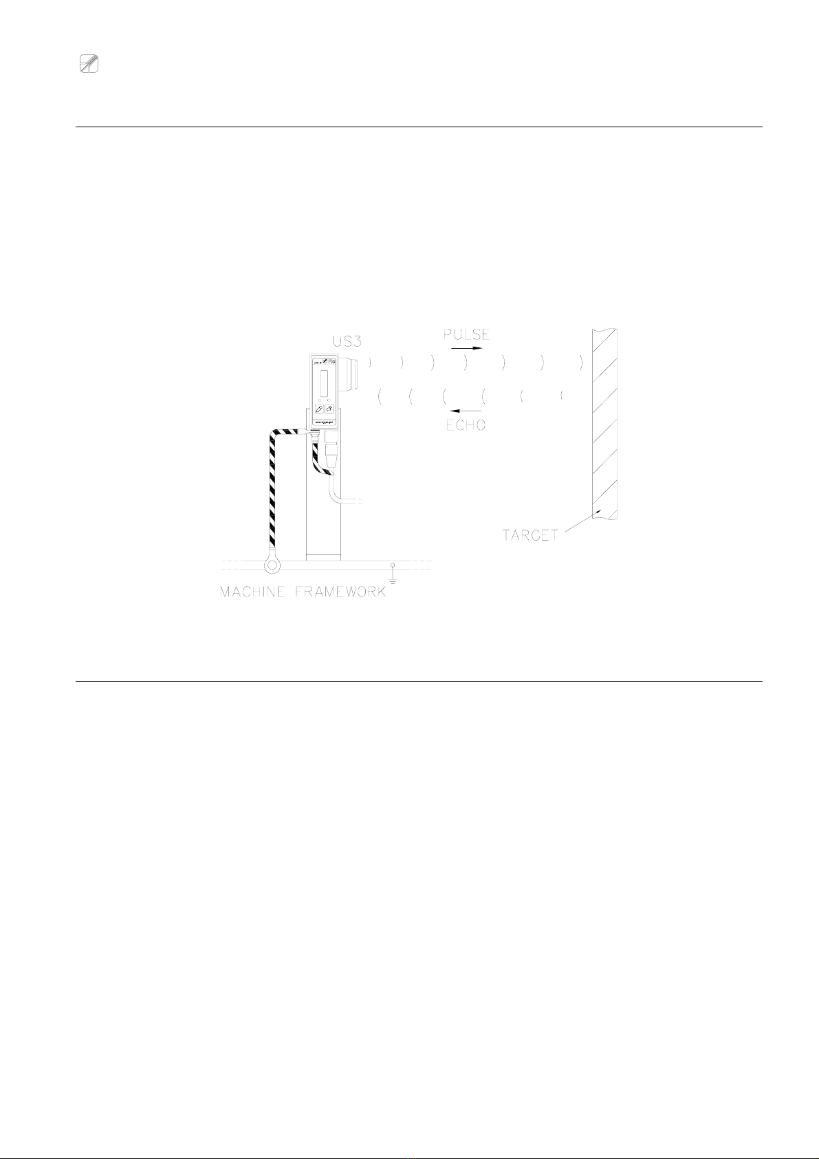
“Pulse-echo” measuring method ...................................................................................................3
Factors which influence measurement.......................................................................................... 3
Technical characteristics ................................................................................................................ 4
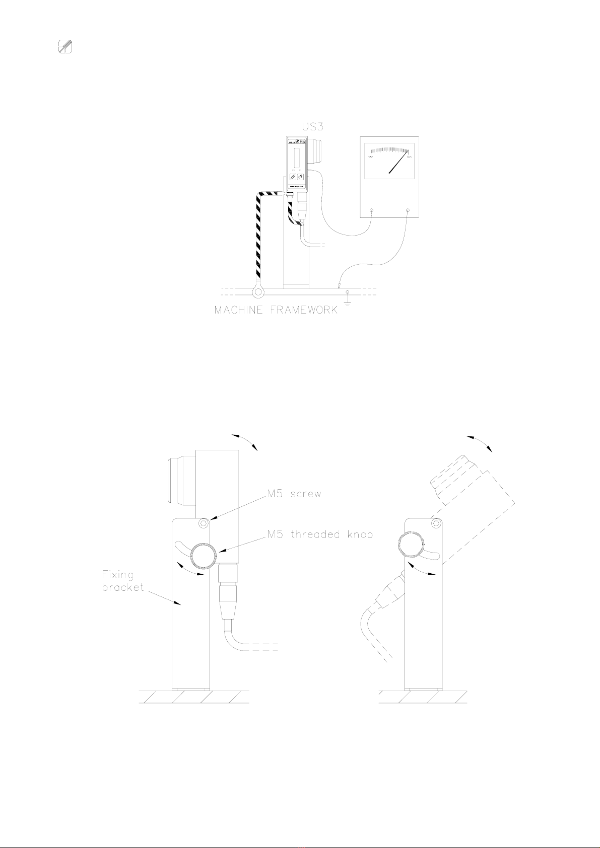
Installation ........................................................................................................................................ 4
Functioning of the device................................................................................................................ 8
General ....................................................................................................................................................8
Control panel...........................................................................................................................................8
LED bar ...............................................................................................................................................9
Status LED (green)..............................................................................................................................9
“Out of range” LED (red)......................................................................................................................9
Keys ....................................................................................................................................................9
Programming menu ....................................................................................................................... 10
Calibration....................................................................................................................................... 11
“Field” calibration by maximum and middle diameter.........................................................................12
“Lab” calibration by maximum diameter and axis...............................................................................13
Configuration of the sensor as distance reader ......................................................................... 14
Detailed description of the functions...........................................................................................15
F1 - Regulated output type selection (Volt o mA) ..............................................................................15
F2 - Minimum distance calibration (maximum diameter) ...................................................................15
F3 - Middle diameter calibration - only for field calibration................................................................16
F4 - Maximum distance calibration (axis calibration) - only for lab calibration ...................................16
F5 - Setting 1st alarm threshold..........................................................................................................17
F6 - Setting 2nd alarm threshold.........................................................................................................17
F7 - Regulated output inversion.........................................................................................................17
F8 - Led bar mode .............................................................................................................................18
F9 - Thermal probe exclusion ............................................................................................................18
F10 - Exit menu saving the data ........................................................................................................18
Reset .................................................................................................................................................18
Setpoint ........................................................................................................................................... 19
Electrical and mechanical characteristics................................................................................... 20
Mechanical dimensions................................................................................................................. 21
Electrical connection diagrams.................................................................................................... 22
Guarantee........................................................................................................................................ 23

Re S.p.A. US3
Rev.12/04/11 1/23
Warnings
The present manual is for device fitters and operators. It provides indications on the intended use of the
device, technical specifications and instructions for installation, adjustment and use.
This manual is an integral part of the device and must be kept until the device is decommissioned. It reflects
the technical state of the device at the time of its sale.
The plant builder may include the present manual in the documentation for plant use.
Re S.p.A. reserves the right to update its production and/or manuals without updating products already sold
and previous manuals.
Since the device forms part of a plant, the plant builder is responsible for ensuring that all parts comply with
the laws in force in the country in which it is installed.
The device must be fitted and adjusted by qualified technical personnel.
It may be moved manually.
Information about device recovery
- In European Union member states
The device falls within the electrical and electronic equipment category, which must be disposed of not
amongst undifferentiated urban waste, but through separate collection. Therefore, at the end of the
device’s lifetime, it must be disposed of in conformity with the European standards adopted in the
member state in which it was installed.
WEEE (Waste Electrical and Electronic Equipment) may be intended for individual, collective or mixed
collection and recovery systems at designated centres (for more information contact the relevant local
authorities) or may be returned to the distributor when a new item of equipment is purchased. This
eliminates or reduces potentially negative effects on the environment deriving from improper use of the
equipment or parts of it.
For correct waste management, the relevant authorities promote the reduction of final waste disposal by
means of re-use, recycling and other forms of recovery to obtain raw materials from waste.
In the event of illegal disposal of WEEE, offenders will be punished in accordance with the sanctions
established by the member state in which it was installed.
- In non-EU countries
Recovery and final disposal of the device must be carried out in conformity with the standards in force in
the country in which it was installed. It may be advisable to take into account the information provided
regarding European Union member states.
The device bears a clear, visible and indelible indication allowing identification of the
manufacturer and the separate collection symbol (symbol on side).
This symbol, showing a wheelie bin with a cross through it, unequivocally indicates that
the device was released after 13.08.2005 and that it must be subject to separate
collection.

Re S.p.A. US3
Rev.12/04/11 2/23
Ultrasonicsensoradvantages
Ultrasonic sensors are extremely advantageous in comparison with other sensor types:
They are able to “see” any non-sound-absorbent material and some kinds of sound-absorbent
materials.
Material colour has no effect on reading.
Target object surface has no effect on reading.
Ultrasonic sensors work in most environmental conditions (e.g. foggy, dusty, dirty, brightly lit, and
very dark).
Ultrasonic sensors are able to read transparent materials.
Ultrasonic sensors are able to ignore background disturbances.
Ultrasonicsensorlimitations
They are not suitable for detecting materials particularly good at absorbing sound.
They have a relatively low propagation speed, limiting the sensor reading speed.
They do not work in water, in high pressure or vacuum environments.
They may be affected by the presence of nearby ultrasound sources (e.g.: other ultrasonic sensors or
compressed air guns).
Typicalapplications
Laminated materials tension control.
Winding and unwinding converting industrial machinery roll diameter measurement (cutter,
rotogravure, cutting and winding machines, wrinkling machines).
Diameter roll measurement for positioning and working phase starting.
Diameter reel measurement (aluminium and sheet).
Distance measure.
Box inside liquid level measurement.
Full and empty box recognition.

Re S.p.A. US3
Rev.12/04/11 3/23
“Pulse-echo”measuringmethod
Every 100 milliseconds the US3 sensor emits an ultrasonic pulse at a frequency of 125kHz. The pulse
propagates in the air until it hits the target (positioned in front of the sensor) whose distance is to be
measured. The pulse is reflected (echo) by the object and picked up by the sensor which, based on the
time taken by the echo to return to the sensor and the sound propagation speed, calculates the distance
from the object.
After the pulse has been generated, the sensor is inhibited for a short time during which it cannot receive
the echo. This is a feature common to all “pulse-echo” sensors and defines the minimum distance which
can be measured.
Factorswhichinfluencemeasurement
Although ultrasonic sensors can operate in adverse environmental conditions, it is important to consider
several factors which affect measurement quality, so as to achieve the best possible performance:
The speed of the sound varies with the temperature, causing a measurement percentage error of
around 0.17%/°C. US3 has an internal temperature sensor which allows that error to be
compensated for automatically.
Big changes in temperature along the measuring path cannot be compensated for and may result in
sound diffraction and scattering.
Changes in atmospheric pressure do not affect measurements. We strongly advise against the use
of ultrasonic sensors in pressurised or vacuum environments, since there may be a significant
distortion in the reading.
The presence of nebulised liquids or powders in the air attenuates the sound, reducing the maximum
reading distance.
Draughts may divert the echo and prevent correct measurement.
Other ultrasound sources may overlap the echo, causing measurement errors.
Moisture may cause a temporary drop in reading sensitivity without damaging the sensor. Do not
allow ice to form on the surface of the sensor.
Small amounts of dust do not affect measurements. But it is important to keep the sensor clean. Do
not paint the surface of the ultrasonic capsule.
Clean the sensor with low pressure dry air.

Re S.p.A. US3
Rev.12/04/11 4/23
Technicalcharacteristics
Operating frequency: 125kHz
Minimum measuring distance: 150mm at 25°C (160mm at 50°C )
Maximum measuring distance: 1800mm
(for materials which absorb sound: this is reduced in proportion to
the degree to which the material absorbs sound)
Operating mode: - Diameter reader / Regulator (resolution 0.5mm)
2 analog outputs: - Proportional diametral output 0-10V
- Regulated diametral output 0-10V or 4-20mA
(possibility of inverting the regulated diametral output)
Setpoint analog input
10V reference voltage for setpoint external potentiometer connection
Software filter to prevent sudden changes in distance
2 digital outputs for alarms with programmable threshold
10-position multi-purpose LED bar
Target present indicator
Automatic compensation of change in speed of sound with temperature
RS-485 for connection to Personal Computer
Power supply: 24V dc
Installation
To ensure that the device is installed efficiently, follow the instructions below:
1. Even if the device can function properly at a voltage that varies between 18 and 30Vdc, always supply
a stabilised voltage that is not affected by network load variations.
2. Never leave a break in the cable shielding. If a connector or joint has to be inserted in the US3
cable, make the connection as shown as shown in the diagram:
3. The CLAMP ferrite provided with the equipment must be applied to the cable.

Re S.p.A. US3
Rev.12/04/11 5/23
4. Avoid using single wires connections to the US3 cable, if it is possible.
5. Below is the sensor directivity graph, with an action cone of approximately +/-10°. Install the sensor so
that inside said cone there are no: objects other than the target, other ultrasound sources, draughts.

Re S.p.A. US3
Rev.12/04/11 6/23
6. Use the metal bracket supplied to support the US3, making sure that the capsule is parallel with the
plane at a tangent to the surface to be measured. Connect the sensor body to the nearest machine
earth point with a suitable cable, as illustrated below.

Re S.p.A. US3
Rev.12/04/11 7/23
7. Be sure that between the sensor body and the machine framework there is electrical continuity
8. Adjust the sensor angle so that the target is at the centre of the action cone. Tighten the knob to secure
it.

Re S.p.A. US3
Rev.12/04/11 8/23
Functioningofthedevice
General
US3 ultrasonic sensor is suitable to read reel diameters: by a simple calibration it is able to convert a
distance measure in a reel diameter measure providing a diameter proportional analogue output.
It is equipped with an analogue setpoint input which makes US3 a strength self-governing regulation
system: you can modify material strength connecting regulated analogue output to a brake and varying the
associated tension. Material strength will not change during reel unwinding because brake command
tension will be reduced according to diameter.
US3 has a second analogue output which varies proportionally to diameter and is not influenced by setpoint
input changes, the output can be used to visualize the diameter on a display.
Two digital outputs allow the control of relays for activating alarms at diameter values which can be set by
the user.
A software filter protects the reading against big changes in distance which are not lasting, for example due
to reels having an irregular shape.
US3 can also function as a distance reader just by using the regulated output inversion.
The RS-485 serial port allows rapid sensor configuration using a Personal Computer (with integrated RS-
485 port or RS-232/RS-485 external converter) and special “US Calibration” software can be downloaded
free of charge from the website www.re-spa.com.
Control panel
LED BAR: for displaying information
about the measurement and facilitating
navigation in the programming menu
LEDs providing useful information about
the instrument status
KEYS for accessing programming
functions

Re S.p.A. US3
Rev.12/04/11 9/23
LED bar
During programming: shows the number of the function selected, with the corresponding LED lit (the first
from the bottom for F1, the second for F2, etc.).
Outside programming: indicates the level of the proportional or regulated output depending on the mode set
in function F8.
Status LED (green)
During programming: remains lit
Outside programming: flashes.
“Out of range” LED (red)
During programming: for the meaning of this LED during programming, see the detailed description of the
functions.
Outside programming: the LED begins flashing quickly if the target moves out of the reading range allowed
or cannot be detected by the sensor because it is not there.
Keys
Note: Press ENTER+SET for several seconds outside the programming environment to reset the
device, restoring the factory settings.
ENTER
Outside programming: if pressed for several seconds allows programming to be accessed.
During programming:
for going to the next function;
if pressed with the SET key in function F10, returns you to function F1;
if pressed for several seconds in function F10, allows you to exit programming and save
the settings;
if pressed while field calibration is active, allows output increase/reduction.
SET
Outside programming: interrupts LED bar flashing if there was an error saving the settings.
During programming:
for inverting the value set for functions F1, F7, F8 and F9;
for calibrating the parameters in functions F2, F4, F5, F6 and in field calibration;
if pressed with the ENTER key in function F10, returns you to function F1.

Re S.p.A. US3
Rev.12/04/11 10/23
Programmingmenu
Below is a list summarising the device programming functions available. For more details, see from page
15.
To access programming press ENTER for several seconds, the green LED remains lit and the first LED on
the LED bar lights up (function F1).
To scroll through the menu of the programming functions, use the ENTER key.
To return to function F1 go to function F10 and press ENTER+SET.
To exit programming go to function F10 and hold down ENTER for several seconds. If the parameters were
saved correctly, the LED bar lights scroll, otherwise it begins flashing until you press SET.
Function
number
Bar
position Description Keys Value range
Factory
setting
F1 1 Regulated output type selection SET 0→1 0
F2 2 Minimum distance calibration SET 150mm→D.max -1 150mm
F3
3
Middle diameter calibration
See detailed description of field calibration
(page 16)
F4 4 Maximum distance calibration SET D.min.+1→1800mm 1800mm
F5 5 Setting 1st alarm threshold SET 150mm→1800mm 1600mm
F6 6 Setting 2nd alarm threshold SET 150mm→1800mm 1700mm
F7 7 Regulated output inversion SET 0→1 0
F8 8 Led bar mode SET 0→1 0
F9 9 Thermal probe exclusion SET 0→1 1
F10 10 Exit menu saving the data ENTER - -

Re S.p.A. US3
Rev.12/04/11 11/23
Calibration
To operate as diameter reader / regulator, the US3 ultrasonic sensor must be calibrated.
By measuring the distance from the reel, the sensor can measure the reel diameter. In particular, when the
reel diameter is at its maximum size the sensor reads the minimum distance. As the diameter is reduced,
the distanced measured increases, until the maximum distance corresponding to the minimum diameter
(see images below).

Re S.p.A. US3
Rev.12/04/11 12/23
“Field” calibration by maximum and middle diameter
Where must be done
It is a field calibration. Sensor is mechanically installed in its own definitive position.
How calibrate
Enter the programming menu (see on page 10);
Press ENTER to position on function F2;
Carry out function F2 for field calibration as described on page 15;
Position on function F3 and carry out as described on page 16.
Position on function F10 and keep pressed ENTER key to save and exit.
Advantages
Allows you to set the precise value the output adopts at the intermediate diameter.
Disadvantages
It is necessary to use a voltmeter.
It is necessary to know maximum and middle diameter.

Re S.p.A. US3
Rev.12/04/11 13/23
“Lab” calibration by maximum diameter and axis
Where must be done
The calibration is carried out on lab table before sensor has been mechanically installed in its own
position.
How calibrate
Enter the programming menu (see on page 10);
Press ENTER to position on function F2;
Carry out function F2 for lab calibration as described on page 15;
Position on function F4 and carry out as described on page 16.
Position on function F10 and keep pressed ENTER key to save and exit.
Advantages
It allows to easily calibrate the device in a completely digital way.
It is not necessary any measurement instrument.
When you order the device if you know the distances between sensor (capsule surface) and
maximum diameter reel and between regulator and rotation axis, US3 could be sold already
calibrated for the specific application.
Disadvantages
You must pay attention to position the stiff target (ex. cardboard) as more parallel as possible to the
capsule plane.
It is necessary to know the distances between sensor (capsule plane) and maximum diameter and
between regulator and rotation axis.
Attention: the procedure described above could be carried out when sensor has been already
mechanically installed in its own definitive position, using two targets, one corresponding to
maximum diameter (F2) the other one to rotation axis (F4).

Re S.p.A. US3
Rev.12/04/11 14/23
Configurationofthesensorasdistancereader
To use the sensor as distance reader you have to:
enter the programming menu (see on page 10);
press ENTER to position on function F7;
the red LED shows the current value of the function:
-if the red LED is lit the inversion is already enabled,
-if the red LED is off the inversion is disabled: press SET key to enable the inversion;
position on function F10 and keep pressed ENTER key to save and exit.
short-circuit the green and brown wires (as shown in the diagram on page 22, Configuration without
setpoint potentiometer section)
In this way the 0V regulated output corresponds to the minimum distance, instead the 10V regulated output
corresponds to the maximum distance.

Re S.p.A. US3
Rev.12/04/11 15/23
Detaileddescriptionofthefunctions
Outside programming, the green LED flashes to indicate that the device is operating normally. To access
the programming menu, hold down ENTER for several seconds. The green LED will stop flashing and
remain lit together with the LED on the LED bar corresponding to function F1.
Nominal values are:
Regulated diametrical output: set on Volt
Distance from the axis: 1,8 meters
Distance from the maximum diameter: 15 cm
1st alarm distance: 1,6 meters
2nd alarm distance: 1,7 meters
Inversion of the regulated diametrical output: disabled
Led bar: set to display the level of the proportional diametrical
output
Instrument serial identification: 0 (changeable only using Personal Computer).
See Calibration section to carry out the first calibration after sensor purchase.
F1 - Regulated output type selection (Volt o mA)
The red LED shows the current value of the function:
-if the red LED is lit the type of output is mA
-if the red LED is off the type of output is Volts
Press SET key to set the desired value.
To select following function press ENTER key.
F2 - Minimum distance calibration (maximum diameter)
Important: Before calibrating, make sure that there are no objects other than the target in the
sensor’s action cone.
Lab calibration (sensor not installed in its own working position): position a stiff target (ex.
cardboard) in front of the sensor. The distance between target and the capsule has to be the same
one which is between sensor and maximum diameter reel once sensor is installed in its own working
position (see diagram on page 13).
Field calibration (sensor installed in its own working place): position maximum diameter reel in front
of the sensor (see diagram on page 12).
The red LED indicates the presence of the target:
-if the red LED is off the target is present and calibration can be performed correctly
-if the red LED is flashing the target is not detected and calibration is impossible
To calibrate, make sure that the red LED remains constantly off then press SET; if calibration has
been performed the red LED flashes twice.
To select following function press ENTER key.

Re S.p.A. US3
Rev.12/04/11 16/23
F3 - Middle diameter calibration - only for field calibration
Important: Before calibrating, make sure that there are no objects other than the target in the
sensor’s action cone.
Position a known diameter reel in front off the sensor (diagram on page 12).
The red LED indicates the presence of the target:
-if the red LED is off the target is present and calibration can be performed correctly
-if the red LED is flashing the target is not detected and calibration is impossible
Connect a voltmeter to one of the sensor’s two analog outputs (blue wire or orange wire).
To start calibration make sure that the red LED remains constantly off then press SET; the red LED
will light up and the output voltage will increase starting from 5V.
Use the ENTER key to increase or reduce the voltage. When the output reaches the value calculated
using the formula shown below, press SET to confirm it. If calibration has been performed the red
LED flashes twice.
[
]
(
)
[]
mmdiametermaximum
mmdiameterknown*10
volt =
Es. If maximum diameter is 1000 mm and known diameter is 400 mm, output must be 4Vdc.
(
)
4
1000
400*10
volt ==
To select following function press ENTER key.
F4 - Maximum distance calibration (axis calibration) - only for lab calibration
Important: Before calibrating, make sure that there are no objects other than the target in the
sensor’s action cone.
Position a stiff target (ex. cardboard) in front of the sensor. The distance between target and the
capsule has to be the same one which is between sensor and the reel rotation axis once sensor is
installed in its own working position (see diagram on page 13).
The red LED indicates the presence of the target:
-if the red LED is off the target is present and calibration can be performed correctly
-if the red LED is flashing the target is not detected and calibration is impossible
To calibrate, make sure that the red LED remains constantly off then press SET; if calibration has
been performed the red LED flashes twice.
Note: rotation axis is the centre of reel shaft.
To select following function press ENTER key.

Re S.p.A. US3
Rev.12/04/11 17/23
F5 - Setting 1st alarm threshold
Important: Before calibrating, make sure that there are no objects other than the target in the
sensor’s action cone.
This function allows you to set a threshold diameter below which the sensor activates the first of the two
alarm outputs. The output will remain activated until the diameter returns above the threshold value plus
5mm, to prevent sudden activations when the diameter is close to the threshold value.
Place a reel with diameter equal to the threshold diameter in front of the sensor (or an obstacle at a
distance equal to that which would separate the capsule from the reel with the threshold diameter).
The red LED indicates the presence of the target:
-if the red LED is off the target is present and calibration can be performed correctly
-if the red LED is flashing the target is not detected and calibration is impossible
To calibrate, make sure that the red LED remains constantly off then press SET; if calibration has
been performed the red LED flashes twice.
To select following function press ENTER key.
F6 - Setting 2nd alarm threshold
Important: Before calibrating, make sure that there are no objects other than the target in the
sensor’s action cone.
This function allows you to set a second threshold diameter below which the sensor activates the second of
the two alarm outputs. The output will remain activated until the diameter returns above the threshold value
plus 5mm, to prevent sudden activations when the diameter is close to the threshold value.
Place a reel with diameter equal to the threshold diameter in front of the sensor (or an obstacle at a
distance equal to that which would separate the capsule from the reel with the threshold diameter).
The red LED indicates the presence of the target:
-if the red LED is off the target is present and calibration can be performed correctly
-if the red LED is flashing the target is not detected and calibration is impossible
To calibrate, make sure that the red LED remains constantly off then press SET; if calibration has
been performed the red LED flashes twice.
To select following function press ENTER key.
F7 - Regulated output inversion
The red LED shows the current value of the function:
-if the red LED is lit the inversion is enabled (the maximum output corresponds to the minimum
diameter and the minimum output to the maximum diameter)
-if the red LED is off the inversion is disabled (the maximum output corresponds to the maximum
diameter and the minimum output to the minimum diameter)
Press SET key to set the desired value.
To select following function press ENTER key.
Table of contents
Other Re Accessories manuals
Popular Accessories manuals by other brands

Stulz Tecnivel
Stulz Tecnivel EV installation guide

Gardner Denver
Gardner Denver THOMAS SK61732 manual

Panasonic
Panasonic PE Series instruction manual

Swann
Swann SR16220 Installation and user guide

Safety Technology International
Safety Technology International STI-WS103 Installation and operating instructions

Giropes
Giropes GI400i user manual

Yeelight
Yeelight YLYD01YL user manual

V-TAC
V-TAC VT-3508 manual

Johnson Hardware
Johnson Hardware 100FD 100FD Series installation instructions

ROSE DISPLAYS
ROSE DISPLAYS ANOGOTCHA PLUS WITH MULTICLIPS manual

Creative Play
Creative Play T119 installation instructions

Frigidaire
Frigidaire FEC450WH00 use & care