Real Carriage Door & Sliding Hardware Frankling Autoswing User manual

INSTALLATION MANUAL

CAUTION!
It is recommended that you have a low voltage electrician, or trade member
familiar with gate installations to install the operator. You may call us or the
manufacturer to see if there is anyone in your area familiar with the Franklin
Autoswing. Real Carriage Door & Sliding Hardware is not liable for any
damage that occurs during install, and replacements are the sole
responsibility of the installer and customer. The manufacturer does carry a
warranty for any defects or issues that are from manufacturing only and will
have to be tested by the manufacturer’s technical team before sending
replacements.
It is also a good idea to install a surge protector to avoid any damage to the
operator. The operator can be damaged by power surges or faulty wiring.

Thank you for buying this product, our company is sure that you will be more than satised with
the product’s performance. The product is supplied with a “Warnings” leaet and an “Instruc-
tion booklet”. These should both be read carefully as they provide important information about
safety, installation, operation and maintenance. This product complies with the recognized
technical standards and safety regulations.
1) GENERAL OUTLINE
The control panel is supplied by the manufacturer with standard settings. Any alteration must be
set by means of the incorporated display programmer or by means of UNIPRO. The Control unit
completely supports the EELINK protocol. Its main characteristics are:
- Control of two low-voltage motors up to 40W power
- Electronic torque setting with obstacle detection
- Limit-switch control inputs
- Separate inputs for safety devices
- Incorporated rolling-code radio receiver with transmitter cloning
- Soft start and close
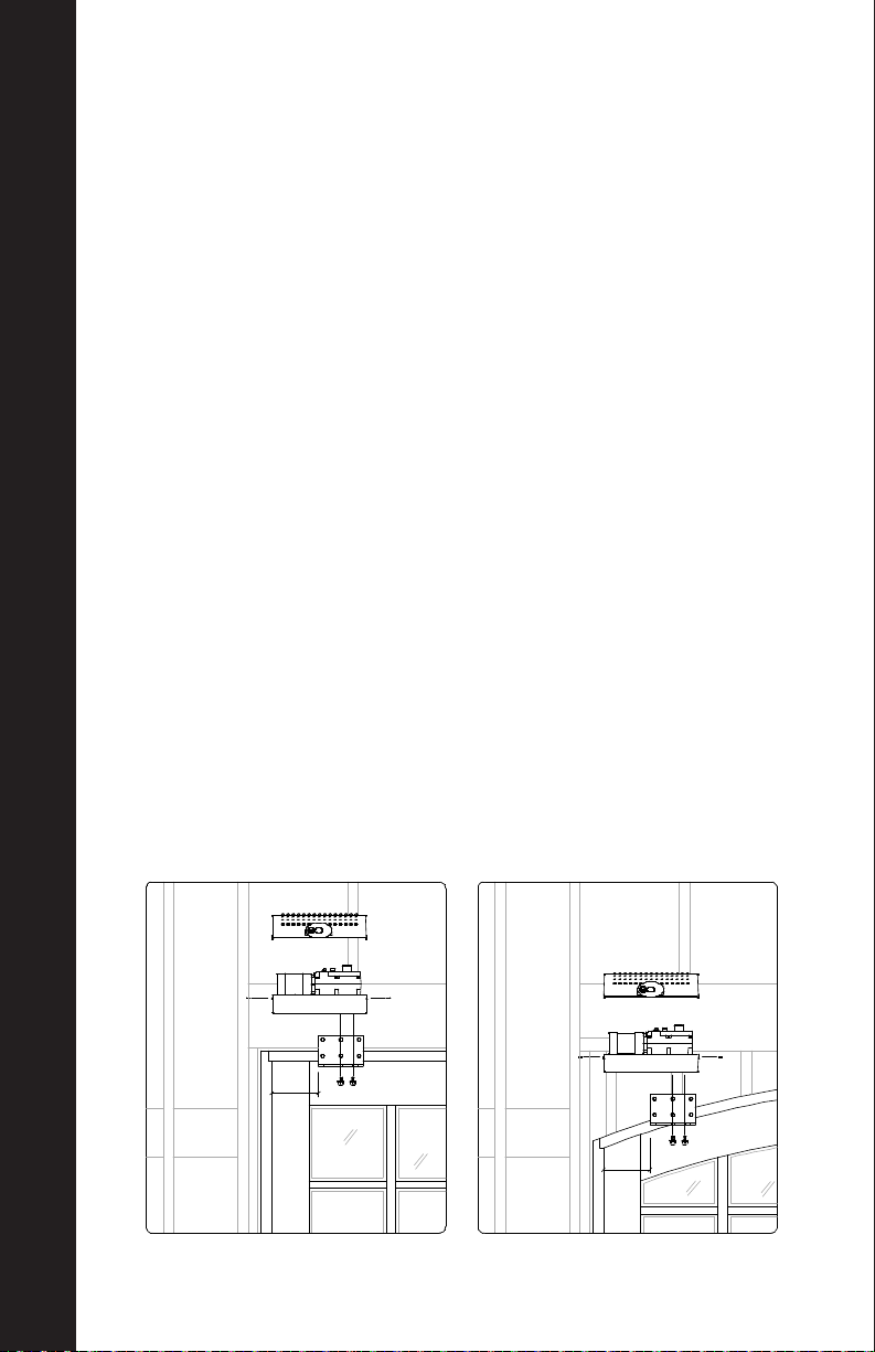
The IGEA-BT (24V) is suitable for residential use and has been designed for swing gates with
particularly large gate posts. The drive arm, built with a special anti-shearing shape, allows the
leaves to be moved when the controller is considerably out of place with respect to the fulcrum of
the leaves. The non-reversible electro-mechanical motor maintains the stop during closing and
opening. The release knob with personalized key, tted outside each operator, makes manual
operation extremely easy.
2) SAFET Y
If correctly installed and used, this automation device satises the required safety level stan-
dards. However, it is advisable to observe some practical rules in order to avoid accidental
problems. Before using the automation device, carefully read the operation instructions and
keep them for future reference.
• Keep children, persons and things outside the automation working area, particularly during op-
eration. An incorrect installation or improper use of the product can cause damage to persons,
animals or things.
• Keep radio control or other control devices out of children’s reach, in order to
avoid any unintentional automation activation.
• Do not intentionally oppose the leaf movement.
• BFT and Real Carriage Door & Sliding Hardware declines all responsibility for any consequenc-
es resulting from failure to observe Good Technical Practice when constructing closing structures
(door, gates etc.), as well as from any deformation which might occur during use.
• The installation must comply with the provisions set out by the following directives: 89/336/CEE,
73/23/EEC, 98/37/EEC and subsequent amendments.
• Do not attempt to open the gate by hand, if the actuator has not been released by means of
the appropriate release knob.
• Do not modify the automation components.
• In case of malfunction, disconnect the power supply, activate the emergency release to gain
access to the actuator and request the assistance of a qualied technician (installer).
• Before proceeding to any external cleaning operation, disconnect the main powers supply and
at least one of the battery pole, if tted.
• Check that grounding is carried out correctly: connect all metal parts for closure (doors, gates
etc.) and all system components provided with an earth terminal.

• Fit all the safety devices (photocells, electric edges etc.) which are needed to protect the area
from any danger caused by squashing, conveying and shearing, according to and in compliance
with the applicable directives and technical standards.
• Keep the photocell optical components and luminous signal indication devices clean. Check
that the photocells are not obscured by branches or shrubs.
• For any direct assistance to the automation system, request the assistance of a qualied
technician (installer).
• Have qualied personnel check the automation system once a year.
• Entrance is reserved for vehicles, provide a separate entrance for pedestrians.
3) SCRAPPING
Warning: This operation should only be carried out by qualied personnel. Materials must be dis-
posed of in conformity with the current regulations. In case of scrapping, the automation devices
do not entail any particular risks or danger. In case of materials to be recycled, these should be
sorted out by type (electrical components, copper, aluminum, plastic etc.).
4) DISMANTLING
Warning: This operation should only be carried out by qualied personnel. When the control unit
is disassembled to be reassembled on another site, proceed as follows:
• Disconnect the power supply and the entire electrical installation.
• In the case where some of the components cannot be removed or are damaged, they must be
replaced.
5) FUNCTIONS
FOR THE INSTALLER: Fill in the table with the parameters set, in order to facilitate future modi-
cations and maintenance operations. The preset values are indicated between square brackets
[ ].
WARNINGS
Correct controller operation is only ensured when the data contained in the present manual are
observed. The company is not to be held responsible for any damage resulting from failure to
observe the installation standards and the instructions contained in the present manual.
The descriptions and illustrations contained in the present manual are not binding. The Company
reserves the right to make any alterations deemed appropriate for the technical, manufactur-
ing and commercial improvement of the product, while leaving the essential product features
unchanged, at any time and without undertaking to update the present publication.
ATTENTION! The IGEA-BT model controller is not equipped with mechanical torque adjustment.
It is compulsory to use a control panel of the same manufacturer, in compliance with the basic
safety requirements of directives 73/23/CEE, 89/336/CEE, 89/37/CEE equipped with appropriate
electric adjustment of the torque.
Correct controller operation is only ensured when the data contained in the present manual are
observed. The company is not to be held responsible for any damage resulting from failure to
observe the installation standards and the instructions contained in the present manual.
The descriptions and illustrations contained in the present manual are not binding. The Company
reserves the right to make any alterations deemed appropriate for the technical, manufactur-
ing and commercial improvement of the product, while leaving the essential product features
unchanged, at any time and without undertaking to update the present publication.

CHAPTERS
TABLE OF CONTENTS
The table of contents are listed to assist you locating a desired section. We
do however strongly suggest reading the entire instruction manual before
attempting installation. Note that this manual is for outswing garage
doors. IMPORTANT! This installation manual is designed as a supplement
to the BFT product manuals. Be sure to read the safety information in all
product literature associated with this opener system, as well as comply
with all of the specications they contain.
For all programming parameters, please refer to the Thalia UL Control Panel from BFT.
1
2
3-4
5
6
7-8
9
10-11
12-14
15 -18
19-20
21
22
23-24
25-27
28
29
30-34
TABLE OF CONTENTS
APPENDICES
Specications
System Overview
Motor Installation
Limit Switch Installation
Manual Operation Mode
Mounting the Control Unit
Installing Motor Cover
Wiring Simplied
Autoset Programming
Programming Features
Installing Wired Wall Button
Accessories
Programming Additional Remotes
Homelink
Outdoor Keypad
Wireless Wall Button
Battery Backup
Wi- Hub
Programming Menu
Arched Door Applications
Homelink Troubleshooting
Error01 code Troubleshooting
35-37
38-39
40-47
48-49

Mounting Clearance 7.5” Above Lowest Part of Door
Jamb
Voltage 24 V
Power Supply 120 V 60 Hz Single-Phase
Absorbed Power 0.05 hp (40 W)
Opening or Closing Time 15 s
Impact Reaction Torque Limiter on Control Panel
Manual Release Release Knob with Personalized Key
Operating Cycle Intensive Use
Environmental Conditions 5°F - 140°F
Degree of Protection IP44
Operator Weight 35 lbs
Door Leaf Max Length Up to 10 ft
Door Leaf Max Surface
Area 120 ft2
Maximum Open Angle Up to 125°
Weight Limit 550 lbs
1 SPECIFICATIONS
SPECIFICATIONS

SYSTEM OVERVIEW
Below is an example of typical component placement and wiring. Please
note that the Control Housing must have holes drilled into it to run the
wires. UL Listed stress-relief connectors are recommended. Be careful
not to damage the panel when drilling into the housing! It is a good idea
to remove the panel while drilling. Refer to “Wiring Simplied” for more
detailed views of Control Panel connections. Surge protection and a
dedicated circuit are encouraged.
TypicalSystemOverview
Belowisanexampleoftypicalcomponentplacementandwiring.PleasenotethattheControlHousing
musthaveholesdrilledintoittorunthewires.ULListedstress‐reliefconnectorsarerecommended.Be
careful not to damage the panel when drilling into the housing! It is a good idea to remove the panel
while drilling. Referto“MasterWiringDiagram”formoredetailedviewsofControlPanelconnec�ons.
Surgeprotec�onandadedicatedcircuitareencouraged.
*Motors are low voltage. Use braided wire.
Increase wire gauge if motors mounted
more than 20’ from control housing.
**From lowest part of jamb to ceiling line.
A. Control Housing (dims 7.25” x 8.75” x 3.5”)
B. Left Motor
C. Right Motor
D. Receiver Photoeye
E. Transmitter Photoeye
F. Wall Pushbutton
G. 2-Button Remote Transmitter (2)
H. Antenna (for extra range applications)
TM
Franklin Autoswing Installation Manual
© 2012 Copyright Real Carriage Door Company, Inc
7
A. Control Housing (dims. 9.5” x 11.5” x 5.75”)
B. Left Motor
C. Right Motor
D. Receiver Photoeye
E. Transmitter Photoeye
F. Wall Pushbutton
G. 4-button Remote Transmitter (2)
H. Extended Range Antenna (optional)
*Motors are low voltage. Use Stranded wire.
Increase wire gauge if motors mounted more
than 20’ from control housing.
** From lowest part of jamb to sealing
16ga/3*
22ga/5
16ga/3*
16ga/3*
2 SYSTEM OVERVIEW

MOTOR INSTALLATION
TIP: Before mounting, refer to “Typical System Overview” for prewiring. For a
very ‘clean’ installation, mount the unit directly on the head casing (if at pro-
le). Note that this motor positioning is for outswing doors only.
1.Removethecovertothemotorandsetaside.
2.Removethemotorfromthebaseplatebylooseningthe4boltsontheboomofthemotor.
3.Posionthebaseplate(notethatbodyofthemotorshouldextendtowardthesidejamb)about7”fromtheedge
ofthedoor*.Leveltheplateandmarkthelocaonsoftheholes.TIP:Formostapplicaons,centeringtheboom
rowofholesonthejambmakesforthemostsecureinstallaon.
Lebaseplateposion,squaretop
door(interiorview)
Installa�onofMotor
TIP:Beforemounng,referto“TypicalSystemOverview”forprewiring.Foravery‘clean’
installaon,mounttheunitdirectlyontheheadcasing(ifatprole).Notethatthismotor
posioningisforoutswing doors only.
4.Levelandmounttheplatewithminimum3/8”x4”lagbolts(notsupplied).Forproperarmclearance,theboom
oftheplatemustnohigherthanthelowestpartofthejamb.Alwaysmakecertainthatthelagboltspenetratesolid
headerand/orblockingmaterial.
5.Reaachthemotortothebaseplateandghtensecurely.Besurethatthemotorisseatedproperlyinitsplasc
housing.
*NOTE: There are limita�ons for certain arch‐top radii rela�ve to the door width. See table in
APPENDIX C for allowable radii, and APPENDIX D for more help in posi�oning.
Lebaseplateposion,archtop
door(interiorview)
7”
7”
Franklin Autoswing Installation Manual
TM
8
© 2012 Copyright Real Carriage Door Company, Inc
1. Remove the cover to the motor and set aside.
2. Remove the motor from the base plate by loosening the 4 bolts on the
bottom of the motor.
3. Position the base plate (note that body of the motor should extend toward
the side jamb) about 7” from the edge of the door*. Level the plate and mark
the locations of the holes. TIP: For most applications, centering the bottom
row of holes on the jamb makes for the most secure installation.
*NOTE: There are limitations for certain arch-top radii relative to the door
width. See table in APPENDIX C for allowable radii, and APPENDIX D for more
help in positioning.
4. Level and mount the plate with minimum 3/8” x 4” lag bolts (not supplied).
For proper arm clearance, the bottom of the plate must no higher than the
lowest part of the jamb. Always make certain that the lag bolts penetrate
solid header and/or blocking material.
5. Re-attach the motor to the base plate and tighten securely. Be sure that
the motor is seated properly in its plastic housing.
6. Assemble the articulated lever arm and door coupling as shown in g. 1.
Connect straight arm and door coupling to curved arm using plastic sleeve
(K) and washer (L). Secure together with rolled pin (M). The dashed arm indi-
cates the setup for the right motor (viewed from inside).
7. Slide the assembled arm onto the transmission shaft at the base of the
motor, and fasten it using the long pin (N) and C-ring (O).
3 MOTOR INSTALLATION

1.LocatethecontrolhousingcontainingtheLIBRAULRpanel.
2.Formounng,therearofthehousingmustbepredrilled.Refer
tog.5forthelocaonsoftheholestobedrilled.
3.Atthisme,planwhereyouwouldliketorunthewiringinto
thehousingandpredrillforstressreliefconnectors.Be careful
not to damage the panel when drilling into the housing! It is a
good idea to remove the panel while drilling.
4.Mountthehousingsecurely,usingeitherscrewsordrywall
anchors(notsupplied).Becarefulnottodamageanywiresor
componentsoftheboard.(See“TypicalSystemOverview”for
suggestedlocaonofthehousing)
Moun�ngtheControlHousing
Fig5.Mounnglocaons
Fig6.Stressreliefconnector
1.Locatethestressrelievingcordgrip.
2.Aachconnecngnut(F)togripbody(G).Tightensecurely
usingngerpressureonly.
3.Slipcompressionnut(H)overalengthof18/3(18Gauge,
3strand)motorwireandthreadwirethroughthe
assembledcordgrip.
4.Tightenthecompressionnut(H)withngerpressureonly.
5.Referto“MasterWiringDiagram”towirethemotortothe
LIBRAULRcontrolpanel.
6.Forbasicprogrammingsee“GeneralProgramming.”For
advancedparameters,pleaseseetheBFT“LIBRA‐UL‐R
Installa�on and User’s Manual”
WiringtheMotor
F
G
H
WIRE USE
min18/3wire*connecngmotorstocontrolpanel
min22/4wireconnecngRXphotoeyetocontrolpanel
min22/2wireconnecngTXphotoeyetocontrolpanel
*Use stranded wire. Increase gauge if motors more than 20’ from panel
TM
Franklin Autoswing Installation Manual
© 2012 Copyright Real Carriage Door Company, Inc
11
8. Manually release the operator (See “Manual Operation Mode”)
9. Open the door to the desired ‘fully open’ point (approx 105 degrees is
recommended). With a measuring tape, mark the centerline of the door
mounting bracket at 40” from the center of the shaft (g. 2). Making sure that
the arm is level, Mount the arm to the door with #14 x 1-1/2” pan head screws
(not supplied)
10. Check clearance and movement by swinging door slowly.
11. Relock the motor (take out of manual release mode).
12. Repeat these steps for the other leaf, if installed.
6.Assemblethearculatedleverarmanddoorcouplingasshowning.1.Connectstraightarmanddoorcouplingto
curvedarmusingplascsleeve(K)andwasher(L).Securetogetherwithrolledpin(M).Thedashedarmindicates
thesetupfortherightmotor(viewedfrominside).
7.Slidetheassembledarmontothetransmissionshaatthebaseofthemotor,andfastenitusingthelongpin(N)
andCring(O).
8.Manuallyreleasetheoperator(See“ManualOperaonMode”).
9.Openthedoortothedesired‘fullyopen’point(approx105degreesisrecommended).Withameasuringtape,
markthecenterlineofthedoormounngbracketat40”fromthecenterofthesha(g.2).Makingsurethatthe
armislevel,Mountthearmtothedoorwith#14x11/2”panheadscrews(notsupplied)
10.Checkclearanceandmovementbyswingingdoorslowly.
11.Relockthemotor(takeoutofmanualreleasemode).
12.Repeatthesestepsfortheotherleaf,ifinstalled.
Installa�onofMotor(Con�nued)
Fig1.ArmAssemblyFig2.Armposioning
K
L
M
N
O
NOTE:
1.5” is minimum allowable arm
bend. Distances over 1.5” are
acceptable.
TM
Franklin Autoswing Installation Manual
© 2012 Copyright Real Carriage Door Company, Inc
9
WIRING THE MOTOR
1. Locate the stress relieving cord-grip.
2. Attach connecting nut (F) to grip
body (G). Tighten securely using nger
pressure only.
3. Slip compression nut (H) over a
length of 16/3 (16 Gauge, 3 strand)
motor wire and thread wire through
the assembled cord-grip.
4. Tighten the compression nut (H) with
nger pressure only.
5. Refer to “Master Wiring Diagram”
to wire the motor to the LIBRA-UL-R
control panel.
6. For basic programming see “Gen-
eral Programming.” For advanced
parameters, please see the BFT
“LIBRA-UL-R Installation and User’s
Manual”
4 MOTOR INSTALLATION

1. Install the limit-switch reference cams as shown in g. 3. Install the full
cam on top of the metal shaft, then install the ring cam on top of the full
cam. Do not fully tighten the xing screws.
2. When the door is fully open, rotate the corresponding cam (g. 4), until
you hear a ‘click’ indicating the limit switch has been depressed, then lock
it in position by tightening the appropriate screws. Repeat for the fully
closed position. Refer to “Manual Operation Mode” to manually swing the
door.
3. Swing the door slowly to its open and close positions, listening to see
that the ‘click’ of the limits switch occurs where desired. Note that the left
motor’s cams (close vs open) are inverted from those of the right motor.
Adjust as necessary.
INSTALLING LIMIT SWITCHES
Installa�onofLimitSwitches
1.Installthelimitswitchreferncecamsas
showning.3.Installthefullcamontopof
themetalsha,theninstalltheringcamon
topofthefullcam.Donotfullyghtenthe
xingscrews.
2.Whenthedoorisfullyopen,rotatethe
correspondingcam(g.4),unlyouheara
‘click’indicangthelimitswitchhasbeen
depressed,thenlockitinposionby
ghteningtheappropriatescrews.Repeatfor
thefullyclosedposion.Referto“Manual
OperaonMode”tomanuallyswingthedoor.
3.Swingthedoorslowlytoitsopenandclose
posions,listeningtoseethatthe‘click’of
thelimitsswitchoccurswheredesired.Adjust
asnecessary.
Fig4.LimitSwitchfuncons
LEFTMOTOR
(viewedfrominside)
RIGHTMOTOR
(viewedfrominside)
CLOSELIMITCAM
OPENLIMITCAM
CLOSELIMIT
SWITCH
OPENLIMIT
SWITCH
OPENLIMITCAM
CLOSELIMITCAM
OPENLIMIT
SWITCH
CLOSELIMIT
SWITCH
Fig3.LimitSwitchinstallaon
FULLCAMRINGCAM
Franklin Autoswing Installation Manual
TM
10
© 2012 Copyright Real Carriage Door Company, Inc
Installa�onofLimitSwitches
1.Installthelimitswitchreferncecamsas
showning.3.Installthefullcamontopof
themetalsha,theninstalltheringcamon
topofthefullcam.Donotfullyghtenthe
xingscrews.
2.Whenthedoorisfullyopen,rotatethe
correspondingcam(g.4),unlyouheara
‘click’indicangthelimitswitchhasbeen
depressed,thenlockitinposionby
ghteningtheappropriatescrews.Repeatfor
thefullyclosedposion.Referto“Manual
OperaonMode”tomanuallyswingthedoor.
3.Swingthedoorslowlytoitsopenandclose
posions,listeningtoseethatthe‘click’of
thelimitsswitchoccurswheredesired.Adjust
asnecessary.
Fig4.LimitSwitchfuncons
LEFTMOTOR
(viewedfrominside)
RIGHTMOTOR
(viewedfrominside)
CLOSELIMITCAM
OPENLIMITCAM
CLOSELIMIT
SWITCH
OPENLIMIT
SWITCH
OPENLIMITCAM
CLOSELIMIT
CAM
OPENLIMIT
SWITCH
CLOSELIMIT
SWITCH
Fig3.LimitSwitchinstallaon
FULLCAMRINGCAM
Franklin Autoswing Installation Manual
TM
10
© 2012 Copyright Real Carriage Door Company, Inc
FIGURE 3. LIMIT SWITCH INSTALLATION
FIGURE 4. LIMIT SWITCH FUNCTIONS
5 LIMIT SWITCH INSTALLATION

ManualOperaonMode
NOTE:Whenworkingwithlimitswitches,the
keycannotbeusedtomanuallyreleasemotor.
Torelease,iptheblacklever(picturedat
right)andswingthedoor.Thelevermustbe
helddownwhileswingingasitisspringloaded.
RightMotorLeMotor
Inside
Outside
ForLEFTmotor(asviewedfrominside):
1.Turnkeyclockwise
2.Turnreleaseknobcounter‐clockwise
3.Turnkeybacktokeepinreleaseposi�on
4.Push/pulldoorslowlytoopenorclose
5.Reversestepstore‐ac�vateauto‐mode
ForRIGHTmotor(asviewedfrominside):
1.Turnkeyclockwise
2.Turnreleaseknobclockwise
3.Turnkeybacktokeepinreleaseposi�on
4.Push/pulldoorslowlytoopenorclose
5.Reversestepstore‐ac�vateauto‐mode
Inthecaseofpowerfailureoroperatormalfunc�on,manualopera�onmodecanbecarriedout
byturningtheexternalreleaseknobwithpersonalizedkey.
Franklin Autoswing Installation Manual
TM
6
© 2012 Copyright Real Carriage Door Company, Inc
FOR LEFT MOTOR
MANUAL OPERATION MODE
In the case of power failure or operator malfunction, manual operation
mode can be carried out by turning the external release knob with a
personalized key.
(As viewed from inside)
1. Turn key clockwise
2. Turn release knob counter-clockwise
3. Turn key back to keep in release position
4. Push/pull door slowly to open or close
5. Reverse steps to re-activate auto-mode
ManualOperaonMode
NOTE:Whenworkingwithlimitswitches,the
keycannotbeusedtomanuallyreleasemotor.
Torelease,iptheblacklever(picturedat
right)andswingthedoor.Thelevermustbe
helddownwhileswingingasitisspringloaded.
RightMotorLeMotor
Inside
Outside
ForLEFTmotor(asviewedfrominside):
1.Turnkeyclockwise
2.Turnreleaseknobcounter‐clockwise
3.Turnkeybacktokeepinreleaseposi�on
4.Push/pulldoorslowlytoopenorclose
5.Reversestepstore‐ac�vateauto‐mode
ForRIGHTmotor(asviewedfrominside):
1.Turnkeyclockwise
2.Turnreleaseknobclockwise
3.Turnkeybacktokeepinreleaseposi�on
4.Push/pulldoorslowlytoopenorclose
5.Reversestepstore‐ac�vateauto‐mode
Inthecaseofpowerfailureoroperatormalfunc�on,manualopera�onmodecanbecarriedout
byturningtheexternalreleaseknobwithpersonalizedkey.
Franklin Autoswing Installation Manual
TM
6
© 2012 Copyright Real Carriage Door Company, Inc
FOR RIGHT MOTOR
(As viewed from inside)
1. Turn key clockwise
2. Turn release knob clockwise
3. Turn key back to keep in release position
4. Push/pull door slowly to open or close
5. Reverse steps to re-activate auto-mode
Note: When working with limit switches, the key
cannot be used to manually release motor. To re-
lease, ip the black lever (pictured at right) and
swing the door. The lever must be held down
while swinging as it is spring loaded.
6 MANUAL OPERATION MODE

6 INSTALL LIMIT SWITCHES
1. Locate the control housing containing the Thalia
UL panel.
2. At this time, plan where you would like to run the
wiring into the housing and predrill for stress-relief
connectors. NOTE! Be careful not to damage the
panel when drilling into the housing! It is advisable
to remove the panel while drilling.
3. Mount the housing securely, using either screws
or drywall anchors (not supplied). Be careful not to
damage any wires or components of the board. (See
“Typical System Overview” for suggested location of
the housing)
MOUNTING THE CONTROL UNIT
7 CONTROL UNIT MOUNTING
CONTROL UNIT SPECIFICATIONS
Wi Hub plug in location
GDC 1.25 amp fuse
locations
Jumper wires NOTE:
Once photo eyes are
wired in the jumper
wire from 70 + 72
MUST be removed
Ground
UL alarm, NOTE: The
alarm will sound if the
force or photo eyes are
triggered twice in a row
Reset button. NOTE:
If the UL alarm is
triggered the unit will
go into safety mode, to
reset the unit you must
press the button on the
underside of the control
unit.
7 MOUNTING THE CONTROL UNIT

8 MOUNTING THE CONTROL UNIT

1. Hold the cover over the motor, with the front of the cover angled
toward you. Rock the cover rearward (g. 7) until the cover is seated. The
cover must be installed in this way so that the Manual Operation cam
engages properly with motor (g 8).
2. Test the manual release mechanism as described in “Manual Operation
Mode.”
NOTE: If your manual release does not work when you turn the knob lo-
cated on the motor cover then you need to do some adjusting. Please visit
our website to download the instructions under the “Tech Info” tab or give
us a call at 1-800-694-5977
MOTOR COVER INSTALL
InstallingtheMotorCover
1.Holdthecoveroverthemotor,withthefrontofthecoverangledtowardyou.Rockthecoverrearward(g.7)un�l
thecoverisseated.ThecovermustbeinstalledinthiswaysothattheManualOpera�oncamengagesproperly
withmotor(g8).
2.Testthemanualreleasemechanismasdescribedin“ManualOpera�onMode.”
3.Fastenthecoverwiththe4screwsprovided(g.9).
Fig8.ManualOpera�onCams
Fig7.Sea�ngthecover
Fig9.Securingthecover
LEFT
MOTORCAM
RIGHTMOTORCAM
Franklin Autoswing Installation Manual
TM
14
© 2012 Copyright Real Carriage Door Company, Inc
6 INSTALL LIMIT SWITCHES
7 CONTROL UNIT MOUNTING
9 MOTOR COVER INSTALATION

Motor 1 is the door that will
open rst and close last.
For Single door application
please only use Motor 1 wiring.
Connect Motor wires to motor
ouput terminal 10 and 11, and
the limit input at terminal 42.
Motor 2 is the door that will
open last and close rst. For
dual motor installations this
will be your second motor.
Motor 2 output terminals are
14 and 15, and the limit input
is terminal 43
10 WIRING SIMPLIFIED

NOTE: Remove jumper wire out of terminal 72 and 70
Please see page
15-17 for assembly/
disassembly,
installation and
programming
information
11 WIRING SIMPLIFIEDN

Pressing the [+] button scrolls UP
Pressing the [-] button scrolls DOWN
Pressing the [OK] button moves to the NEXT selection
Pressing [+] & [-] at the same time EXITS the menu
AUTOSET PROGRAMMING
AUTOSET PROGRAMMING FOR QUICK SETUP MENU
The Franklin Autoswing comes “out of the box” with preprogrammed
defaults that allow the unit to function with just a small amount of initial
setup programming.
1. Press the [OK] button once
• The display will read “LANG” (language) followed by “ITA” (Italian)
• Scroll down using the minus [-] button until you see “ENG” (English)
displayed
• Then press the [OK] button
2. The word “TYPE” will be displayed briey
• Press the minus [-] button until “IGEA” is displayed
• Then press [OK]
3. The next screen will display “N. MOT” (Number of Motors)
• Scroll down with the minus [-] button until “2” is displayed
• Press [OK]
NOTE: if only installing one motor, choose “1” then press OK
4. “DR” (Direction) will now be displayed for a moment followed by “INT”
(interior)
• Select “INT” and press [OK]
5. Next “PRESET” will be displayed, followed immediately by “AR” (Auto-
matic Residential)
• Scroll down to “SR” (Semi-Automatic Residential). This allows the
doors to work like a typical garage door
• Press [OK]
12 AUTOSET PROGRAMMING

1. To get into the programming menu press [OK] twice quickly
• “HALT” will appear on the display
• Press [OK] twice again
• “PARAM” will appear on the display
• Use [–] button to scroll to “LOGIC”
• Press [OK]
• Use [–] button until you see “OPEN IN OTHER DIRECT”
If the doors are in the closed position after the Autoset is complete you can
move on to Step 2. If they end in the open position, then you need to adjust
your programming and follow the instruction for step 1.
NOTE: AR will cause the doors to automatically close on their own, SR requires
you to press a button to close.
6. After selecting your preset, the screen will display “PROG” (programming) for
a few seconds
• The screen will then display “AUTOSET”
• Be sure the path of the doors is clear of trac and obstructions. Be
aware that the doors will run at full torque during the process
• Press [OK] when ready
• The motors will run full open and close cycles more than once (to learn
the force required to open and close the doors)
• “OK” will be displayed
• Press the [OK] button to continue
NOTE: If the motors do not run and/or “KO” is displayed press [OK] to display
error code. Check all wiring, fuses, photo eye alignment and wiring.
PROGRAMMING AFTER THE COMPLETED AUTOSET
13 AUTOSET PROGRAMMING
REVERSING DOOR DIRECTION
PROGRAMMING THE REMOTE
1. The display will read “MEM. REMOTES” (Memorized Remotes)
• Immediately followed by “HIDDEN BUTTON”
• Firmly press and hold the top two buttons on your remote (this is the
hidden button)
• When the screen reads “RELEASE”, release the two buttons
• The screen will then read “DESIRED BUTTON”
• Press and release the button you wish to operate the doors with
2. The screen will display “HIDDEN BUTTON” again
• You can repeat the remote leaning process, or press [OK] to end

2. Go into “LOGIC” menu again press [OK] (if you did not complete Step 1 then
press [OK] twice quickly, “HALT” will display and press [OK] twice again)
• Scroll till you see “ICE” and press [OK]. Change value to 1 and press [OK]. This
continues force learning mode on every cycle.
• Scroll down with [–] button until you see “SAFE 1” (this is in “LOGIC” too)
• Press [OK]
• Change value to 5 to ignore photo sensors on open
• Press [OK]
CONTINUOUS FORCE LEARNING MODE
• Press [OK]
• Adjust the value to 1
• Press [OK]
• Press [+] and [–] at same time twice to exit menu
• Test autoset again
14 AUTOSET PROGRAMMING
Doors close instead of open when photo eyes are interrupted
• If you are having trouble with the doors reversing the incorrect direction
when the photo beam is interrupted, then you can do one of these two things:
1. Go to the logic menu and change the direction
2. Swap the motor power wires (#10 & #11 and #14 & #15)
Motors are trying to open the wrong direction
• If the motors are trying to pull in instead of out, then the polarity is incor-
rect; and you want to double check your wiring and make sure it matches the
wiring simplied diagram.
Wrong door is opening rst
• If the wrong door is opening rst then you have the wrong motor wired into
10, 11, and 42, and will need to switch the motor wiring (the 2nd door is 14, 15,
and 43).
• If you have checked these two things and your doors are not moving, then
check to make sure your limit stops (also known as cams) are not reversed
(see page 6).
• It is important to note that the left door is setup as the bottom cam is open
and the top is close, whereas the right motor is top is open and bottom is
close.
Default/Factory Setting
• If you ever need to revert to factory settings and start programming over
again, please go into the menu on your control board press the plus or minus
button until it reads default and then press the OK button.
NOTE: You know your doors are properly setup after you nish the AUTOSET,
the doors rest in the closed position and the screen display reads “c.c..”
TROUBLESHOOTING

The Thalia control board has many features and programmable options.
Please reference Appendix 1 on page 35 for the full programming menu.
1. Press [OK] twice to get into the programming menu
• “HALT” will appear on the display
2. Press [OK] twice again
• “PARAM” will appear on the display
3. Once you reach the desired menu option using the [+] or [-] buttons
• Press [OK]
4. Scroll until you reach the selection that needs programming
• Press [OK]
5. Adjust the value as needed
• Press [OK]
6. To exit the menu press [+] and [-] once or twice (twice completely exits out
of the programming menu)
PROGRAMMING FEATURES
The Thalia control provides two command inputs (“IC1” and “IC2”).
COMMAND INPUTS
TERMINAL NAME DESCRIPTION DEFAULT
60 COM Command positive common Common
61 IC 1 Command Input 1 START
62 IC 2 Command Input 2 PED
Command input 1 & 2 can be re-programmed to perform any of the following:
RANGE VALUE
FOR IC 1 & IC 2 NAME DESCRIPTION
001 START Cycles between open, stop and close. Normally used with single
push-buttons and radio receivers
002 OPEN Open only. Used with [open] buttons, free exit and/or open only
devices
003 CLOSE Close only. Used with [close] buttons and closing loop detectors
004 PED Pedestrian opening. Partially open Motor 1 only
005 TIMER Hold open input
006 TIMER PED Holds partially open Motor 1
15 PROGRAMMING FEATURES
Table of contents
Other Real Carriage Door & Sliding Hardware Garage Door Opener manuals