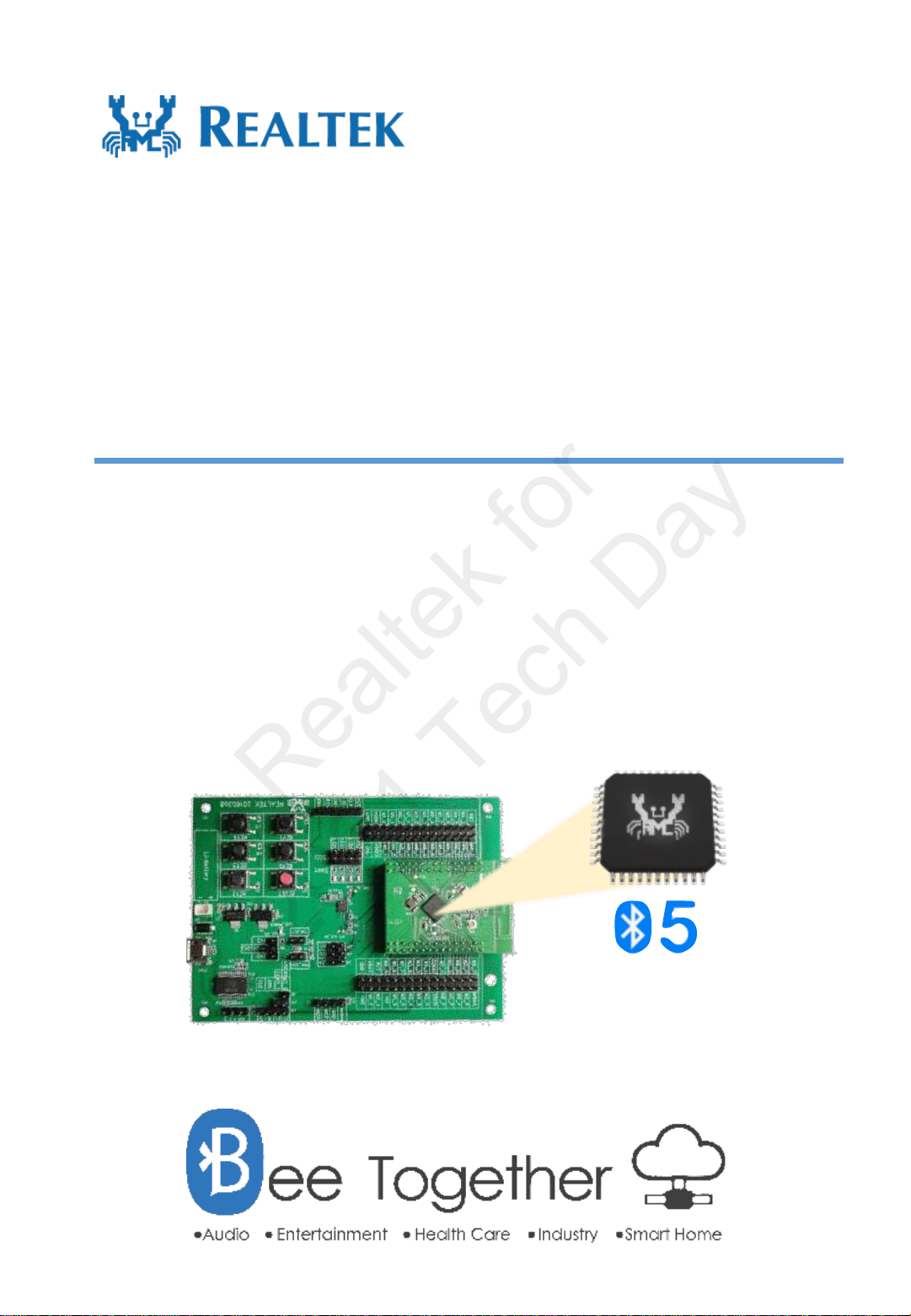
RTL8762D Evaluation Board User Manual
Copyright 2021 Realtek Semiconductor Corporation. All Rights Reserved.
3
Contents
Revision History.................................................................................................................................................2
Contents of Tables..............................................................................................................................................4
Contents of Figures.............................................................................................................................................5
1.RTL8762D Evaluation Board Introduction.........................................................................................................6
1.1 RTL8762D EVB introduction ......................................................................................................................6
1.2 Evaluation Board Interface ...........................................................................................................................6
1.2.1 Interface Description..............................................................................................................................6
1.2.2 Main Chip (Module) ..............................................................................................................................7
1.2.3 Power supply .........................................................................................................................................8
1.2.4 IO Port ...................................................................................................................................................9
1.2.5 Interface .................................................................................................................................................9
1.2.6 Others...................................................................................................................................................10
1.2.7 Pin Allocation on Motherboard of Evaluation Board ..........................................................................11
2.Development Board Operation Instructions......................................................................................................14
2.1 Acquiring Log with Onboard USB to UART Converter ............................................................................14
2.2 Current test..................................................................................................................................................14
2.3 6-axis Motion Sensor..................................................................................................................................15
Realtek for
2021 Tech Day