Rebel MIE-RB-806R User manual

TOOLS
model: MIE-RB-806R
USER’S
MANUAL
DE EN PL RO
WIRE TRACKER
WITH CABLE TESTER

DE 2

DE
3
SICHERHEITSANWEISUNGEN
1. Über rüfen Sie das Gehäuse vor der Verwendung des
Geräts auf mechanische Beschädigungen. Verwenden Sie
das Gerät nicht, wenn das Gehäuse Risse aufweist oder
Teile fehlen.
2. Verwenden Sie das Gerät nicht bei Tem eraturen, die den
angegebenen Bereich überschreiten, bei hoher
Luftfeuchtigkeit und in der Nähe von S rengstoen und
brennbaren Stoen.
3. Über rüfen Sie vor der Verwendung des Geräts die
Messleitungen auf Beschädigungen. Verwenden Sie das
Gerät nicht, wenn die Messleitungen Isolationsschäden
oder Schnitte aufweisen.
4. Geben Sie keine höheren S annungen als in der
S ezifikation angegeben ein.
5. Ändern Sie während der Messungen nicht die Position des
Modus-Auswahlschalters.
6. Vor dem Önen des Batteriegehäuses das Gerät
ausschalten.
7. Die Batterie muss durch eine neue mit derselben
S ezifikation ersetzt werden.
8. Mani ulieren Sie nicht die internen Schaltkreise des
Geräts. Dies kann zu einer Verringerung der Genauigkeit
oder zu einer Beschädigung des Geräts führen.
9. Das Gerät ist nur für den Innenbereich bestimmt.
10.Nehmen Sie die Batterie heraus, wenn das Gerät längere
Zeit nicht benutzt wird.
PRODUKTBESCHREIBUNG
Sender
1. Krokodilklemmen
2. RJ11 Stecker
3. RJ45 Buchse
4. LED Anzeige
5. Status LED
6. Taste AUSWAHL [SELECT]
7. Modus-Auswahlschalter
8. TESTLED [VERIFY-LED]
SELECT
STATUS
VERIFY
G
1
2
3
4
5
6
7
8
SCAN
OFF
TEST
1
2
3
4
6
5
7
8

DE 4
Em fänger
1. Sonde
2. LED Anzeige
3. Ko örerbuchse
4. Lautstärkeregler
5. Schalter für Arbeitslicht
6. Taste TEST
7. LED Anzeige
8. RJ45 Buchse
9. Lauts recher
BETRIEB
Über rüfen der Netzwerkkabel
1. Schließen Sie das Netzwerkkabel an die RJ45-Buchsen
von Sender und Em fänger an.
2. Stellen Sie den Modus-Auswahlschalter auf TEST.
3. Der Test des Netzwerkkabels beginnt. Wenn alle Drähte
durchgehend sind, leuchtet jede Diode gleichzeitig am
Sender und Em fänger auf. Wenn das Kabel geerdet ist,
leuchtet die G-Diode während des Tests auf.
4. Drücken Sie die Taste AUSWAHL [SELECT], um die
Prüfgeschwindigkeit zu ändern.
Suche nach Drähten in Kabeln
Das Messgerät kann in großen Kabelbündeln nach Drähten
suchen
1. Verbinden Sie den Krokodilcli oder RJ11 Stecker mit dem
Suchkabel.
2. Stellen Sie den Modus-Auswahlschalter auf die Position
SUCHEN [SCAN].
3. Verwenden Sie den Em fänger, um den Draht am anderen
Ende des Kabels zu finden. Halten Sie die Taste TEST gedrückt.
Wenn der Em fänger ein Geräusch macht, bedeutet dies, dass
Sie das gesuchte Kabel gefunden haben. Je lauter der Ton,
desto näher ist die Sonde an dem Draht, den Sie suchen.
4. Um den Ton zu ändern, drücken Sie die Taste AUSWAHL
[SELECT].
1
G
5
2
6
3
7
4
8
1
9
2
3
7
8
6
4
5

DE
5
Durchgangs rüfung
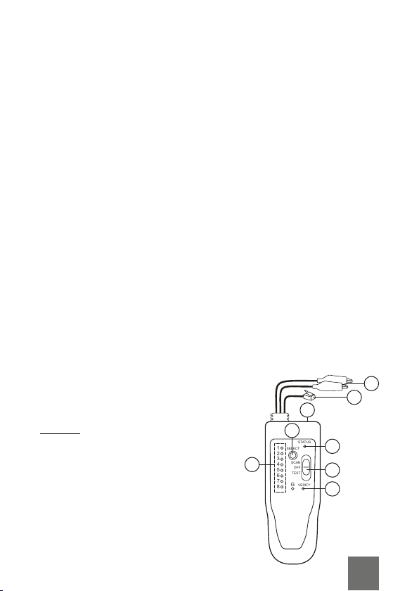
1. Verwenden Sie die Krokodilklemme oder RJ11 Stecker, um
den Kabeldurchgang zu über rüfen.
2. Stellen Sie den Modus-Auswahlschalter auf TEST.
3. Wenn die LEDs 1 und 8 leuchten (nacheinander), bedeutet
dies, dass der Durchgang erhalten bleibt.
Hinweis: Der RC11-Stecker hat 2 Drähte.
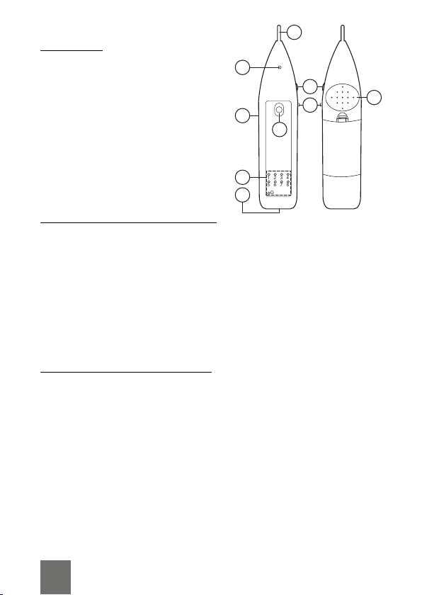
Gleichs annung rüfen
1. Stellen Sie den Modus-Auswahlschalter auf SUCHEN
[SCAN], halten Sie die Taste AUSWAHL [SELECT] gedrückt,
bis die TESTLED [VERIFY-LED]rot blinkt.
2. Schließen Sie die Krokodilklemmen an den Stromkreis an.
Wenn die STATUS-LED rot leuchtet, ist der rote
Krokodildraht mit dem Plus ol verbunden. Wenn die
STATUS-LED grün leuchtet, ist der rote Krokodildraht mit
dem Minus ol verbunden.
3. Die Lichtintensität der STATUS-LED ents richt dem
Widerstand.
TECHNISCHE DATEN
Haupteigenschaften
• Zwei Krokodilklemmen
• RJ11 Stecker
• Summer
• Betriebsanzeige am Em fänger
• Anzeige Niedrige Batterie
• Maximale Entfernung der Signalübertragung: 3 km
• Maximaler Arbeitsstrom des Senders: <9 mA
• Maximaler Arbeitsstrom des Em fängers: <28 mA
• Stromversorgung des Senders: 9 V Batterie
• Stromversorgung des Em fängers: 9 V Batterie
• Abmessungen des Senders: 125 x 47 x 25 mm
• Gewicht des Senders: 123 g
• Abmessungen des Em fängers: 172 x 36 x 25 mm
• Gewicht des Em fängers: 91 g
• Im Set: Sender, Em fänger, Ko örer, Tragetasche,
Bedienungsanleitung

DE 6
Deutsch
Korrekte Entsorgung ieses Pro ukts
(Elektromüll)
(Anzuwenden in den Ländern der Euro äischen Union und anderen
euro äischen Ländern mit einem se araten Sammelsystem)
Die Kennzeichnung auf dem Produkt bzw. auf der dazugehörigen Literatur gibt
an, dass es nach seiner Lebensdauer nicht zusammen mit dam normalem
Haushaltsmüll entsorgt werden darf. Entsorgen Sie dieses Gerät bitte getrennt
von anderen Abfällen, um der Umwelt bzw. der menschlichen Gesundheit nicht
durch unkontrollierte Müllbeseitigung zu schaden. Recyceln Sie das Gerät, um
die nachhaltige Wiederverwertung von stoichen Ressourcen zu fördern.
Private Nutzer sollten den Händler, bei dem das Produkt gekauft wurde, oder
die zuständigen Behörden kontaktieren, um in Erfahrung zu bringen, wie sie das
Gerät auf umweltfreundliche Weise recyceln können. Gewerbliche Nutzer
sollten sich an Ihren Lieferanten wenden und die Bedingungen des
Verkaufsvertrags konsultieren. Dieses Produkt darf nicht zusammen mit
anderem Gewerbemüll entsorgt werden.
Hergestellt in China für LECHPOL ELECTRONICS S . z o.o. S .k.,
ul. Garwolińska 1, 08-400 Miętne.
EN 6
Funktionen
• Leitungssucher
• Gleichs annungsdetektor
• Telefonkabeltest
• Netzwerkkabeltest
• Durchgangstest der Leitungen

DE
7
EN
7
SAFETY INSTRUCTIONS
1. Before using the device, ins ect the case for any
mechanical damage. If the case has cracks or is missing
any art, do not use the device.
2. Do not use the device in tem eratures exceeding the
range in s ecification, in high humidity, and near
ex losives and flammables.
3. Before using the device, check the test leads for any
insulation damage. If the test leads has insulation damage
or cuts, do not use the device.
4. Do not in ut voltages higher than said in the s ecification.
5. During measurements, do not change the osition of the
rotary switch.
6. Turn o the device before o ening the battery
com artment cover.
7. Battery must be re laced with a new one and with the
same s ecification.
8. Do not interfere with the device's internal aths. This may
lead to measurement decrease or damaging the device.
9. The device is intended for indoors use only.
10.Take out the batteries, if the device is not going to be used
for a long time.
PRODUCT DESCRIPTION
Transmitter
1. Crocodile cli
2. RJ11 connector
3. RJ45 socket
4. LED indicator
5. Status LED
6. SELECT button
7. Position switch
8. VERIFY LED
SELECT
STATUS
VERIFY
G
1
2
3
4
5
6
7
8
SCAN
OFF
TEST
1
2
3
4
6
5
7
8

EN 8
Receiver
1. Probe
2. Indicator LED
3. Ear hone jack
4. Volume control
5. Work light switch
6. TEST button
7. LED indicator
8. RJ45 socket
9. S eaker
OPERATION
Checking network cables
1. Connect network cable to the transmitter and receiver
RJ45 sockets.
2. Set the mode switch to TEST osition.
3. Network cable test will start If all wires have continuity,
each diode will light u on the transmitter and receiver
simultaneously. If the cable is grounded, the G diode will
light u during the test.
4. Press SELECT button to change checking s eed.
Searching for wires in cables
The meter can search for wires in large bundles of cables
1. Connect the crocodile cli or RJ11 to the searching wire.
2. Set the rotary switch to the SCAN osition.
3. Use the receiver to find the wire at the other end of the
wire. Press and hold TEST button. If the receiver makes a
sound, it means you have found the wire you are looking
for. The louder the sound, the closer the robe is to the
wire you are looking for.
4. To change the tone of the sound, ress the SELECT button.
Continuity checking
1. Use the crocodile cli or RJ11 to check the cable continuity.
2. Set the mode switch to TEST osition.
1
G
5
2
6
3
7
4
8
1
9
2
3
7
8
6
4
5

EN
9
3. If LEDs 1 and 8 are on (one after the other), it means that
continuity is maintained.
Note: RC11 connector has 2 wires.
Checking DC voltage
1. Set the mode switch to SCAN osition, ress and hold
SELECT button until VERIFY LED will blink red.
2. Connect the crocodile wires to the circuit. If the STATUS
LED lights u red, it means that the red crocodile wire is
connected to the ositive ole. If the STATUS LED lights u
green, it means that the red crocodile wire is connected to
the negative ole.
3. The light intensity of the STATUS LED corres onds to the
resistance.
SPECIFICATION
Main features
• Two crocodile cli s
• RJ11 lug
• Buzzer
• Work light on the receiver
• Low battery level indicator
• Maximum distance of signal transmission: 3 km
• Maximum working current of emitter: <9 mA
• Maximum working current of receiver: <28 mA
• Emitters ower: 9 V battery
• Receivers ower: 9 V battery
• Emitters dimensions: 125 x 47 x 25 mm
• Emitters weight: 123 g
• Receivers dimensions: 172 x 36 x 25 mm
• Receivers weight: 91 g
• In set: emitter, receiver, ear hones, carry ouch, owner's
manual

EN 10
PL 10
English
Correct Disposal of This Pro uct
(Waste Electrical & Electronic Equipment)
(A licable in the Euro ean Union and other Euro ean countries with se arate
collection systems) This marking shown on the roduct or its literature, indicates
that it should not be dis osed with other household wastes at the end of its
working life. To revent ossible harm to the environment or human health from
uncontrolled waste dis osal, lease se arate this from other ty es of wastes
and recycle it res onsibly to romote the sustainable reuse of material
resources. Household users should contact either the retailer where they
urchased this roduct, or their local government oce, for details of where
and how they can take this item for environmentally safe recycling. Business
users should contact their su lier and check the terms and conditions of the
urchase contract. This roduct should not be mixed with other commercial
wastes for dis osal.
Made in China for LECHPOL ELECTRONICS S . z o.o. S .k., ul. Garwolińska 1,
08-400 Miętne.
Functions
• Locating wires
• DC voltage detector
• Tele hone cables test
• Network cables test
• Wires continuity test

EN
11
PL
11
KWESTIE BEZPIECZEŃSTWA
1. Przed roz oczęciem korzystania z urządzenia należy
s rawdzić jego obudowę od kątem uszkodzeń
mechanicznych. Jeżeli obudowa osiada ęknięcia lub
braki, nie należy korzystać z urządzenia.
2. Nie należy korzystać z urządzenia w tem eraturach
rzekraczających zakres odany w s ecyfikacji, w
wysokiej wilgotności, w obliżu materiałów wybuchowych
oraz łatwo alnych.
3. Przed roz oczęciem korzystania z urządzenia należy
s rawdzić rzewody omiarowe od kątem uszkodzeń
izolacji. Jeżeli rzewody osiadają nacięcia lub
uszkodzenia izolacji, nie należy korzystać z urządzenia.
4. Nie należy w rowadzać do urządzenia na ięć wyższych
niż odanych w s ecyfikacji urządzenia.
5. Podczas dokonywania omiarów nie należy zmieniać
ustawienia rzełącznika trybu.
6. Przed otwarciem okrywy baterii należy wyłączyć
urządzenie.
7. Baterię należy wymieniać na nową, o takich samych
arametrach.
8. Nie należy ingerować w ścieżki wewnętrzne urządzenia.
Może to s owodować zmniejszenie dokładności
omiarów lub uszkodzenie urządzenia.
9. Urządzenie jest rzeznaczone do użytku wewnętrznego.
10.Jeżeli urządzenie nie będzie używane rzez dłuższy czas,
należy wyjąć z niego baterię.
OPIS URZĄDZENIA
Nadajnik
1. Złącza krokodylowe
2. Złącze RJ11
3. Gniazdo RJ45
4. Diody sygnalizujące
5. Dioda STATUS
6. Przycisk SELECT
7. Przełącznik wyboru trybu
8. Dioda VERIFY
SELECT
STATUS
VERIFY
G
1
2
3
4
5
6
7
8
SCAN
OFF
TEST
1
2
3
4
6
5
7
8

PL 12
Odbiornik
1. Próbnik
2. Dioda sygnalizująca
3. Gniazdo słuchawkowe
4. Pokrętło głośności
5. Przełącznik światła roboczego
6. Przycisk TEST
7. Diody sygnalizujące
8. Gniazdo RJ45
9. Głośnik
OBSŁUGA
S rawdzanie kabli sieciowych
1. Podłączyć kabel sieciowy do gniazd RJ45 nadajnika i
odbiornika.
2. Ustawić rzełącznik trybu do ozycji TEST.
3. Roz ocznie się test kabla sieciowego. Jeżeli wszystkie żyły
mają zachowaną ciągłość, każda dioda za ali się o kolei
na nadajniku i odbiorniku jednocześnie. Jeżeli kabel ma
uziemienie, odczas testu za ali się dioda G.
4. Aby zmienić szybkość s rawdzania należy nacisnąć
rzycisk SELECT.
Szukanie kabli we wiązkach
Miernik może wyszukiwać rzewody w dużych wiązkach kabli
1. Podłączyć złącze krokodylowe lub RJ11 do szukanego
rzewodu.
2. Ustawić rzełącznik wyboru trybu do ozycji SCAN.
3. Należy użyć odbiornika do znalezienia rzewodu na
drugim końcu wiązki. Należy nacisnąć i rzytrzymać
rzycisk TEST. Jeżeli odbiornik wyda dźwięk, oznacza to
znalezienie szukanego rzewodu. Im głośniejszy dźwięk,
tym bliżej znajduje się róbnik od szukanego rzewodu.
4. Aby zmienić ton wydawanego dźwięku należy nacisnąć
rzycisk SELECT.
1
G
5
2
6
3
7
4
8
1
9
2
3
7
8
6
4
5

S rawdzanie ciągłości
1. Do s rawdzenia ciągłości rzewodów należy użyć złącz
krokodylowych lub złącza RJ11.
2. Ustawić rzełącznik trybu do ozycji TEST.
3. Jeżeli świecą diody 1 i 8 ( o kolei) oznacza to że
zachowana jest ciągłość.
Uwaga: złącze RJ11 osiada dwie żyły.
S rawdzanie na ięcia DC
1. Ustawić rzełącznik trybu do ozycji SCAN i nacisnąć i
rzytrzymać rzycisk SELECT, aż dioda VERIFY zacznie
migać na czerwono.
2. Podłączyć rzewody krokodylowe do biegunów ścieżki.
Jeżeli dioda STATUS świeci na czerwono, oznacza to że
czerwony rzewód krokodylowy jest odłączony do
bieguna dodatniego. Jeżeli dioda STATUS świeci na
zielono, oznacza to że czerwony rzewód krokodylowy
jest odłączony do bieguna ujemnego.
3. Intensywność świecenia diody STATUS od owiada
rezystancji.
PL
13
SPECYFIKACJA
Główne cechy
• Dwa złącza krokodylowe
• Złącze RJ11
• Głośnik
• Światło robocze odbiornika
• Wskaźnik niskiego oziomu baterii
• Maksymalny dystans transmisji: 3 km
• Maksymalny rąd racy nadajnika: <9 mA
• Maksymalny rąd racy odbiornika: <28 mA
• Zasilanie nadajnika: bateria 9 V
• Zasilanie odbiornika: bateria 9V
• Wymiary nadajnika: 125 x 47 x 25 mm
• Waga nadajnika: 123 g

RO 14
PL 14
Polan
Prawi łowe usuwanie pro uktu
(zużyty sprzęt elektryczny i elektroniczny)
Oznaczenie umieszczone na rodukcie lub w odnoszących się do niego
tekstach wskazuje, że o u ływie okresu użytkowania nie należy usuwać z
innymi od adami ochodzącymi z gos odarstw domowych. Aby uniknąć
szkodliwego w ływu na środowisko naturalne i zdrowie ludzi wskutek
niekontrolowanego usuwania od adów, rosimy o oddzielenie roduktu od
innego ty u od adów oraz od owiedzialny recykling w celu romowania
onownego użycia zasobów materialnych jako stałej raktyki. W celu uzyskania
informacji na temat miejsca i s osobu bez iecznego dla środowiska recyklingu
tego roduktu użytkownicy w gos odarstwach domowych owinni
skontaktować się z unktem s rzedaży detalicznej, w którym dokonali zaku u
roduktu, lub z organem władz lokalnych. Użytkownicy w firmach owinni
skontaktować się ze swoim dostawcą i s rawdzić warunki umowy zaku u.
Produktu nie należy usuwać razem z innymi od adami komercyjnymi.
Wy rodukowano w CHRL dla LECHPOL ELECTRONICS S . z o.o. S .k.,
ul. Garwolińska 1, 08-400 Miętne.
• Wymiary odbiornika: 172 x 36 x 25 mm
• Waga odbiornika: 91 g
• W zestawie: nadajnik, odbiornik, słuchawki, okrowiec,
instrukcja obsługi
Funkcje
• Lokalizowanie oszukiwanych rzewodów
• Wskaźnik na ięcia DC
• Test kabli linii telefonicznych
• Test kabli sieciowych
• Test ciągłości rzewodów

RO
15
INSTRUCȚIUNI PRIVIND SIGURANȚA
1. Înainte de a utiliza dis ozitivul, ins ectați carcasa entru
eventualele deteriorări mecanice. Dacă carcasa are fisuri
sau iese li să, nu utilizați dis ozitivul.
2. Nu utilizați dis ozitivul la tem eraturi care de ășesc
intervalul s ecificat, în medii cu umiditate ridicată, în
a ro ierea materialelor ex lozibile sau inflamabile.
3. Înainte de a utiliza dis ozitivul, verificați dacă cablurile de
testareau izolația deteriorată. Dacă cablurile de testare au
izolația deteriorată sau tăieturi, nu utilizați dis ozitivul.
4. Nu măsurați tensiuni mai mari decât cele indicate în
s ecificații.
5. În tim ul măsurătorilor, nu modificați oziția comutatorului
rotativ.
6. O riți dis ozitivul înainte de a deschide ca acul
com artimentului entru baterii.
7. Bateria trebuie înlocuită cu una nouă, care are aceleași
s ecificații.
8. Nu schimbați circuitele interne ale dis ozitivului. Acest
lucru ar utea duce la măsurare greșită sau la deteriorarea
dis ozitivului.
9. Dis ozitivul este roiectat entru a se utiliza doar în
interior.
10.Scoateți bateriile atunci când nu folosiți dis ozitivul o
erioadă mai lungă de tim .
DESCRIEREA PRODUSULUI
Transmițător
1. Clemă ti crocodil
2. Conector RJ11
3. Mufă RJ45
4. Indicator LED
5. Stare LED
6. Buton SELECT
7. Comutator rotativ
8. LED VERIFY
SELECT
STATUS
VERIFY
G
1
2
3
4
5
6
7
8
SCAN
OFF
TEST
1
2
3
4
6
5
7
8
PL
15

RO 16
Rece tor
1. Sondă
2. Indicator LED
3. Mufă entru căști
4. Control volum
5. Comutator lumină de lucru
6. Buton TEST
7. Indicator LED
8. Mufă RJ45
9. Difuzor
FUNCȚIONARE
Verificarea cablurilor de rețea
1. Conectați cablul de rețea la mufa RJ45 a transmițătorului și
a rece torului.
2. Setați comutatorul de mod în oziția TEST.
3. Testarea cablurilor de rețea înce e cu verificarea
continuității firelor, fiecare diodă se va a rinde simultan e
emițător și rece tor. Dacă cablul este ământat, dioda G se
va a rinde în tim ul testării.
4. A ăsați butonul SELECT entru a modifica viteza de
verificare.
Căutarea firelor în cabluri
Multimetrul oate căuta fire într-o legătură mare de cabluri.
1. Conectați clema ti crocodil sau mufa RJ11 la firul căutat.
2. Setați comutatorul rotativ în oziția SCAN.
3. Folosiți rece torul entru a găsi firul de la celălalt ca ăt al
firului. A ăsați ți țineți a ăsat butonul TEST. Dacă
rece torul emite un sunet, înseamnă că ați găsit firul e
care îl căutați. Cu cât sunetul este mai uternic, cu atât
sonda este mai a roa e de firul e care îl căutați.
4. Pentru a schimba tonul sunetului, a ăsați butonul SELECT.
1
G
5
2
6
3
7
4
8
1
9
2
3
7
8
6
4
5

Verificare continuitate
1. Utilizați mufa ti crocodil sau RJ11 entru a verifica
continuitatea cabului.
2. Setați comuatorul de mod în oziția TEST.
3. Dacă LED-urile 1 și 8 sunt a rinse (unul du ă altul),
înseamnă că este continuitate.
Notă: Conectorul RC11 are 2 fire.
Verificare tensiune DC
1. Setați comutatorul mod în oziția SCAN, a ăsați și țineți
a ăsat butonul SELECT ână când LED-ul VERIFY âl âie
roșu.
2. Conectați firele ti crocodil la circuit. DACĂ LED-ul STATUS
se a rinde roșu, înseamnă că firul roșu ti crocodil este
conectat la olul ozitiv. Dacă LED-ul STATUS se a rinde
verde, înseamnă că firul roșu ti crocodil este conectat la
olul negativ.
3. Intensitatea luminii LED-ului STATUS cores unde nivelului
rezistenței.
RO
17
SPECIFICAȚII
Caracteristici rinci ale
• Două cleme ti crocodil
• Mufă RJ11
• Alarmă
• Lam ă de lucru e rece tor
• Indicator de nivel scăzut al bateriei
• Distanța maximă de transmitere a semnalului: 3 km
• Curentul maxim de lucru al emițătorului: <9 mA
• Curentul maxim de lucru al rece torului: <28 mA
• Alimentare emițător: baterie 9 V
• Alimentare rece tor: baterie 9 V
• Dimensiuni emițător: 125 x 47 x 25 mm
• Greutate emițător: 123 g
• Dimensiuni rece tor: 172 x 36 x 25 mm
• Greutate rece tor: 91 g

RO 18
Romania
Reciclarea corecta a acestui pro us
(rezi uuri provenin in aparatura electrica si electronica)
Marcajale de e acest rodus sau mentionate in instructiunile sale de folosire
indica fa tul ca rodusul nu trebuie aruncat im reuna cu alte reziduuri din
gos od arie atunci cand nu mai este in stare de functionare. Pentru a reveni
osibile efecte daunatoare asu ra mediului inconjurator sau a san ata tii
oamenilor datorate evacuarii necontrolate a reziduurilor, vă rugăm să se arați
acest rodus de alte ti uri de reziduuri si să-l reciclati in mod res onsabil entru
a romova refolosirea resurselor materiale. Utilizatorii casnici sunt rugati să ia
legatura fie cu distribuitorul de la care au achizitionat acest rodus, fie cu
autoritatile locale, entru a rimi informatii cu rivire la locul si modul in care ot
de ozita acest rodus in vederea reciclarii sale ecologice. Utilizatorii
institutionali sunt rugati să ia legatura cu furnizorul și să verifice condițiile
sti ulate in contractul de vanzare. Acest rodus nu trebuie amestecat cu alte
reziduuri de natura comerciala.
Distribuit de Lech ol Electronic SRL, Re ublicii nr. 5, Resita, CS, ROMANIA
• Setul include: emițător, rece tor, căști, husă de trans ort,
manual de utilizare
Funcții
• Localizarea firelor
• Detector tensiune DC
• Testare cablu de telefon
• Testare cablu de rețea
• Test continuitate cabluri

RO
19

www.rebelelectro.com
Table of contents
Languages:
Other Rebel Power Tools manuals
Popular Power Tools manuals by other brands

Jet
Jet JWJ-8HH Operating instructions and parts manual

SteelMax
SteelMax SM-BM-16 Operator's manual

Scheppach
Scheppach HF60 Translation of original instruction manual

Bosch
Bosch GDR 10,8 V-EC Professional Original instructions

Ratio
Ratio SR800NM instruction manual

stayer
stayer CD125 operating instructions