SteelMax SM-BM-16 User manual

The tools of innovation.
15335 E. Fremont Drive, Centennial, CO 80112
1–87STEELMAX, FAX 303–690–9172
www.steelmax.com [email protected]
OPERATOR’S MANUAL
S
SM
M-
-B
BM
M-
-1
16
6
BEVELING MACHINE

Contents
1. GENERAL INFORMATION............................................................................................... 3
1.1. Application................................................................................................................. 3
1.2. Technical data............................................................................................................ 3
1.3. Equipment included ................................................................................................... 4
1.4. Dimensions................................................................................................................ 4
1.5. Design ....................................................................................................................... 5
2. SAFETY PRECAUTIONS.................................................................................................. 6
3. STARTUP AND OPERATION........................................................................................... 8
3.1. Removing and installing the roller and the milling head.............................................. 8
3.2. Adjusting the bevel parameters.................................................................................10
3.3. Adjusting the guide for beveling with radius ..............................................................11
3.4. Preparing..................................................................................................................11
3.5. Operating..................................................................................................................12
3.6. Replacing the cutting inserts.....................................................................................13
3.7. Replacing the brushes ..............................................................................................14
4. ACCESSORIES...............................................................................................................15
4.1. Guide for beveling pipes ...........................................................................................15
4.2. Anti-scratch guide sticker..........................................................................................17
4.3. Worktable fixture.......................................................................................................17
4.4. Radius insert positioner.............................................................................................21
4.5. Milling tools...............................................................................................................22
5. SPARE AND WEARING PARTS......................................................................................23
6. WIRING DIAGRAM..........................................................................................................24
7. EXPLODED DRAWINGS AND PARTS LIST....................................................................25
8. DECLARATION OF CONFORMITY.................................................................................31
9. WARRANTY CARD..........................................................................................................32
SM-BM-16
SM-BM-16 Operator’s Manual
3
1. GENERAL INFORMATION
1.1. Application
The BM-16 is a beveling machine designed to mill edges of plates and pipes made of
steel, aluminum alloys, brass, or plastics.
Depending on the milling head used the machine allows you to bevel workpieces
at the angle of 22.5°, 30°, 37.5°, 45°, 50°, 55°, 60°, or 65°. The minimum workpiece
thickness is 1.5 mm (0.06″). The maximum bevel width is 16 mm (0.63″). A radius
milling head allows you to bevel with a radius of 2, 3, 4, or 5 mm. The minimum
diameter of a hole to be machined is 40 mm (1.57″).
An optional guide allows you to bevel pipes, a sticker prevents scratches of the
aluminum workpieces, and a worktable fixture allows you to bevel flat bars.
1.2. Technical data
Voltage
1~ 220–240 V, 50–60 Hz
1~ 110–120 V, 50–60 Hz
Power
2200 W
Rotational speed (without load)
1800–5850 rpm
Protection level
IP 20
Protection class
II
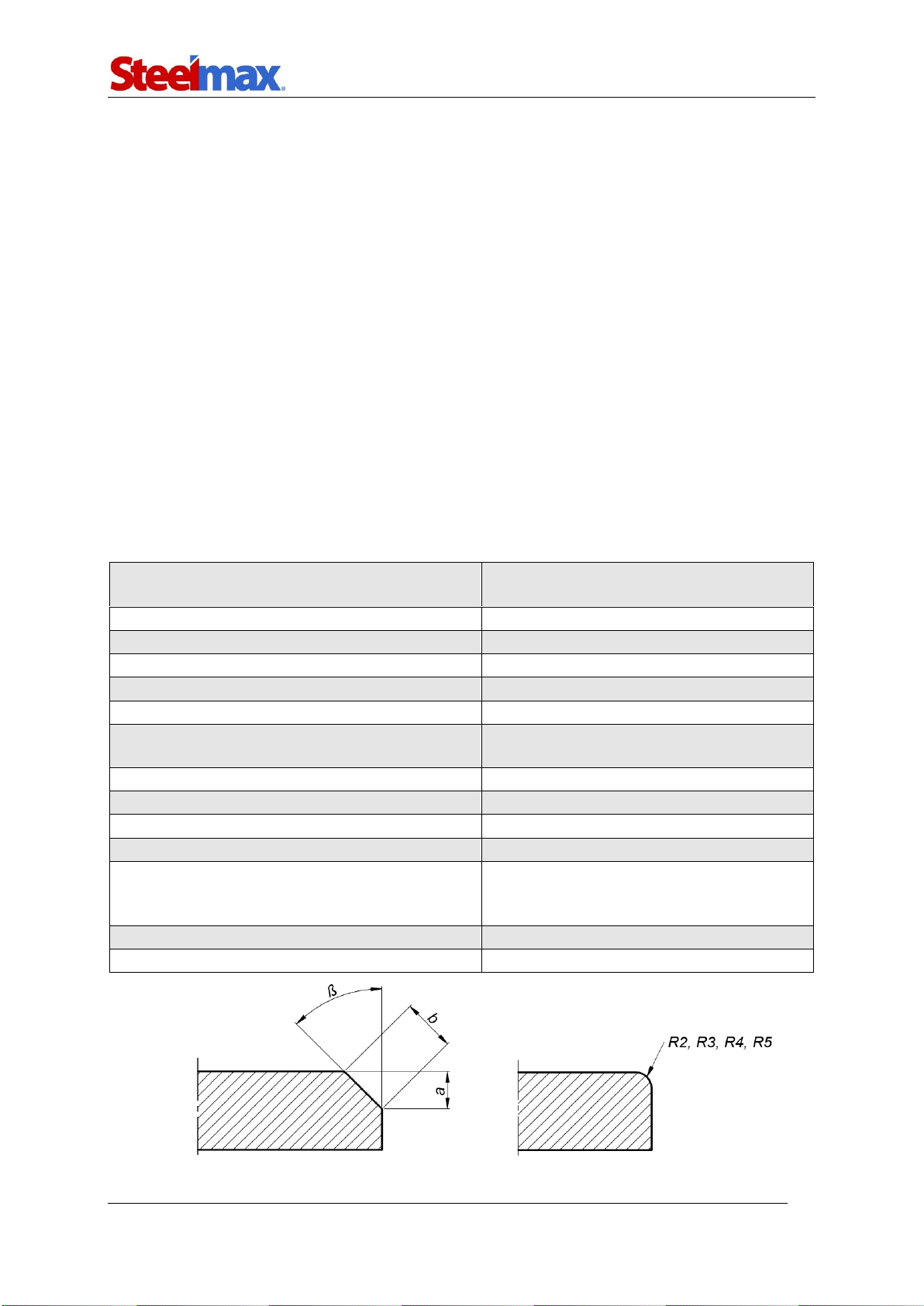
Maximum bevel width (b)
16 mm (0.63″, Fig. 1)
Bevel angle (ß, depends on the milling head)
22.5°, 30°, 37.5°, 45°, 50°, 55°, 60°, 65°
(Fig. 1)
Minimum workpiece thickness for beveling
1.5 mm (0.06″)
Minimum hole diameter
40 mm (1.57″)
Edge radius
2 mm, 3 mm, 4 mm, 5 mm (Fig. 1)
Noise level
More than 70 dB
Vibration level
2.3 m/s2(7.5 ft/s2)
Machine harmful for health. Take periodic
breaks during work.
Required ambient temperature
0–40°C (34–104°F)
Weight (without milling head)
10 kg (22 lbs)
Fig. 1. Bevel dimensions
SM-BM-16
SM-BM-16 Operator’s Manual
4
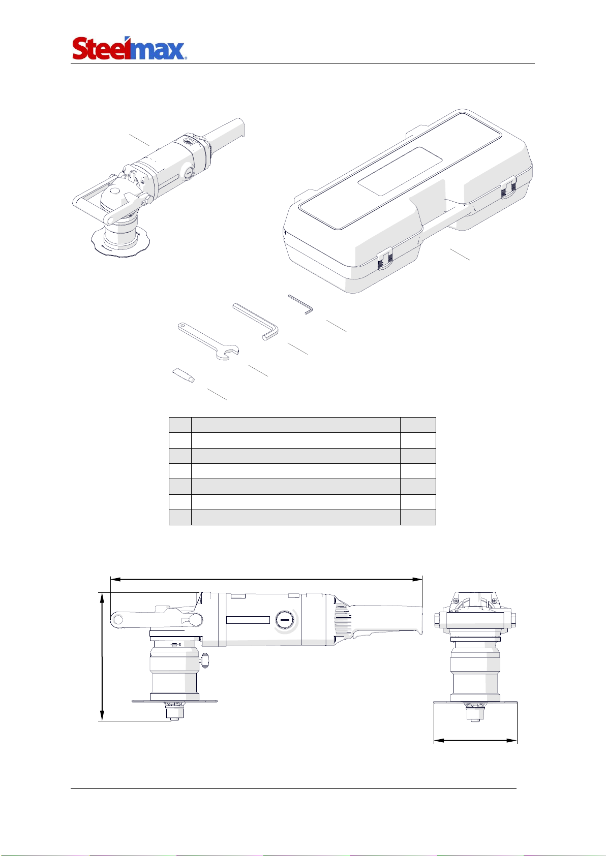
1.3. Equipment included
1
Beveling machine (without milling head)
1 unit
2
Plastic box
1 unit
3
5 mm hex wrench
1 unit
4
14 mm hex wrench
1 unit
5
32 mm flat wrench
1 unit
6
Grease for screws (5 g, 0.17 oz)
1 unit
–
Operator’s Manual
1 unit
1.4. Dimensions
1
3
4
5
2
6
585 mm (23″)
241 mm (9.4″)
156 mm (6.1″)
SM-BM-16
SM-BM-16 Operator’s Manual
5
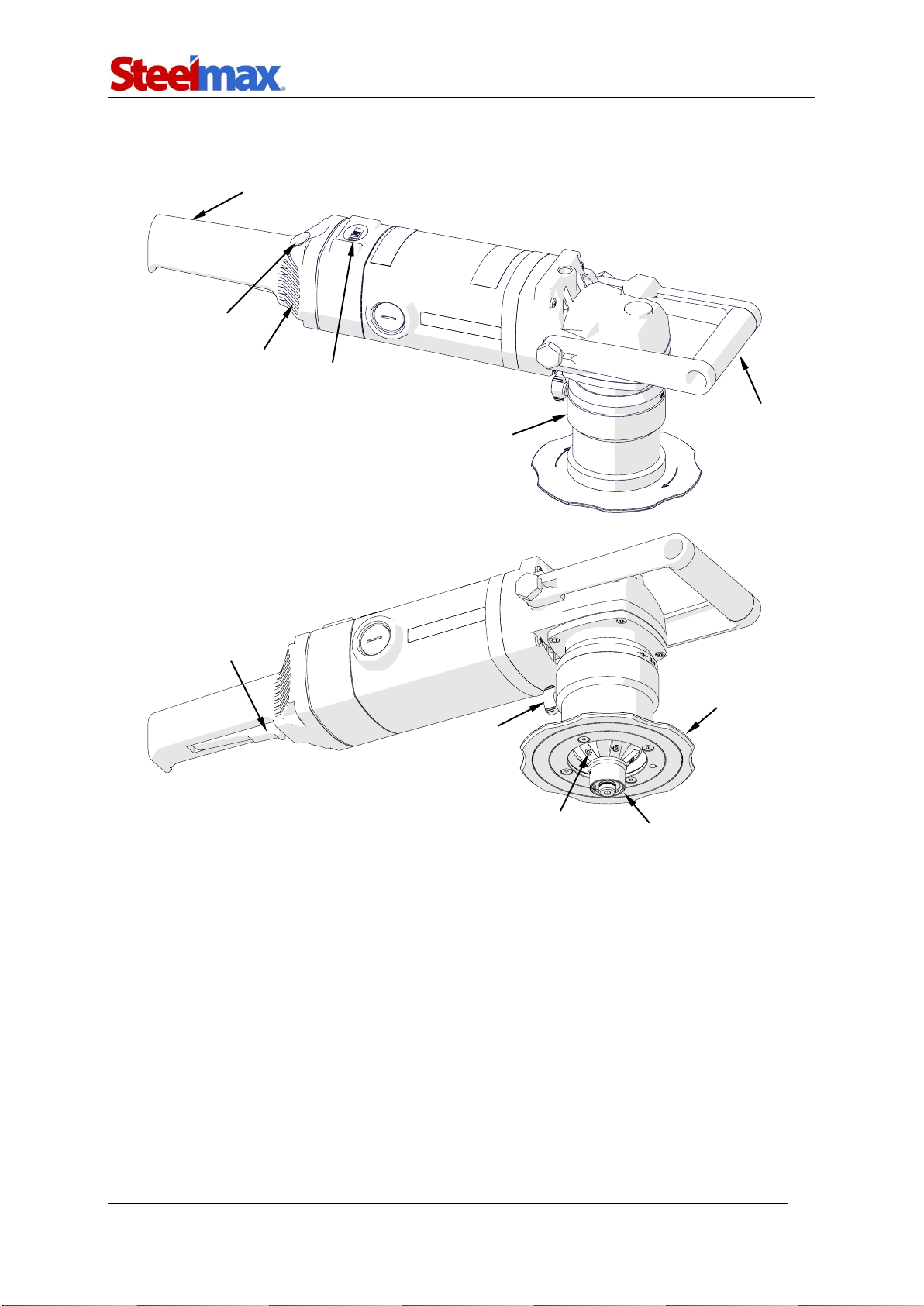
1.5. Design
Speed dial
Handle
Handle
Switch lock
ON/OFF switch
Guide
Clamping
screw
Milling head
Guiding roller
Sleeve
Air vents

SM-BM-16
SM-BM-16 Operator’s Manual
6
2. SAFETY PRECAUTIONS
1. Before use, read this Operator’s Manual and complete a training in occupational
safety and health.
2. Use only in applications specified in this Operator’s Manual.
3. Make sure that the machine has all parts and they are genuine and not damaged.
4. Make sure that the specifications of the power source are the same as those
specified on the rating plate.
5. Do not carry the machine by the cord and do not pull the cord. This can cause
damage and electric shock.
6. Keep untrained bystanders away from the machine.
7. Before each use, ensure the correct condition of the machine, power source,
power cord, plug, control parts, and milling tools.
8. Before each use, make sure that no part cracked or loose. Make sure to maintain
correct conditions that can have an effect on the operation of the machine.
9. Keep the machine dry. Do not expose the machine to rain, snow, or frost.
10. Keep the work area well-lit, clean, and free of obstacles.
11. Do not use near flammable materials, or in explosive environments.
12. Use only tools specified in this Operator’s Manual.
13. Do not use tools that are dull or damaged.
14. Make sure that the cutting inserts and the milling head are correctly attached.
Remove wrenches from the work area before you connect the machine to the
power source.
15. Do not use the machine so that the milling head points up.
16. If the cutting edge of an insert is worn, rotate the insert by 90° or 180°. If all
possible to use edges are worn, install new inserts specified in this Operator’s
Manual.
17. Use eye and ear protection, non-skid footwear, and protective clothing. Do not
use loose clothing.
18. Do not touch chips or moving parts. Do not let anything catch in moving parts.
19. After each use, clean the machine and the milling head with a cotton cloth and no
chemical agents. Do not remove chips with bare hands.
20. Maintain the machine and install/remove parts and tools only after you unplug the
machine from the power source.

SM-BM-16
SM-BM-16 Operator’s Manual
7
21. Repair only in a service center appointed by the seller.
22. If the machine falls, is wet, or has any damage, stop the work and promptly send
the machine to the service center for check and repair.
23. If you are not going to use the machine, remove it from the worksite and keep it in
a safe and dry place.
24. If you are not going to use the machine for an extended period, put anti-corrosion
material on the steel parts.

SM-BM-16
SM-BM-16 Operator’s Manual
8
3. STARTUP AND OPERATION
3.1. Removing and installing the roller and the milling head
Unplug the machine from the power source. To remove the roller and the milling
head, continue in the sequence that follows.
To install the roller and the milling head, remove the sleeve as shown before. Then,
continue in the sequence that follows.
1
2
5
4
3
5 mm
32 mm
14 mm

SM-BM-16
SM-BM-16 Operator’s Manual
9
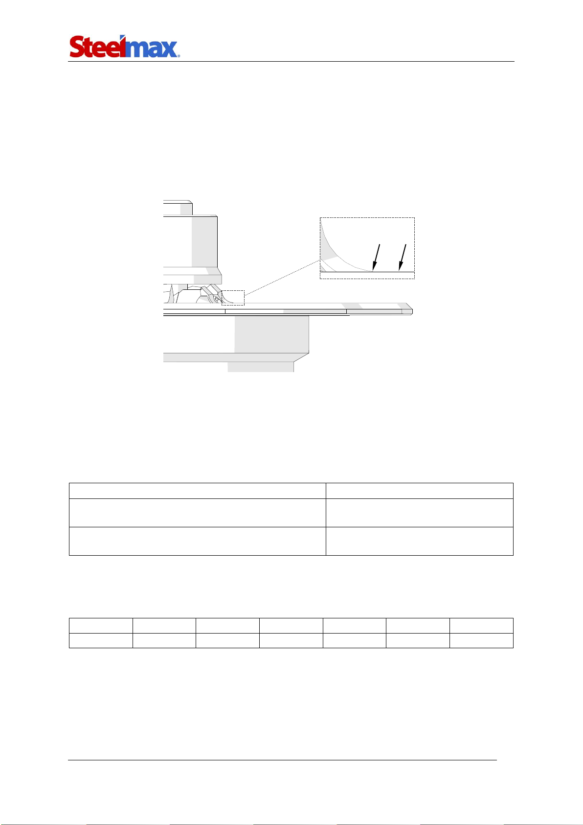
When you assemble the roller with the pivot pin (4), use such a number of
0.5-mm and 0.1-mm washers to keep a small gap between the roller and the cutting
inserts (6). The number of washers needed depends on the milling head installed.
Each time you install the milling head, adjust the gap between the roller and the
cutting inserts. Put all unused washers between the pivot pin and the roller (4).
6
CORRECT
✓
INCORRECT
(collision
between the
roller and the
cutting insert)
INCORRECT
(too large gap
between the
roller and the
cutting insert)
5 mm
32 mm
14 mm
4
Unused
washers
Distance
washers
3
2
5
7
8
1

SM-BM-16
SM-BM-16 Operator’s Manual
10
3.2. Adjusting the bevel parameters
Unplug the machine from the power source. Next, loosen the clamping screw (1) and
rotate the sleeve (2) so that the scale (3) shows the required bevel height ‘a’ (Tab. 1).
Then, tighten the screw (1).
Milling head
22.5°
30°
37.5°
45°
50°
55°
60°
65°
Height ‘a’ [mm]
Width ‘b’ [mm]
1
0.7
1.4
1.6
2.3
2.9
3.7
2
1.2
2.0
2.8
3.1
4.0
4.9
6.1
3
1.1
2.3
3.2
4.2
4.7
5.8
6.9
8.5
4
2.3
3.5
4.5
5.7
6.2
7.5
8.9
10.8
5
3.4
4.6
5.7
7.1
7.8
9.3
10.9
13.2
6
4.5
5.8
7.0
8.5
9.3
11.0
12.9
15.5
7
5.6
6.9
8.3
9.9
10.9
12.8
14.9
8
6.7
8.1
9.5
11.3
12.4
14.5
9
7.7
9.3
10.8
12.7
14.0
16.3
10
8.8
10.4
12.1
14.1
15.6
11
9.9
11.6
13.3
15.6
11.5
10.4
12.2
13.9
16.3
12
11.0
12.7
14.6
13
12.1
13.9
15.8
Tab. 1. Relation between the bevel width and height of the available milling heads
1
2
3
SM-BM-16
SM-BM-16 Operator’s Manual
11
3.3. Adjusting the guide for beveling with radius
Unplug the machine from the power source. Loosen the clamping screw and rotate
the sleeve to put the surface (1)on the same level as the radial cutting edge (2). You
can also use an optional radius insert positioner to set the guide correctly. Next,
tighten the clamping screw. Then, bevel a test edge and if necessary adjust the
position of the guide again.
3.4. Preparing
Install a milling head with the cutting inserts, and set the required bevel parameters.
Then, use the speed dial to set the speed that matches the type of the workpiece
(Tab. 2).
Material type
Rotational speed
Aluminum, brass, plastics
Setting 6 (5850 rpm)
Structural steel of standard quality, quality steel
Settings 3–5 (3100–4500 rpm)
Tab. 2. Recommended rotational speeds
The speed dial allows continuous control of the rotational speed in the range of
1800–5850 rpm.
Setting
1
2
3
4
5
6
Speed
1800 rpm
2400 rpm
3100 rpm
3800 rpm
4500 rpm
5850 rpm
To machine structural steel of standard quality or quality steel, set the speed to 4
and decrease the speed if much sparking occurs.
2
1
SM-BM-16
SM-BM-16 Operator’s Manual
12
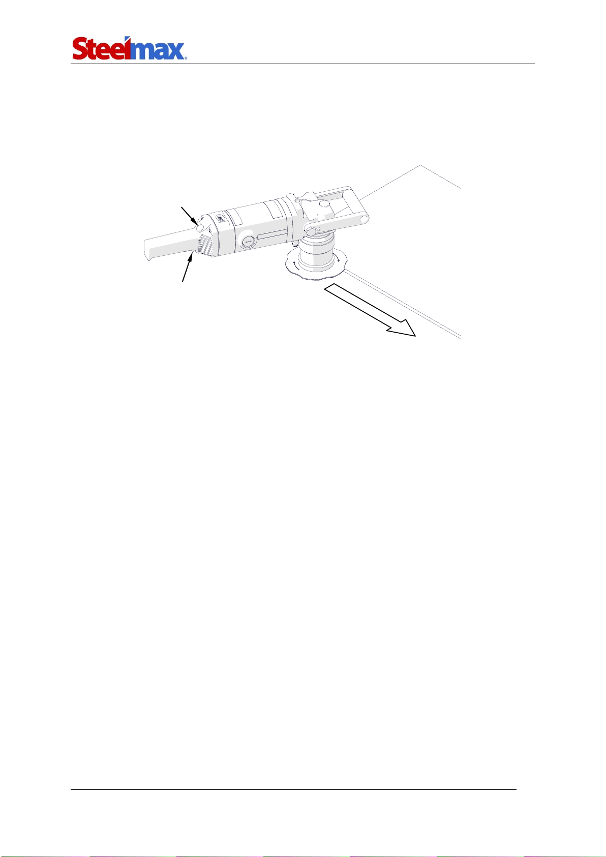
3.5. Operating
Connect the machine to the power source and put the machine on the left side of the
workpiece as shown in the figure. Make sure that the milling head is not in contact
with the workpiece. Make sure that the workpiece is stable and well clamped.
To start the motor, press and hold the switch lock and the ON/OFF switch, and
then release the lock. Wait a few seconds until the machine reaches the required
rotational speed. Then, press the machine to the workpiece with both hands and
slowly move to the edge until the tool starts cutting. Move the machine from left to
right (counter-rotation). The arrow on the guide shows the rotation direction of the
milling head.
Start with making small bevels (3–4 mm, 0.12–0.16″) and increase the bevel
width with experience. Bevel in at least two passes. Set the bevel width to a value
that will allow the feed of one meter per minute without much effort.
If an overload occurs, the motor stops. This can happen when the bevel width is
too large for the hardness of material or when the cutting inserts are dull. Thus, to
prevent overload, machine hard materials in multiple passes and replace the inserts
before they become dull. Also, take periodic breaks during work and keep the air
vents unclogged. This prevents overheating and damage to the windings.
After the work is finished, release the ON/OFF switch to turn off the motor. Then,
wait until the rotation stops and unplug the machine from the power source.
Clean the machine with a cotton cloth and no chemical agents.
Feed direction
Switch lock
ON/OFF switch

SM-BM-16
SM-BM-16 Operator’s Manual
13
3.6. Replacing the cutting inserts
Unplug the machine from the power source. Loosen the clamping screw (1)to get
access to the milling head. Then, rotate the sleeve to the right to lower it as far as
possible (2). Then, use the screwdriver supplied with the milling head to remove the
screw (3) and the cutting insert (4). Clean the socket, and then rotate the insert and
install again or replace with a new one if all possible to use edges are worn. Next,
push and tighten the insert. Make sure that the bottom of the insert is in full contact
with the surface of the socket (5).
Before you replace the cutting inserts of the radius milling head, loosen the roller
as described in “Removing and installing the roller and the milling head”.
Clean the threads once aweek. If necessary, put grease on the fixing screws for
inserts. Use an agent (for example copper paste) that prevent blocking of the screws.
3
1
2
4
5
INCORRECT
CORRECT
CORRECT

SM-BM-16
SM-BM-16 Operator’s Manual
14
3.7. Replacing the brushes
Every 200 work hours, check the condition of the carbon brushes. To do this, unplug
the machine from the power source, and then remove the cap and the brush. If the
length of the brush is less than 10 mm (0.4″), replace both brushes with new ones.
To install brushes, continue in reverse sequence. Then, let the motor operate
without load for 20 minutes.

SM-BM-16
SM-BM-16 Operator’s Manual
15
4. ACCESSORIES
4.1. Guide for beveling pipes
Allows external beveling of pipes with diameters of at least 150 mm (5.9″) and inter-
nal beveling of pipes with diameters of at least 110 mm (4.3″).
To install, unplug the machine from the power source. Use heat to increase the
temperature of the screws. Next, use the torx screwdriver to remove the standard
guide, and then install the guide for pipes.
Part number:
PRW-0509-07-00-00-0
(includes: four M5x12 screws,
torx screwdriver, 6 mm hex wrench)

SM-BM-16
SM-BM-16 Operator’s Manual
16
Rotate the sleeve to set ‘0’ on the scale (1). Use the 6 mm hex wrench to loosen the
rollers (2) and move them away from each other as far as possible. Put the pipe
vertically and put the machine onto the pipe. Press the roller (3) to the pipe and move
the rollers (4) equally to the pipe. Tighten the rollers in this position. Next, move the
machine from the pipe and set the required parameters (5). Then, start the machine,
slowly move it to the pipe, and bevel in the direction (6).
2
2
1
3
4
4
6
5

SM-BM-16
SM-BM-16 Operator’s Manual
17
Part number:
ZBD-0509-12-00-00-0
(includes 5 mm hex wrench)
4.2. Anti-scratch guide sticker
Self-adhesive guide sticker prevents scratches of the aluminum workpieces. After
you remove the sticker, clean excess glue from the guide with petroleum ether.
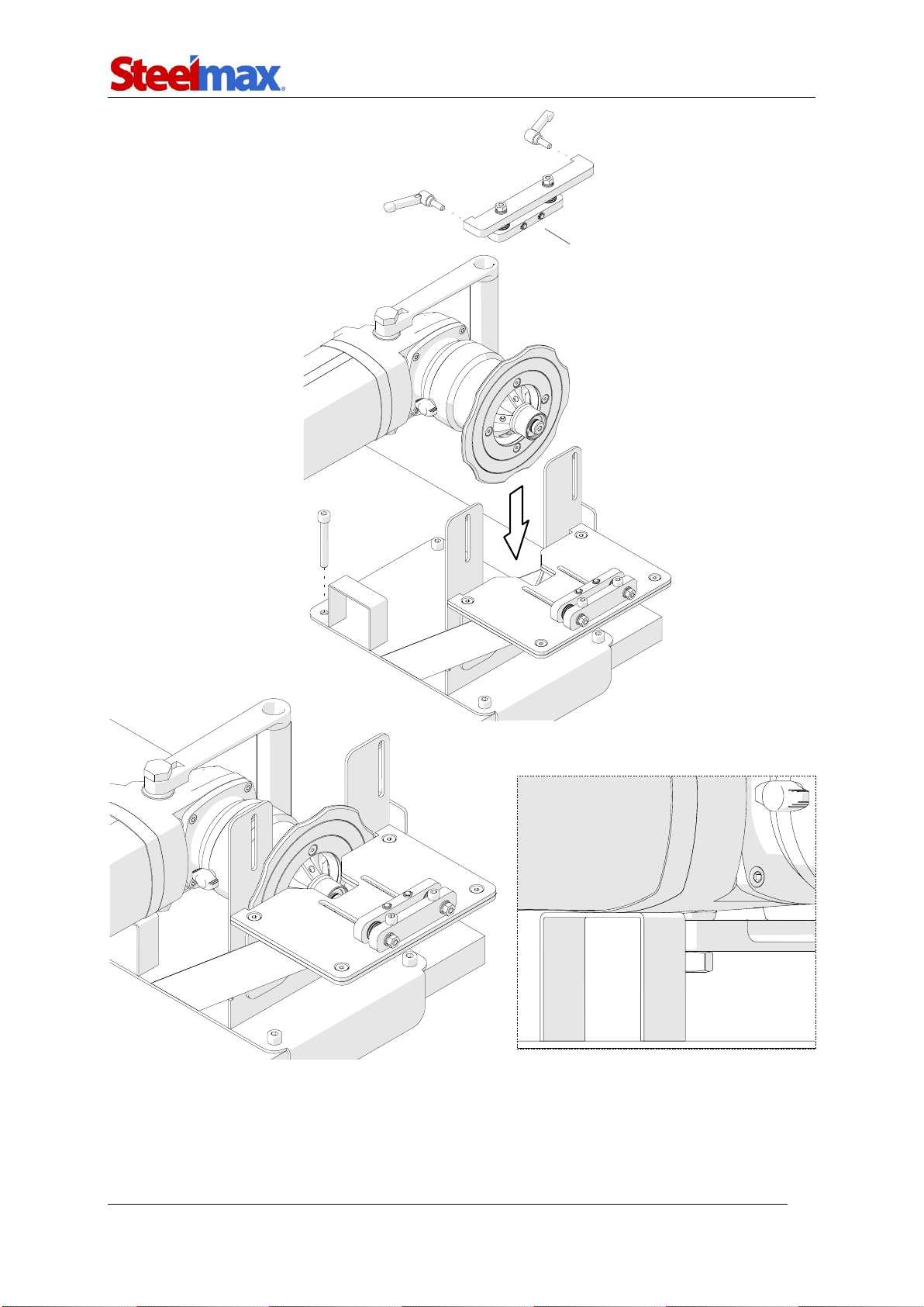
4.3. Worktable fixture
Designed to bevel workpieces with cross section of at least 15×25 mm (0.6×1″) and
length of at least 400 mm (16″). The width of the workpiece can be up to 100 mm
(4″), and height up to 65 mm (2.5″). The maximum bevel width is 14 mm (0.55″).
Install the worktable fixture by using holes in the base (1). Then, remove the levers
and remove the vertical clamp (2). Unplug the machine from the power source, and
rotate the sleeve to set ‘0’ on the scale. Next, put the machine with a beveling milling
head into the worktable fixture (3) so that the motor is on the support (4).
Part number:
NKL-0509-05-00-00-0
SM-BM-16
SM-BM-16 Operator’s Manual
18
2
1
3
4

SM-BM-16
SM-BM-16 Operator’s Manual
19
3
1
2
4
5
Use the 5 mm hex wrench to loosen the horizontal clamp (1), and then put the
workpiece (2) so that it makes contact with the guide (3). Next, move the horizontal
clamp to the workpiece (4) and tighten the screws in this position (5).

SM-BM-16
SM-BM-16 Operator’s Manual
20
Lightly tighten the levers (1) to install the vertical clamp (2). Move the clamp to
the workpiece (3) and tighten the levers in this position (4). Next, remove the work-
piece and set the required bevel parameters. Then, use the 5 mm hex wrench to
tighten the screws (5) to clamp the machine.
Start the machine and set the required rotational speed. Then, put the workpiece
on the left and bevel in the direction (6).
3
1
2
5
6
4
Other manuals for SM-BM-16
1
Table of contents
Other SteelMax Power Tools manuals


Popular Power Tools manuals by other brands


Bosch
Bosch S 41 Original instructions

BEA
BEA 550 DDC Spare parts list/service instructions

SIXTOL
SIXTOL SX3042 Instructions for use

SAMCHULLY
SAMCHULLY CMV-100S instruction manual

Parkside
Parkside PHLG 2000 F5 Translation of the original instructions

Ideen Welt
Ideen Welt RHP 2000 Original operating instructions