Record DFA 127 User manual

Automatic
Swing Door Operator
DFA 127
Operating instructions
E
Page
1.General2
2.Safetyinstructions3
3.Technical dataand operating conditions4
4.Construction and function 5-6
5.Operating instructions7-11
6.Configurations12 -13
7.Maintenance instructions14
8.Action incase offaults15 -20
agtatec ltd
Allmendstrasse24
CH-8320 Fehraltorf
Phone +41 (0)44 954 91 91
Fax+41 (0)44 954 92 00
Date: 11/2006, BU article-no.: 127.109.265 B

Page 2 of20 Rev. 11/2006 Operating instructionsDFA127 Full Power
1 General
Theseoperatinginstructionsareintended forthe recordDFA 127 FP EUor
recordDFA 127 FP GG EUautomaticswingdooroperator(hereinafterreferred to
asDFA 127). The operatoristhe person responsibleforthe technicalmaintenance
ofthisdoorsystem.
Theseinstructionsdescribe the useofthe recordDFA 127 swingdooroperator.
Theyformthe basisforsatisfactoryfunctioning.
Theseoperatinginstructionsshouldbe read bythe dooroperatorbeforecommis-
sioningand the safetyinstructionsobserved!
It isrecommended tokeep theseoperatinginstructionsclosetothe automaticslid-
ingdoor.
Product designation:Automaticswing door operator
Product name: recordDFA 127 FPEUor
recordDFA 127 FPGG EU
Serial number:
(pleasecompletewhen installing)

Operating instructionsDFA127 Full PowerRev. B11/2006 Page 3 of20
2 Safetyinstructions
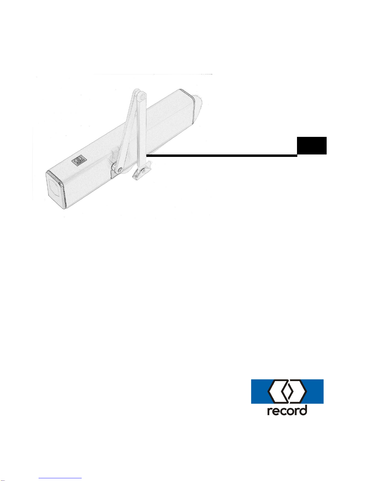
The recordDFA 127 swingdooroperatorhasbeen constructed inaccordancewith
the latest stateofthe art and the recognised technicalsafetyregulations, including
limitingofforcesand speeds. Nevertheless, dangercan ariseforthe userifnot
used asintended.
Installation, maintenanceand repairstothe recordDFA 127 must only
be performed byqualified and authorized personnel(technicians).
2.1 Use as intended
The DFA 127 swingdooroperatorisconstructed exclusivelyfornormalservice
withswingdoorsindryroomsand must be installed withinorinside buildings.
A different application oruseextendingbeyond thispurposeisnot considered use
forthe intended purpose. The manufacturerdeclinesall responsibilityforresulting
damage; the operatoralone shall bearthe associated risk.
Useforthe intended purposealsoincludesobservation ofthe operatingconditions
specified bythe manufacturer, includinguseand adjustment ofthe correct type of
arms, inaddition toregularmaintenanceand repair.
Unauthorised modificationstothe automaticdooroperatorexclude anyliabilityof
the manufacturerforresultingdamage.
2.2 General safetyand accident prevention regulations
Ingeneralno safetydevices(sensors)maybe dismantled orputoutof
service.
Duringthe learningcycle(whichmustonlybe performed bytrained per-
sonnel) the safetydevices(sensors)areswitched off!It mustbe en-
sured,therefore,beforeinitiatingthe learningcyclethatno personsor
objectsaresituated inthe dangerzone ofthe movingdoorleavesdur-
ingthe operation inordertoavoidinjuryordamage!
Noobjectsmust be placed inthe openingzone / pathofthe swingdoor
toavoidcrushingand shearingpoints!
The safeguardforcrushingand shearingstrainsat the side edgemust
be provided bythe manufacturer..

Page 4 of20 Rev. B11/2006 Operating instructionsDFA127 Full Power
3Technical Data
Dimensions: Operator600 x85 x124 mm (wxhxd)
Operatingvoltage: 230V∼
Powerconsumption: Standby13 W, rated power67 W
Max. torque: 50 Nm
Openingangle: Adjustablefrom70°to115°
Timedelay: Adjustablefrom0to20 seconds
Openingspeed: Adjustablefrom3to20 seconds
Closingspeed: Adjustablefrom5to20 seconds
Noiseemission -18 dB
Environmentconditions
Temperaturerange: -15 to+50°C
Humidityrange: Upto85%relativehumidity, non bedewing
3.1 Permissible doorleafweights and doorwidths
The curvesarecalculated usingtothe followingformula:
J=1/3 ×m ×b2
Standardarms: Jmax. 65 kgm2Key:
J=mass moment ofinertia[kgm2]
Slide arms : Jmax. 65 kgm2m=doorleafweight [kg]
b=doorleafwidth[m]

Operating instructionsDFA127 Full PowerRev. B11/2006 Page 5 of20
4 Construction and Function
4.1 Construction
Keytoillustration:
1 Mainsconnection terminals 9*Slide switchS1(rotatingdirection)
switch
2 Fine-wirefuse 10*
MultifunctionalswitchMFon STG
3 PowersupplyNET 11 Closingspring
4 Driveunit ATM 12 Vision paneladjust. springtension
5 Controlunit STG 13*
Adjustingscrewforspringtension
6 Connection terminalscontrolunit 14 Connectorsforarms(bothsides)
7 Motorprint MOT 15 StandardswitchBDI
8 ATE driveunit terminals 16 Statussignaland Reset button
*Donot changeanysettingsoradjustments! Theseoperationsarere-
served exclusivelyfortrained and authorized persons.
4.2 Components
The recordDFA 127 swingdooroperatorformspart ofan electromechanicalswing
doorsystemand comprisesthe followingmaincomponents:
Control unitSTG: Intelligent, learning, microprocessor-controlled control
system.
Driving unitATE: LowmaintenanceDC geared motorwithelectronicpath
measurement and integralthermostaticprotective
switch, gearboxwithadjustablespringtension.
PowersupplyNET: Compact 230 V powersupplywithintegralinput filter
and over-voltageprotection.
Control unitBDE: Asrequired withconvenient, simplemechanicalcontrol
unit and / oraprogrammableelectronicBDE-D.
1
3
2
12
4
5
7
15
6
11
13
14
10
9
8
16

Page 6 of20 Rev. B11/2006 Operating instructionsDFA127 Full Power
Construction and Function
Arm types: Powertransmission tothe doorleafbyuseofstandard
armpushingorslidingarmpulling/pushing.
Locking VRR (optional): It ispossibletoconnect an electricaldooropener
(24VDC) tothe operator.
Sensing units: Aestheticactuatingand self-monitoringsafetyelements
withadjustablesensitivityensureoptimum, smoothand
reliableoperation ofthe doorsystem.
4.3 Functional description
Inthe standard"Automatic"mode ofoperation the doorsystemopensbythe re-
sponseofan actuatingdevice(e.g. radarunit)topersonsorobjectsapproaching.
The doorclosesafterthe doorhold-open time, provided no furtheropeningpulse
isreceived.
Inthe "Lock"mode ofoperation, the doorisonlyopened byactuation ofan op-
tionalkey-operated contact (SSK). The doorclosesafterthe SSK doorhold-open
time, provided no furtheropeningpulseisreceived.
Anobstacletothe swingdoorleaveduring Closing leadstoan immediatere-
opening(reverse). The obstacleposition isrecorded inthe dooroperatorand this
position isapproached slowlywhen next closing. Anobstacletothe swingdoor
leafwhen Opening resultsinan immediatestop.

Operating instructionsDFA127 Full PowerRev. B11/2006 Page 7 of20
5 Operating instructions
5.1 Mech. control elements and indication
1MechanicBDI with3positions(controltoggleswitch)
2Reset button
3Statussignal
Mechanical BDI (control toggleswitch)
The followingoperationalmodescan be set up withthe 3-position toggleswitchon
the side cover:
Manual operation
Inthisoperation mode, the DFA works asanormaldoor-closer. It can easilybe
opened manually, and then closesautomatically. The connected actuatingele-
mentsareinactivated.
Automatic
The dooropensand closesautomatically, eitherbyactivation ofan actuatingele-
ment orbypushingwithactivated touchcontrol.
Continuouslyopen
The dooropensand remainsinthe open position. Ifan obstacleisencountered
whileopening, the DFA will attempt duringthe next fewsecondstoget the door
intothe set open position. Ifthe obstacleisstill present, the current position will be
accepted asthe continuouslyopen position.
1
2
3

Page 8 of20 Rev. B11/2006 Operating instructionsDFA127 Full Power
Operating instructions
The mechanicalBDI isbyfactorydefault alwaysconnected and activeon aDFA
127. Ifan additionalelectronicBDE-D isconnected, the operatingmode isset bya
defined prioritystructurefromthe BDE withthe highest priority.
The priorityand the code showninthe followingtableapplytothe operatingmode,
wherebyBDE2 (S2)and BDE1 (S1)represent the twoinput terminalsofthe control
unit (àJ7/1+J7/2, p.c.b. BDE-M) forthe mechanicalBDE:
(L=interruption or0V, H=+24V)
Mechanical BDI (toggleswitch) ElectronicBDE-D
BDE2 (S2) BDE1 (S1) Function Priority
(1=highest)
locked 1
one-way 2
L H continuouslyopen 3
H L manual 4
L L automatic 5
The BDE-D indicatesthe current operatingmode.
Ifan operatingmode isset on the BDE-D, whichhasno current priority, the status
message62 isdisplayed.
Reset button
Afterpushingforapprox. 5sec. anewstart ofthe control isperformed (software
reset). Afterthe reset the LEDlightsup permanently.
Statussignal
-Remainsoff ifno fault ispresent.
-Will blinkifafault ispresent (see statusand fault signals/ chapter8)
-Doeslight up permanentlyduringareset.

Operating instructionsDFA127 Full PowerRev. B11/2006 Page 9 of20
Operating instructions
5.2 Auxiliarycontrols on the control unitSTG127
General:
The CONTROLUNITSTG 127 operateswithactiveHIGHlevel, i.e. a+24 V level
must be applied toactivateafunction. Safetyinputsareactivated duringinterrup-
tions.
The signalground (0V)isconnected toprotectiveearth.
Jumpers:
J14:Master/ Slave
jumperat position M1formaster(factorysetting)
jumperat position S1forslave
J13:CANline termination
LED’s:
LD1:(red)controlLEDforpush-button operation (S1)
LD2: (green)+35V
Off forpowerfailure
LD3: (green)+24V
Lightsif+24V present.
Caution: inthe event ofapowerfailureprocessorreset takes
place1second afterthisLEDextinguishes.
Pushbutton S1
Thisisamultifunctionalswitchon controller(MF).
The useofthisswitchisreserved exclusivelyfortrained and authorized
persons.
Top viewofthe controlunit STG:

Page 10 of20 Rev. B11/2006 Operating instructionsDFA127 Full Power
Operating instructions
5.3 Functions of electronic controllerBDE-D (optional)
The electroniccontrollerBDE-D isan easilyop-
erated input and output deviceforthe control
and adjustment ofrecorddooroperators.
Logicallyarranged pushbuttonsallowan intuitive
operation and navigation throughthe operator-
specificmenu. The LCD withbacklight shows
dataand information about the doorstatuswith
symbolsand text messages.
Additionalinformation can be taken fromthe
manualofthe BDE-D (No. 903 109 271).
5.4 Operation modes
Automatic
Normalfunction
Tabletosignals(Xmarks areleasereaction)
CLOSED OPENING OPEN CLOSING
AKI x x x x
AKA x x x x
SSK x x x x
SIO x x x
SIS x x
TIPP x
One-waytraffic
Inone-waytrafficmode peoplecannot enterthe roomfromthe outside but they
can leaveit fromthe inside.
Tabletosignals(Xmarks areleasereaction)
CLOSED OPENING OPEN CLOSING
AKI x x x x
AKA* x x x
SSK x x x x
SIO x x x
SIS x x
TIPP
*AKA isactiveassafetydevicewhileclosing

Operating instructionsDFA127 Full PowerRev. B11/2006 Page 11 of20
Operating instructions
Manual operation
The doorcan be opened and closed byhand.
Opencontinuously
The doorisopened and staysopen.
Locked
Inthe operation mode Locked the lockingisactivated.
Tabletosignals(Xmarks areleasereaction)
CLOSED OPENING OPEN CLOSING
AKI x x x
AKA x x x
SSK x x x x
SIO x x x
SIS x x
TIPP
Reset
Afterpushingon the button forapprox. 5sec. thisstatusmessageon the
displayis:
No
Reset Operator?
Yes
Pushingagainon the button resetsthe operator.

Page 12 of20 Rev. B11/2006 Operating instructionsDFA127 Full Power
6 Configurations
6.1 ParameterOverview

Operating instructionsDFA127 Full PowerRev. B11/2006 Page 13 of20
Configurations
Configurationsofthe DFA 127 can onlybe made withthe electronicBDE-D. Ifa
toggleswitchisconnected, aBDE-D must be connected brieflyforthe configura-
tion.
Furtherinformation forparameterchangescan be taken fromthe usermanualof
the BDE-D (no. 903 109 271).
Pleasealwaysleavethe configuration reviewsheet inthe drive!
6.2 Parameterdescription
Parameter Setting
range Factory
default Description
DRIVING CYCLE
Closingspeed 0 -40
(5–20 s)
18 Slidercontrolwith40 steps
Openingspeed 0 -40
(3-20 s) 36 Slidercontrolwith40 steps
TIME DELAY
OPEN
Timedelayopen 0-40
(0-60 s) 2 EffectivewithAKA, AKI and pushto
actuate
0-20: Stepsof1s
21 -40:Stepsof2s
TimedelaySSK 0–40
(0-60 s) 4 EffectivewithSSK
0-20: Stepsof1s
21 -40:Stepsof2s
DRIVE
Openingangle 0 -40 35 The openingangleisestimated dur-
ingthe calibration run and isequiva-
lent tothe value of40.
6.3 Different factorydefaults fordoortypes LowEnergy
Parameter Factory
default Parameter Factory
default
DRIVING CYCLE
Closingspeed 10 Openingspeed 20

Page 14 of20 Rev. B11/2006 Operating instructionsDFA127 Full Power
7 Maintenance instructions
7.1 General
The recordDFA 127 swingdooroperatorisaproduct ofthe latest technology. It
hasbeen carefullymade and onlyleavesthe factoryfollowingthoroughtesting.
Automaticswingdoorsshouldbe operated and maintained toensuresafetyatall
times.
7.2 Care
The entireswingdoorsystemcan be cleaned withadampclothand commercially
availablecleaningagents. The cleaningagent must be harmonised tothe surface
whichhastobe cleaned.
It isrecommended toselect the "Continuouslyopen" or"Locked" mode ofoperation
forthispurpose, sothat the doordoesnot continuallyopen and closeunnecessar-
ily.
7.3 Maintenance, periodicinspection
It isrecommended tohaveatechnicalsafetytest withservicingperformed bya
specialist beforefirst commissioningand asrequired, but at least twiceayear.
Regulartestingand servicingbyourfullytrained personnelthereforeoffersthe best
guarantee foralongservicelifeand satisfactoryoperation. Wethereforerecom-
mend the signingofamaintenanceagreement. Ourservicedepartment will be
pleased tosubmit aproposal.
Ifnevertheless afault shouldoccur, whichyou cannot eliminate(see section 8)our
serviceorganisation orthe maintenancepersonnelofouragentsareavailable.
7.4 Service centres
InSwitzerland: Phone +41 (0)44 954 92 92 / Fax+41 (0)44 954 92 00
Alternativeservicecentre: _____________________________________________

Operating instructionsDFA127 Full PowerRev. B11/2006 Page 15 of20
8 Action incase of faults
8.1 Faultindication
Variousindicationsaregiven foran irregularityorfault dependingon the control
unit connected BDE-E orBDE-M.
Whenusing amechanical BDE (controltoggleswitch)
Withthe mechanicalcontrolunit it isnot possibletodisplayadetailed statussig-
nal. Ifafault occurs(will be shownbythe statussignalon the side cover), please
proceed accordingtosection 8.2.
Whenusing anelectronicBDE-D
General
Anycurrent operationalfaultsinthe drivesystemwill be displayed inthe Standard
screen. Ifseveralfaultsareactive, theywill be numbered: e.g. Fault 1/2
Incaseofan irregularitythe displaychangesautomaticallyfrommode ofoperation
leveltoerrordisplay. Every2secondsthe backlight changesbetween normal
/invers. Severalerrorscan be displayed (e.g. 1/2means: errorno. 1oftotal2er-
rors).
After10 secondsthe telephone numberofthe responsibleservicecentreisindi-
cated alternatingtothe fault indication. The failureindication and the phone num-
berchangeevery5seconds, whilethe inverseflashingisremaining. The de-
scribed sequenceappliestoall failures. However, previouslythe phone number
must havebeen given byan authorised specialised person.
Information about the drivesystem, suchasthe softwareversion, can be read out
bypressingthe key.
Afterpressingthiskeyonceagain, the phone numberofthe responsibleservice
centreand the last appeared fault indication isdisplayed inthe screen. Ifthe fault
messageconsistsofseverallinesthe first line will be displayed only.
Statussignalswitha"W"arewarnings. Forthesethe fault relaycontact output is
not connected. Elimination ofthe irregularityleadingtothe statussignalisper-
formed accordingtosection 8.2
Astatuscan usuallybe deleted bypressingthe keyfor5s(= Reset). Thispro-
ducesanewstart inthe controlunit.
If, however, the causeofthe fault hasnot been eliminated, the statusmessagewill
appearagainifthe fault occursagain.

Page 16 of20 Rev. B11/2006 Operating instructionsDFA127 Full Power
Action incase of faults
8.2 Errorelimination
The majorityoffaultscan be eliminated byconsultingthe followingtable. Ifthe
fault cannot be eliminated even afterworkingthroughthe table, pleasecontact the
servicecentre. Pleasealsocontact the servicecentredirectlywhen no recom-
mended action isspecified inthe table.
Status Symptom, fault,
doorbehaviour Cause Action
(consult service if no
recommend-action)
03 Door remainsopen Actuating device inside activelonger than
60 s
05 Door remainsopen Actuating device outside activelonger than
60 s
06 Door doesnot unlock Unlocking fault
23 Control unit SLAVE defective Reset byservice fitter
25 MASTER / SLAVE connection interrupted Reset byservice fitter
31 Door stops EMERGENCYSTOP button operated ReleaseEMERGENCY
STOP button
37 Door stops Faultymotor current
38 Door changestomanual
control Excess temperaturemotor Wait until motor has
cooled
39 Peripheral devices take
too muchpower Overload on +24 V supply Reset byservice fitter
41 Door stops Motor 1thermal sensor defective Reset byservice fitter
43 Door stops Incremental transmitter defective Reset byservice fitter
45 Minimumhold-open time
increased to20 secs. Motor current timeproduct too large Wait until motor has
cooled
46 Door stops Control unit defective Reset byservice fitter
47 Door remainsclosed SIOsensor longer activthan 60 sec. Removeobstaclefrom
surveillancerange of
sensor
50 Door stops Control unit defective Reset byservice fitter
52 Novalid driveparameter Initiatecalibration run
53 Door stops Interruption motor Reset byservice fitter
54 W Door joltspossiblywhile
opening Calibration run Initiate1opening cycle
59 Door stops SIS sensor longer activthan 60 sec. Removeobstaclefrom
surveillancerange of
sensor
60 Door stops Parameter memorydefectiveReset byservice fitter
61 Door remainsopen Keyoperated contact activelonger than 60
s Releasekeycontact
62 W Higher-order mode of
operation present Control unit BDE hasno priority Cancel higher-order
mode of operation

Operating instructionsDFA127 Full PowerRev. B11/2006 Page 17 of20
Status and fault signals
8.3 Detail description of status indications
General
A statuscan usuallybe deleted bypressingthe keyfor5s(= Reset). This
producesanewstart inthe controlunit.
If, however, the causeofthe fault hasnot been eliminated, the statusmessage
will appearagainifthe fault occursagain.
The followinglist containsthe causesoffaultsindecreasingpossibility. The fault
at the bottomofthe list hasthe smallest probabilitytooccurinthe controlunit
STG.
Status3: AKI sensor activelongerthan60 s
Automaticallyreset ifeverythingisinorder, orbyservicefitter
Status5: AKAsensor activelongerthan60 s
Automaticallyreset ifeverythingisinorder, orbyservicefitter
Status6: Unlocking error
Bolt possiblyjammed
Reset byservicefitter
Status9: “Opening” unsuccessful (after4collisions)
Check the interlock / removeobstacle
Reset throughservicefitter
Status11: Faultymotor current
Possiblyfaultywiringinprefabricated cables
Replacement byservicefitter
Status23: Slavecontrol unitdefective
Replacement byservicefitter
Status25: Slaveconnection (CAN) toMasterinterrupted
Clearbyservicefitter
Status31: EMERGENCYSTOP operated. Motor relayde-energises
Reset byresettingthe EMERGENCYSTOP button
Status37: Motor current
STG orATE defective
Reset byservicefitter
Status38: Overheatmotor
Manualcontroleffective
Doorleavespossiblytoo heavy, ortoo muchfriction
Reset bymotorcoolingdownorbyservicefitter

Page 18 of20 Rev. B11/2006 Operating instructionsDFA127 Full Power
Status and fault signals
Status39: Overloadon +24 V supply
Too manyexternalunitspossiblyconnected
Reset byservicefitter
Status41: Motor –temperaturesensor defective
Motorpossiblynot connected
Sensorinmotorpossiblydefectiveorcablebreakinsensorlead
Reset byservicefitter
Status43: Incremental encoderfault
Input cablepossiblynot connected orcablebreakinthe lead
Motorpossiblyblocked
Reset byservicefitter
Status45: Motor current–timeproducttohigh
Motorrelayde-energises
Manualcontroleffective
Automaticreset bymotorcoolingorbyservicefitter
Status46: Control unitSTG defective
Includesthe followingindividualfaults:
EPROM, RAM, Watchdog, Imax, ImaxT, differenceon SHE-EXT
Reset byservicefitter
Status47: SIO sensor activelongerthan60 s
Automaticallyreset ifinorder, orbyservicefitter
Status50: CPU2isdefective
Reset byservicefitter
Status51: Softwareversion
Softwareversion ofMasterand Slavedo not correspond toeach
other. Softwareupdatebyservicefitter
Status52: Norunning parameter
Start calibration run
Status53: Interruption motor
Possiblyno connection tomotor
Reset byservicefitter
Status54: Calibration run
Reset automatically
Status59: SIS sensor activelongerthan60 s
Automaticallyreset ifinorder, orbyservicefitter

Operating instructionsDFA127 Full PowerRev. B11/2006 Page 19 of20
Status and fault signals
Status60: Parametermemory(EEPROM) defective
Changecontrolunit
Reset byservicefitter
Status61: SSKactivelongerthan60 s
Automaticallyreset ifinorder, orbyservicefitter
Status62: BDE has no priority
Becauseahigher-levelsignalispresent
Automaticallyreset on releaseofBDE-button
Status72: Slaveconnection
Masterhasno connection toSlaveoperator
Reset byservicefitter
Status88: Difference parameter
The common parametersofM/S operatorsdo not correspond to
eachother.
Reset byservicefitter
Status89: Masterconnection
Slavehasno connection tomasteroperator
Reset byservicefitter
Status90: Railbeamactive>60 sec.
Automaticallyreset ifeverythingisinorder, orbyservicefitter
Status91: Bodyguard active>60 sec.
Automaticallyreset ifeverythingisinorder, orbyservicefitter
Status92: STG relaydefective
Replacement byservicefitter
Status93: Overvoltage24 V (from27V)
Status94: Spring calibration
Automaticreset
Status95: Error insense ofrotation
Status96: EEPROMvoid
Status99: Operator rotates
The greaseinthe gearwill be dispersed.
Automaticreset
Status105:Testbrake
Automaticreset

Page 20 of20 Rev. B11/2006 Operating instructionsDFA127 Full Power
Status and fault signals
Status106:Brake defective
Reset orreset byservicefitter
Status107:SIS defective
Asafetysensor(withtest input)inclosingdirection isdefective.
Reset byservicefitter
Status108:SIO defective
Asafetysensor(withtest input)inopeningdirection isdefective.
Reset byservicefitter
Status109:Factorysettings
Status110:Nomotor
Nomotordetection duringinitialisation (motortemperaturesensor).
Check motortemperaturesensor.
Reset orreset byservicefitter
Astatusnumberwitha"W"isawarning !!
Other manuals for DFA 127
4
Table of contents
Other Record Garage Door Opener manuals
Popular Garage Door Opener manuals by other brands

Chamberlain
Chamberlain Merlin MS65MYQ Installation and operating instructions

Ryobi
Ryobi GD200B Operator's manual

fadini
fadini MEC 200 LB instruction manual

Chamberlain
Chamberlain 7806CB Owner's instructions

Alutech
Alutech Levigato LG Series Assembly and operation manual

beamUP
beamUP BU250 product manual

Chamberlain
Chamberlain LiftMaster Security+ 2500DC owner's manual

vds
vds IBIS Technical installation manual

Safe Fleet
Safe Fleet R O M IV Series installation instructions

Smart Openers
Smart Openers Smart Lifter installation manual

RIB
RIB SUPER 2200 manual

Homentry
Homentry HESD01 Installation and operating instructions