DoorHan SLIDING-300 User manual

DRIVE
SLIDING-300/800
Installation and Operation Manual
3
4
5
5
9
9
9
OVERVIEW
SNOITUACERP YTEFAS
YLBMESSA EVIRD
INSTALLATION
NOITAREPO MSINAHCEM ESAELER
MAINTENANCE
TROUBLESHOOTING
© DoorHan, 2015

2
TABLE OF CONTENT
1. OVERVIEW . . . . . . . . . . . . . . . . . . . . . . . . . . . . . . . . . . . . . . . . . . . . . . . . . . . . . . . . . . 3
1.1. Main functions . . . . . . . . . . . . . . . . . . . . . . . . . . . . . . . . . . . . . . . . . . . . . . . . . . . . . . 3
1.2. Technical specifications . . . . . . . . . . . . . . . . . . . . . . . . . . . . . . . . . . . . . . . . . . . . . . . . . . 3
1.3. Complete set . . . . . . . . . . . . . . . . . . . . . . . . . . . . . . . . . . . . . . . . . . . . . . . . . . . . . . . 3
2. SAFETY PRECUTIONS . . . . . . . . . . . . . . . . . . . . . . . . . . . . . . . . . . . . . . . . . . . . . . . . . . . . . 4
3. DRIVE ASSEMBLY . . . . . . . . . . . . . . . . . . . . . . . . . . . . . . . . . . . . . . . . . . . . . . . . . . . . . . . 5
4. INSTALLATION . . . . . . . . . . . . . . . . . . . . . . . . . . . . . . . . . . . . . . . . . . . . . . . . . . . . . . . . 5
4.1. TOOLS . . . . . . . . . . . . . . . . . . . . . . . . . . . . . . . . . . . . . . . . . . . . . . . . . . . . . . . . . . 5
4.2. Drive installation and cabling diagram . . . . . . . . . . . . . . . . . . . . . . . . . . . . . . . . . . . . . . . . . . 5
4.3. Drive installation . . . . . . . . . . . . . . . . . . . . . . . . . . . . . . . . . . . . . . . . . . . . . . . . . . . . . 6
4.4. Installation of gear rack on DoorHan door . . . . . . . . . . . . . . . . . . . . . . . . . . . . . . . . . . . . . . . . 7
4.5. Installation of gear rack on third-party door . . . . . . . . . . . . . . . . . . . . . . . . . . . . . . . . . . . . . . . 8
4.6. Placement of limit switches plates . . . . . . . . . . . . . . . . . . . . . . . . . . . . . . . . . . . . . . . . . . . . 8
5. RELEASE MECHANISM . . . . . . . . . . . . . . . . . . . . . . . . . . . . . . . . . . . . . . . . . . . . . . . . . . . . 9
6. MAINTENANCE . . . . . . . . . . . . . . . . . . . . . . . . . . . . . . . . . . . . . . . . . . . . . . . . . . . . . . . . 9
7. TROUBLESHOOTING . . . . . . . . . . . . . . . . . . . . . . . . . . . . . . . . . . . . . . . . . . . . . . . . . . . . . 9

3
1. OVERVIEW
Sliding- 300/800 drive servies to automatic control of sliding doors without gate. It consists of a mechanical gearbox in oil
bath and an electric motor with integrated control unit. Both gearbox and motor are
made in a single package. The rotary movement of the output sprocket is converted into linear motion of door with a gear rack
fixed on the door.
External control button is connected to the control unit.
Self-locking gearbox provides door mechanical block, if the motor does not operate. In case of blackout, emergency manual
release mechanism allows to open and close the door manually.
1.1. Main functions
• Automatic stop system stops the motor quickly and reliably at the extreme positions.
• Stop at the extreme positions is carried out due to activation of contactless electronic limit switches.
• In case of blackout, rotation of the lever releases the drive, whereupon the door opening is possible by hand chain.
Drive control can be carried out in step-by-step mode (open-stop-close-stop) with fixed button or remote controller.
• Control unit is set inside the drive housing with a gear motor. The drive has a low noise level and overheating protection.
Sliding-300/800 automatic drive serves to operate sliding door. Do not use it for other purposes
1.2. Technical specifications
1.3. Complete set
The drive should be unpacked and inspected upon delivery to ensure the drive is free from damages. If any damages, please,
contact the supplier of the drive.
The parts included in the standard complete set of drives series Sliding are given in the following table.
OVERVIEW
Model Sliding-300 Sliding-800
Supply voltage, V/Hz 220-240/50
Capacity, W 130 280
Reduction ratio 1:32
Rack, mm M4 × 12.566
Gear wheel Z16
Maximal moment, Nm 7,5 20
Thermal protection, °C 125
Intensity, % 50
Operating temperature range, °C –20…+55
Protection class IP55
Max gate weight, kg 280 800
Gate speed, m/min 9 12
Control unit PCB-SL
Limit switches magnetic
Current consumption 2,1 A
Capacitor volume, mF 7 10
No. Description Quantity
1 Sliding-300/800 electric operator with built-in control unit 1 pc
2 Limit switches (open/close) 1 pair
3 Mounting base for concreting 1 pc
4 Fastening set 1 set
5 Release keys 2 pcs
6 Key-switch 1 pc
7 Rack (1 m) 4 pcs
8 Safety photocells 1 pair
9 Signal lamp 1 pc

4
2. SAFETY PRECAUTIONS
WARNING! Important safety instructions. Follow all instructions since incorrect installation can lead to
severe injury.
Follow any instructions of this manual as improper equipment installation could result in serious damage.
Sliding-300/800 drive serves to automatic control of sliding door. Use the drive as intended only, any misuse of
the drive is forbidden.
DoorHan is not responsible for any personal injury in case of the product misuse.
Prior to drive installation, make sure the door operates smoothly.
Installation shall be carried out according to the standards EN 12453 and EN 12445. These requirements shall be
complied with in countries outside the EU to ensure the required safety level.
Check if the door complies with standards EN 12604 and EN 12605 (see the door documentation).
These requirements shall be complied with in countries outside the EU to ensure the required safety level.
Mechanical joints of the door shall meet the requirements of standards EN 12604 and EN 12605.
Prior to drive installation, make sure the installation site complies with the drive specifications in climatic conditions.
Do not install the equipment in the premises with inflammables or any other hazardous environments, as this could
result in explosion or fire.
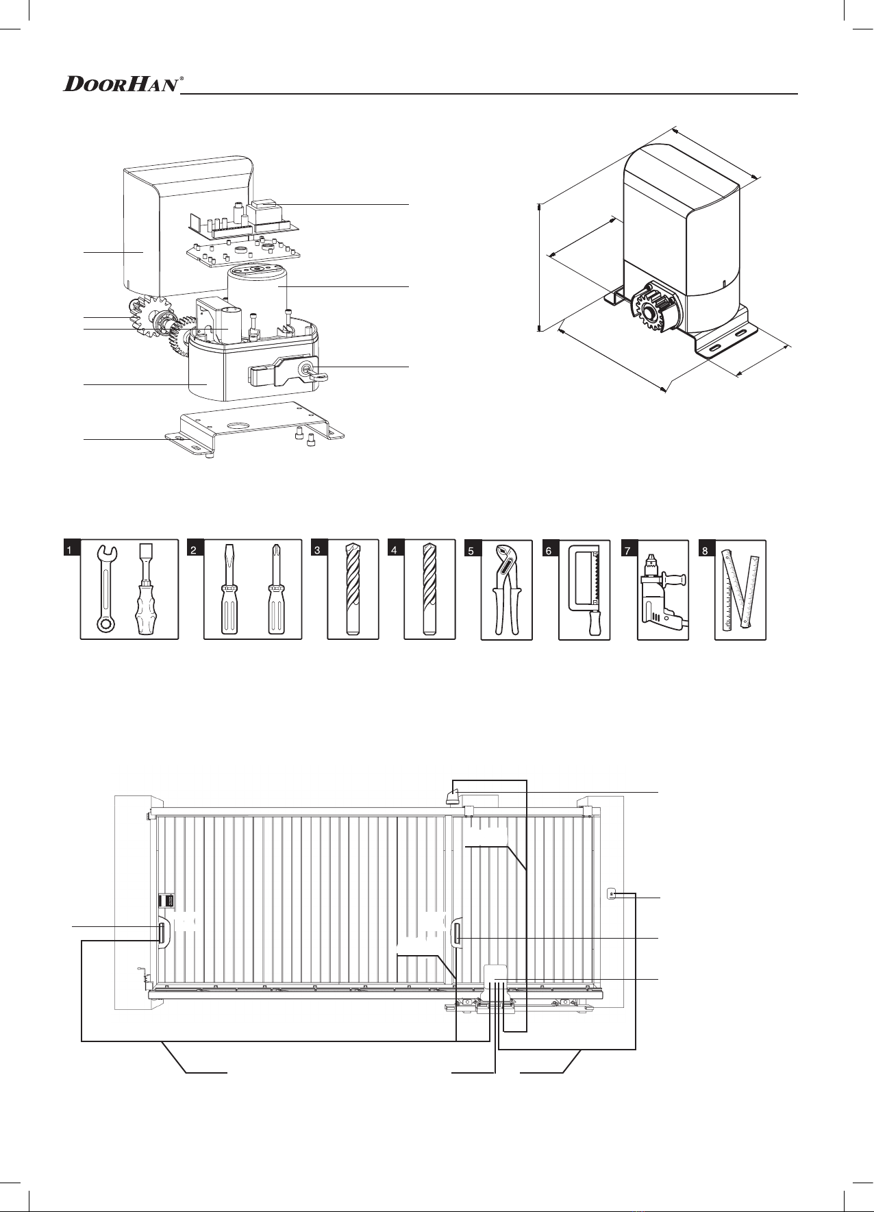
Use the tools specified in section “Tools” hereof during drive assembly, installation and adjustment.
Use a steady foot when working at height.
Use protective devices for your hands and face when drilling the holes.
Use the hardware supplied in a complete set of the drive or other appropriate hardware to fix the product.
It is necessary to disconnect the power supply during installation, cleaning or maintenance.
It is necessary to install an additional safety device to prevent the drive activation with an open gate when installing
the drive on a door with gate.
Use DoorHan original accessories, as third-party accessories can result in failure of automatic system.
DoorHan is not responsible for the unstable operation of automatic system when using third-party safety devices
and accessories without prior approval of DoorHan.
Do not leave the motors in released position. It can result in out-of-control door leaf movement and, as a consequence,
to is damage.
Do not drive, if the device requires repair or adjustment as defects in drive installation or improper installation of the
door can result in injury.
DoorHan bears no responsibility if the product is installed improperly and damaged during operation.
The drive is not equipped with a fixed power cord, so the power shall be supplied to automatic system through the
circuit breaker following at least 3 mm distance between adjacent contacts. It’s recommended to use a double-pole
circuit breaker of 10 A.
Make sure there are no obstacles in the drive operating area before its running.
Do not make any changes to the automatic system, not specified in this manual.
Remove the product package and dispose it. Do not leave the packaging materials within reach of children.
Never allow children to play in the door operating area during drive operation. Any remote controllers and fixed
buttons to operate the drive shall be prevented from possible use by children.
Drive and entry are permitted only at the door stopped and the drive turned off.
The content of this manual cannot serve as a basis for any claims.
The manufacturing company reserves the right to make changes in design and improve it without prior notice.
Frequently examine the installation, in particular check cables, springs and mountings for signs of wear, damage
or imbalance. Do not use if repair or adjustment is needed since a fault in the installation or an incorrectly balanced
door may cause injury;
Install any fixed control at a height of at least 1,5 m and within sight of the door but away from moving parts
Permanently fix the labels warning against entrapment in a prominent place or near any fixed controls
This appliance is not intended for use by persons (including children) with reduced physical, sensory or mental
capabilities, or lack of experience and knowledge, unless they have been given supervision or instruction concerning
use of the appliance by a person responsible for their safety
WARNING!
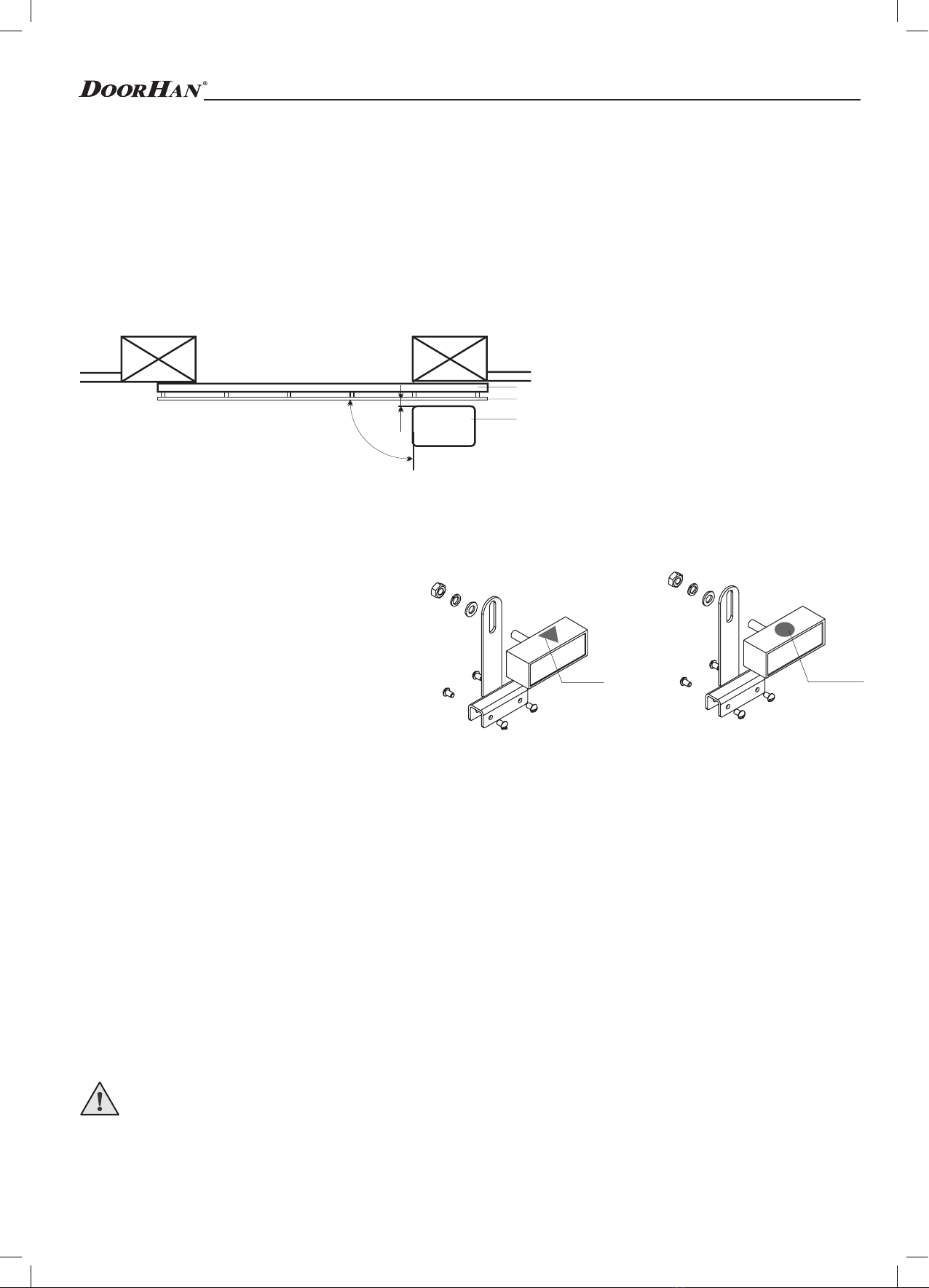
It’s required to install a mechanical stop to limit the stroke of the door leaf to ensure safe and proper
operation of the drive.
SAFETY PRECAUTIONS

5
3. DRIVE ASSEMBLY
синий красный
5
4
3
2
1
6
7
8
191
323
279
224
136
DRIVE ASSEMBLY
4.1. Tools
1. Set of wrenches
2. Set of flat blade and cross screwdrivers
3. Set of drill bits for metal
4. Set of drill bits for concrete
5. Pliers
6. Hacksaw
7. Electric drill
8. Tape rule (folding rule)
1. Gearbox housing
2. Housing cover
3. Control unit
4. Stator
5. Capacitor
6. Terminal block
7. Gear
8. Drive mounting
9. Mounting cover
10. Release mechanism
11. Limit switches
4. INSTALLATION
4.2. Drive installation and cabling diagram
1. Drive with control unit
2. Photocells
3. Warning light
4. Key button
2
3
2
4
1
2Х0,5
2Х1,5
2Х0,53Х1,5
4Х0,5
TX RX

6
DRIVE ASSEMBLY
5 макс
49
40
15–32
112
Z16
WARNING! Remove the breather screw after installing the drive.
Materials to install Sliding-300/800 and related accessories (if any):
ycable 2 × 0,5 mm2 (photocells transmitter, step-by-step control button);
ycable 4 × 0,5 mm2 (photocells receiver);
ycable 3 × 1,5 mm2 (power supply);
yuse cables with appropriate voltage insulation.
WARNING! ELECTRIC SHOCK HAZARD!
Cables of 220-240 V AC shall be installed by a qualified specialist. Cabling is carried out with protective channels, do
not allow cables and moving door elements contact. If the supply cable is damaged, it should be replaced by a related cable
Зубчатая рейка
Уровень земли
Шестеренка
2–3 мм
4.3. Drive installation
Follow these rules to ensure safe and efficient operation of the drive:
yDoor design shall provide the installation of automatic equipment.
ySoil shall be sufficiently firm and stable to mount the installation base for the drive.
yFoundation area shall be free from pipes or electrical cables.
yIf the motor is not protected from passing transport, install the appropriate protection means to prevent from accidental
impact.
yMake sure of effective drive grounding.
1. Mount the drive on the base and set the desired distance between the drive gear and door by moving it. Secure the drive.
2. Release the drive.
3. Put protective cable tubes or channels through the holes in the base.
4. Attach the gear racks to the door horizontally (see pp. 4.4 or 4.5).
5. Set the desired gap between the gear rack and drive gear (~ 2 mm). The gear teeth shall be geared with the rack teeth along
the full width.
6. Move the door and make sure the gear rack does not put pressure on the gear and does not shift. Secure other rack sections.
7. Open the door and set the limit switch to open (see p. 4.6).
8. Close the door and set the limit switch to close (see p. 4.6).
9. Put the drive in gear.
10. Adjust the control unit (see p. 5).
11. Perform a test run and make sure of normal operation of the drive.
12. If necessary, adjust the position of the limit switches.
max 5
10

7
4.4. Installation of gear rack on DoorHan door
In case of drive installation on DoorHan sliding door, gear rack mounting shall be carried out as follows:
Зубчатая рейка
Уровень земли
Шестеренка
2–3 мм
1. Install C-profile (1) on leaf mounting brackets (2) and secure
it with self-tapping screws (see figure 1).
Figure 1
2. Get round head bolt (3) and cover plate (4) into C-profile (1)
(see figure 2).
3. Apply clamp (5) over C-profile so that the bolt gets
through the clamp opening (see figure 3).
4. Screw the collar (6) on the bolt, but do not tighten it. Collar
(6) shall press the clamp (5) to C-profile (1) (see figure 4).
5. Repeat steps 2-4 for other mounting assemblies. Their total number shall match the one of holes in the gear racks.
6. Place the resulting mounting assembly opposite to the
hole in gear rack (7) (see figure 5).
7. Secure gear racks on mounting assemblies with bolts (8)
(see figure 6).
8. Align the teeth of all thesection elements using free
rack (see figure 7).
9. Tighten the mounting assemblies.
Figure 2
Figure 3 Figure 4
Figure 5 Figure 6
Figure 7
Figure 8
2
1
4
13
56
1
5
7
8
Зубчатая рейка
Уровень земли
Шестеренка
2–3 мм
Ground level Gear
Gear rack
Gear rack
mm
DRIVE ASSEMBLY

синий красный
4.6. Placement of limit switches plates
Sliding-300/800 drive is equipped with ferreed
contacts (magnetic reed switches) that are responsive
to the movement of magnet attached to the rack and
generate a command to stop the door.
Install the limit magnets as follows.
1. Release the drive (see sec. “Release mechanism
operation”).
2. Move the door manually to the opened position with
2-5 cm to the mechanical stop
3. Move the magnet of limit switch to open (triangular blue sticker) along the rack in the direction of door opening until magnetic
reed switch is OFF. This can be seen by looking at the corresponding LED on the control board (see sec. “Control unit LEDs”).
Slide the magnet in the same direction for approximately 2-3 cm and secure it to the rack.
4. Move the door to the closed position with 2-5 cm to the mechanical stop.
5. Move the magnet of limit switch to close (round red sticker) along the rack in the direction of door closing until magnetic reed
switch is OFF. This can be seen at the appropriate LED on the control board (see sec. “Control unit LEDs”). Slide the magnet
in the same direction for approximately 2-3 cm and secure it to the rack.
6. Move the door to the middle position and lock the drive (see sec. “Release mechanism operation”).
7. Provide at least 2 cm gap from the door to the mechanical stop in the extreme opened and closed positions to ensure quality
operation of the system.
8. Run several complete cycles of operation and verify the installation of limit switches. The drive shall stop upon reaching the
limit switch with the corresponding LED goes out. SW1— LED for switch to close. SE2 — LED for switch to open.
9. Distance from the limit switch to limit switch magnet shall be not more than 5 mm.
WARNING! Upon adjustment of limit positions, make sure of normal operation of limit switches: the corresponding LED
on the control unit shall go out upon response. If the light does not go out, repeat the adjustment.
8
Installation notes for the rack
1. Never weld the racks to the collars or to each other.
2. Check that the door can reach mechanical stops, and there is no friction while moving the door.
3. Do not lubricate any rack or gear.
4.5. Installation of gear rack on third-party door
1. Move the leaf manually in one of its extreme positions.
2. Put the first part of the rack on the gear and install the collar between the rack and the door so that they coincide with the
upper part of the slot.
3. Mark the drilling point on the door. Drill a hole of 6.5 mm and cut the thread using a tap M8. Tighten the bolt.
4. Move the leaf manually so that the rack remains on the gear and repeat step 3.
5. Attach another rack element against the previous one. Align the teeth of these two elements using free rack. Move the door
manually and perform all operations in the same way as for the first element. Repeated as long as the door is not completely
overlapped by racks.
90
23
Полотно ворот
Зубчатая рейка
Монтажное основание
Limit switch to closeLimit switch to open
Door leaf
Gear rack
Installation base
blue red
DRIVE ASSEMBLY

9
6. MAINTENANCE
Sliding-300/800 automatic system does not require any special maintenance.
• Only qualified specialists trained in DoorHan authorized centre can carry out repair and maintenance.
• The installer shall present the user how to unlock the door in case of emergency and deliver information on maintenance
and operation of the automatic system after its installation.
• Use DoorHan original spare parts during maintenance.
• Check DoorHan automatic system for problems at least once per 6 months.
• Check the smooth movement of the door under automatic control regularly.
• Check the correct installation of extreme positions, operation of safety devices regularly.
• When power is off, the door stops. After power is on, the drive can be controlled under normal mode.
• Deliver the product to a special recycling center upon expiration of its service life!
• If you lose this manual, you can request a duplicate by sending a letter to: Kralovsky VRCH 2018, Kadan, 43201, Czech
Republic or e-mail to: [email protected].
• The manufacturer (DoorHan) does not exercise direct control over the door and automatic equipment installation, their
maintenance and operation and can not be responsible for the safety of the door and automatic equipment installation,
operation and maintenance.
5. RELEASE MECHANISM OPERATION
Use the lever of embedded release mechanism to release the drive. When re-
leased, the door may be opened and closed manually.
If it’s necessary to open the door manually when power is off or drive fails, use
the release mechanism:
1. Insert the key into the lock (Fig. 1).
2. Turn the key clockwise.
3. Without taking the key out, pull the lever of the release mechanism (Fig. 2).
4. Turn the key counterclockwise and remove the key from the lock.
5. Move the door manually.
Back to normal operation of system
To prevent from automatic push upon the door activation, power off the system
before locking the drive.
1. Insert the key into the lock.
2. Turn the key counterclockwise.
3. Without taking the key out, push the lever of the release mechanism against
stop.
4. Turn the key clockwise and remove the key from the lock.
5. Move the door manually until the drive is locked.
7. TROUBLESHOOTING
Malfunction Potential reason Remedy
Drive does not operate
Disabled power or absence of power Make sure of power
Obstacle in door movement Remove the obstacle
Bad wiring connections Check the wiring connections
The door does not move after use of
release mechanism Drive is in ungeared position Put the drive in gear
Drive stops suddenly
Drive thermal protection is activated Let the drive cool
Improper adjustment of limit switches or operating
time
Adjust the position of limit switches and adjust the
operating time
The door does not open or close to the full Improper adjustment of limit switches Adjust the limit switches
Force protection is activated Adjust the drive force
RELEASE MECHANISM OPERATION
1
2

NOTES

NOTES

Weverymuch appreciate that you havechosen the productmanufactured by our
companyand believe that you will be satisfied withits quality.
For information on purchasing, distribution and servicing contact
DoorHan central office at:
116/2+3A, Wawanje-Panvel Road, Taloja MIDC (E), Mumbai, India
Zip code -410208
Telephone: +91(22)-653-123-44
www.doorhan.in
This manual suits for next models
1
Table of contents
Other DoorHan Garage Door Opener manuals

DoorHan
DoorHan HYBRID 02 User manual

DoorHan
DoorHan SHAFT-30 User manual

DoorHan
DoorHan SLIDING-1300 User manual

DoorHan
DoorHan YETT 01 User manual

DoorHan
DoorHan YETT 02 User manual

DoorHan
DoorHan RSD01 User manual

DoorHan
DoorHan SLIDING-1300 User manual

DoorHan
DoorHan RSD01S Series Product guide

DoorHan
DoorHan ISD01 Series Manual
Popular Garage Door Opener manuals by other brands

SOMFY
SOMFY Dexxo Pro Commissioning instructions

tau
tau 650ESE installation guide

Lear
Lear Car2U user manual

Letron Auto Gates
Letron Auto Gates SL810 User's installation guide

Roma
Roma Rolento B1/55 Assembly instruction

Roger Technology
Roger Technology H30/645 INSTRUCTIONS AND RECOMMENDATIONS FOR THE INSTALLER