Record CG3 User manual

Document Version: 1.33
Date: Feb. 04/ 2019
RECORD TECHNOLOGIES INC.
Part people. Part Technology.Completely at Your Service.
RecordCG3User
Guide

R E C O R D T E C H N O L O G I E S I N C .
CG3 Taximeter User’s Guide
Record Technologies Inc.
505 –53 Ave., S.E.
Calgary, AB, Canada T2H-0N5
Phone 1.800.661.1649 • Fax 403.255.4953

Table of Content
Thank You................................................................................1
How to use this manual............................................................2
1.0 CG3 Components..............................................................2
1.1 A Note Concerning the RS-232 Cable Connector.............3
2.0 Wiring..............................................................................4
2.1 Grounding ...........................................................................4
2.2 Vehicle Speed Signal (VSS) ...............................................5
2.3 DC Power Requirements ....................................................6
2.4 Fusing.................................................................................6
2.5 Relays.................................................................................6
3.0 CG3 User Interface .............................................................7
3.1 Config Switch ......................................................................7
4.0 CG3 Modes.....................................................................9
4.1 Vacant Mode....................................................................10
4.1.2 Displaying Time and Date.................................................11
4.2 Hired Mode.......................................................................12
4.2.1 Starting a Fare..................................................................12
4.2.2 Incrementing Extra Charges.............................................13
4.2.3 Toggling Rate time-charges Off / On................................14
4.2.4 Ending the Fare................................................................14
4.3 End-of-Fare Mode............................................................15
4.4 Configuration Mode...........................................................17
4.4.1 Configuration Menu...........................................................18
4.4.2 Set Rates Mode................................................................20
4.4.3 Calculating Drop Distances..............................................20
4.4.4 Programming Rates..........................................................21
4.4.5 Calibrating Mileage...........................................................23
4.4.7 Set the Signal-Conditioner Value (VSS Sensitivity), F2....24
4.4.8 View / Manually Set Calibration Value..............................25
4.4.9 Calibration Procedure.......................................................26
4.4.10 Adjusting the Sensitivity during Calibration Test ...............26

4.5 Setting up the CG3 OBDII Interface..................................27
4.5.1 OBDII Settings Menu .......................................................30
4.5.2 Explanation of OBDII menu options.................................30
4.6 Loading Rates from a USB drive......................................32
4.6.1 Attaching a USB flash drive to the CG3...........................32
4.7 Configuring Dispatch Communication..............................34
4.8 Setting the Security Code.................................................36
5.0 Main Menu....................................................................37
5.1 Viewing Shift and Total Stats ...........................................38
5.2 Upload Trip Statistics to USB Flash Drive........................39
5.2.1 Uploading Trip data to USB flash drive............................41
5.2.2 Printing Daily Trip Data....................................................41
5.3 Procedure for clearing the daily trips................................42
5.4 Setting the Clock..............................................................43
5.5 Setting the Date ...............................................................44
5.6 Display Test .....................................................................45
5.7 View Rates.......................................................................45
5.8 View Calibration...............................................................46
5.9 Reset Bluetooth................................................................46
6.0 Audit Mode.......................................................................47
7.0 Printing............................................................................. 49
7.1 Printer Setup....................................................................50
7.2 Explanation of Printer Menu Options................................51
7.3 Creating the Receipt Header file......................................53
7.3 Printing Receipts..............................................................53
7.3.1 Printing with Bluetooth Printers........................................54
Appendix 1.0..........................................................................55
RATES.csv format.........................................................................55
Example Trip File..........................................................................57
Document Version: 1.32................................................................57

C G 3 U S E R ’ S G U I D E
1
Thank You.
We appreciate your business, and have made every
effort possible in designing this manual to be a helpful
resource in getting you on the road as quickly as
possible.
E have developed the Record CG3 taximeter with YOU in mind. After
many years of research and development, we are confident that you will be
pleased with the features and reliability of this product.
CG3 Features:
Integrated USB On-the-Go (host and device capability).
Can read and write to and from off-the-shelf USB flash drives.
Integrated Bluetooth wireless communication.
RS-232 serial communication.
Printer capability, compatible with multiple third-party manufacturers.
Security-locked trip statistics.
Auto-brightness adjustment for longer display life.
128 / 256 AES Standard encryption / decryption capable.
Stores detailed information for the last 1000 trips.
Upload trip statistics to USB flash drive in .csv format.
Internal diagnostics that ensure reliable, uninterrupted operation.
Quickly set rates from USB flash drive or Bluetooth.
Upgdate the firmware directly from a USB flash drive.
Integrated pulse-divider and signal filter for accurately measuring
distance.
Internal solid-state relay (switch) for controlling roof-light.
Introduction
W

2
Internal short-circuit and surge protection.
Multiple communication protocols for communicating with third-party
dispatch systems or our freely available Android app.
How to use this manual
We encourage you to first skim through this guide so that you can familiarize yourself
with the content. Then, carefully read through the sections that are specific to your
requirements.
1.0 CG3 Components
Figure 1
The CG3 consists of the following components, as shown in Figure 1:
1. CG3 taximeter display unit.
2. Cable and bracket assembly, with attached RS-232 serial cable and connector
(see Figure 2 below).
3. Seal-screw and hex-nut.
4. (Optional) USB mini-B adaptor.
1
2
3
4

3
Figure 2: D9 Serial Connector. Used for RS-232 communication.
1.1 A Note Concerning the RS-232 Cable Connector
In Figure 2, the connector shown above is a female connector which is used with
many third-party dispatch terminals, and was the original default option provided
with early models of the Record CG3. Nowadays, the CG3 comes with a male
connector by default for communicating with the BlackCat OBDII device for
measuring automobile speed.
If you require a female connector, please contact us for a male-to-female adaptor,
which we provide for a nominal cost, plus shipping.

4
2.0 Wiring
RED Battery +12V
BLACK Ground
GREEN Ignition (top-light power source)
BROWN Roof-light (top-light power output)
WHITE Vehicle Motion
2.1 Grounding
We recommend that you ground the CG3 taximeter at the automotive battery, in order
to:
properly detect the vehicle motion signal, and
to aid in ensuring that vehicle noise is not induced into the taximeter
motion circuit (from nearby circuits, motors, etc.).
This can’t be over emphasized. In our experience, 90% of problems having to do
with detecting motion signals and/or noise are directly attributable to where
the taximeter is grounded. Grounding the taximeter to the frame, body or some
other intermediary point raises the potential for two main difficulties:
1) By introducing a small, but significant circuit resistance at the motion
detection circuit within the taximeter. This interferes with the capability of
the taximeter to detect a signal that is often already low in voltage
strength.
1
2) By creating ground loop problems, which are essentially circuits of
electromagnetic signals (noise). By grounding the taximeter to an
intermediary point, you risk having the taximeter act as a path to ground
for this noise.
On the other hand, Grounding at the battery helps to isolate the taximeter from noise,
by ensuring that it is not sharing a ground with other circuits. By grounding the
1
We have even encountered occasions where this small resistance produces voltage, which in turn generates current, which can then
flow back into the vehicle speed sensor, causing all sorts of problems such as improper automobile transmission shifting.

5
taximeter to the car battery, you effectively eliminate possible problems from
installation onward.
2
.
Finally, while the taximeter does provide filtering of noise signals (see section’s 4.4.6,
4.4.7 and 4.4.10 for more information), it is our experience that grounding to the
battery is your best protection against noise being interpreted as motion signals, and
ensuring that the proper motion signal is detected.
If by chance, you still encounter noise issues with your installation (i.e. the taximeter
registers distance while the vehicle is stationary) we have an inexpensive signal
conditioner device that will help you clean up and/or detect very weak signals. If this
is something that you require, you may call us or go to our website to purchase the
device:
http://recordtechnologies.com/collections/taximeters/products/signal-conditioner
Figure A: Record Signal conditioner that helps eliminate noise issues when reading VSS pulses. Can also
be used to help detect weak signals.
2.2 Vehicle Speed Signal (VSS)
The CG3 will detect motion signals with the following minimum strength:
1) Analog (sine-wave): 700 mV peak-to-peak
2
Often, where the taximeter has been grounded to the frame or body, the taximeter will appear to operate fine in
the early going, but as time goes on, mileage-detection deteriorates.

6
2) Digital (square-wave): 300 mV peak-to-peak
Also, the taximeter will detect signals with frequencies up to 15 kHz (15,000 cycles,
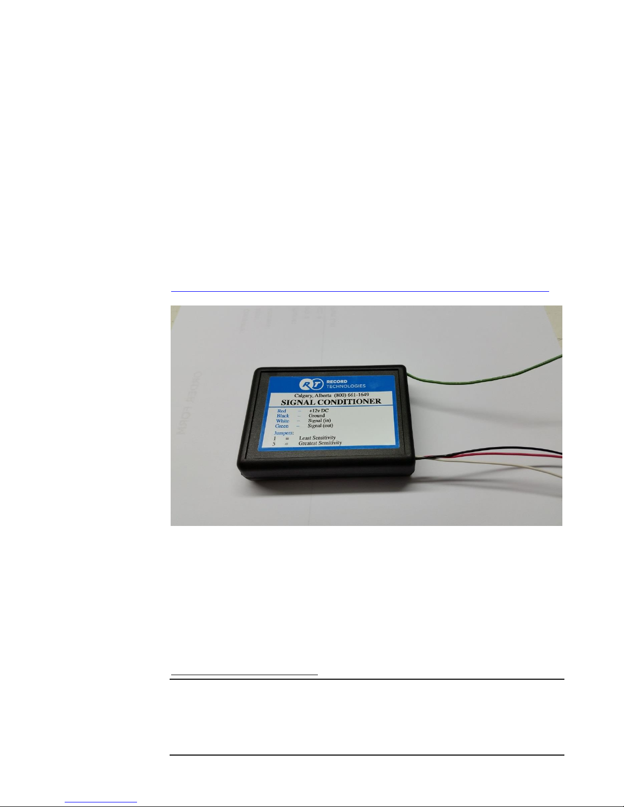
or, pulses per second). Signals that are weaker than the parameters above can still be
detected with the help of our Signal Conditioner (see above).
2.3 DC Power Requirements
The Record CG3 requires a minimum of +5 Volts DC to operate. Further, the built in
voltage-regulator and surge-suppression will ensure that over-voltage or over-current
conditions will not interrupt its operation.
2.4 Fusing
As mentioned above, the taximeter has a built in power regulation. However, we
recommend that you still provide in-line fusing for the roof-light circuit, as the
taximeter does not provide protection. For bulbs, you should use a 3 Amp in-line
fuse, connected between the ignition/accessory power and the CG3 Green
wire. For LED top-lights a maximum of 1 Amp fusing should be used.
2.5 Relays
Internally, the Record CG3 has a large transistor sufficient to switch bulb or LED roof
lights without issue, and provides sufficient protection for the taximeter with regards to
large surges in electrical current. However, we see in odd occasions where, despite our
best efforts and recommendations, the internal transistor is somehow damaged and no
longer able to switch the roof light state. This results in downtime for the user where
they are required to send us the taximeter for repair.
To eliminate this possibility from happening, we recommend using an external relay for
switching the roof light circuit, particularly when using bulbs.
Further, some customers require compatibility with third-party dispatch systems that
require a +12Vdc signal to be provided externally whenever the taximeter is in the
HIRED state. Such configurations will require a SPDT type relay for providing a
signal which is inverse to the state of the roof light (which is off when the taximeter is
HIRED).
In either case, a good candidate relay is the Cole-Hersee RC-400112-NN, which can
be purchased either from us or from multiple third-party dealers.

7
3.0 CG3 User Interface
The CG3 has been designed with user-friendliness in mind. The buttons have been
labeled with descriptive icons and text to help provide an intuitive interface, which is
intended to help you get familiar with its use quickly. See figure 3 below for a brief
guide to the user interface.
Figure 3
Config Switch Time Button Rate Button Extra Button Fare Button Light Sensor
The text above the buttons refer to the roles that the buttons play primarily while a
fare is in operation (Hired Mode), and the colored icons (arrows and star /asterisk)
refer to functions that the buttons provide in all other modes, which is mainly to select
and adjust values, and to scroll various menus.
3.1 Config Switch
The Config Switch, or hidden lock, refers to two copper-plated holes located on the
circuit-board, which are accessible through the two small, parallel holes in the
hexagonal indent (see Figure 4 below). The Config Switch is used to enter
Configuration Mode.

8
Figure 4: Config Switch. Note the two copper plated holes on the underlying circuit board.
To activate the Config Switch, you have to short (i.e. electrically connect) the two
plated holes together. This can be done, either with a rate-set pin (these are usually
provided with CG3 upon purchase), or simply with a stiff piece of wire (we find that a
stretched out paper-clip works the best). See Figures 5 and 6.
If nothing happens, gently wiggle the rate-set pin until Configuration Mode is entered.
The CG3 will display “RATES” when you have successfully done so.
Figure 5: Activating the Config Switch, using the rate-set pin. Contact must be made with the two copper-plated holes on the circuit-
board inside the taximeter case, in order to short the holes together.

9
Figure 6: Using a simple length of wire to activate the Config Switch. A paper-clip works best because of the inherent stiffness or
rigidity.
4.0 CG3 Modes
There are 4 main CG3 Taximeter Modes:
1. Vacant Mode: The taximeter is idle, and simply waits for user input. From
here, the user can: 1) start a fare i.e. enter Hired Mode, 2) enter
Configuration Mode in order to configure the meter rates, mileage and
dispatch settings, or 3) access the Main Menu.
2. Hired Mode: The mode while the taximeter is running a fare.
3. End-of-Fare: The active mode when a fare has been completed. User can
display net total and separated tax.
4. Configuration Mode: The mode where the taximeter rates, mileage,
communication (RS-232 and Bluetooth), dispatch type, and Security code are
set. You may only enter this mode by activating the Config Switch (section
3.1).

10
4.1 Vacant Mode
This is the state that the taximeter starts in when first turned on. The “VACANT”
indicator will be on, and the $Extra and $Fare displays will be blank. Also, the rate
LED will be on to indicate which rate is active.
Figure 7 : VACANT MODE Currently active rate
The user can now select one of several available actions, by pressing one of the four
buttons:
Table 1: Vacant Mode Button Functions
Button:
Action:
Fare
Start a Fare. Enters Hired Mode.
Extra
Display Time and Date.
Rate
Change the current Rate.
Time
Enter the Main Menu.

11
4.1.2 Displaying Time and Date
While in Vacant Mode, you can
display the current time by
pressing the Extra Button.
In the Fare display, the format
displayed is Hour - Minute.
The display on the left-hand side
indicates the AM/PM/24 Hour
clock mode.
Pressing the Extra a second time
will display the date, with the
following format: Year - Month :
Day.
Pressing the Extra Button a third time exits back to Vacant Mode.

12
4.2 Hired Mode
Figure 8: Entering Hired Mode by pressing the Fare Button.
4.2.1 Starting a Fare
When the CG3 is in Vacant Mode, pressing the Fare button will start a fare and turn
on Hired Mode. The HIRED indicator on the right-hand side of the taximeter will
illuminate to display the current state.
Table 2 describes the taximeter responses to each button press:
Table 2: Hired Mode Button Operation
Button:
Actions:
Fare
Stop the Fare. This can only occur if the time
charges are first turned off (see below).
Extra
Increment a single Extra Charge. If the
maximum is exceeded, the accumulated Extra
charges will roll-back to $0.00.
Rate
None.
Time
Toggle Time Charges off / on. When time
charges are off, the taximeter will only charge the
distance rate.

13
4.2.2 Incrementing Extra Charges
Pressing the Extra Button will increment a
single extra charge. In this case, the Extra
charge has been pre-set to $2.22.
Repeatedly pressing the Extra Button will
increment the Extra Charge, up to a pre-
set maximum (this is described in
Configuration Mode).
In this example, the Maximum Allowable
Extra Charges is set to $8.88.
If the maximum allowed Extras would
otherwise be exceeded by additional
accumulations, the Extra Charges will
return to $0.00 (this is handy if you
accidentally increment the Extras beyond
what you intended).

14
4.2.3 Toggling Rate time-charges Off / On
Pressing the
Time Button will Turn
off the time charge.
The taximeter will then
only charge by distance.
When the rate time
charge is OFF, the
TIME OFF indicator
will illuminate.
Pressing the Time
Button again will turn
the rate time-charges
back on.
4.2.4 Ending the Fare
To stop the fare, the rate-time charges must first be turned off (see above). Pressing the
Fare Button will then stop the fare, and enter End-of-Fare Mode.
The taximeter will briefly display
the fare total (Fare + Extras) for 3
seconds.
Figure 9: Turning off time-charges.
Figure 10:Fare is stopped by pressing the Fare Button, while time-charges
are off. Note the "TOT" indicator in the Extra display, indicating the total
fare (Fare + Extras) is currently displayed in the Fare display.

15
4.3 End-of-Fare Mode
After the Fare + Extras
total have been displayed for 3
seconds, the taximeter will display
the separated Fare and Extras.
This state will remain displayed until
you press the Fare button.
Alternatively, you have the option of
displaying the split-out tax percentage of the
total, by pressing the Time Button.
After 1.5 seconds, the Fare minus the
tax will be automatically displayed
briefly.
(You may repeat this sequence
indefinitely).

16
The taximeter will then return to the
state where the Fare and Extras are
displayed separate.
To re-display the total, press the Extra
Button. This too can be repeated
indefinitely.
To exit End-of-Fare mode, press the Fare button. This will return the taximeter to
Vacant Mode.
Other manuals for CG3
1
Table of contents
Other Record Measuring Instrument manuals