Record CG3 Manual

1
CG3 Setup Instructions
Figure 1
The CG3 consists of the following components:
1. CG3 taximeter display unit.
2. Cable-and-bracket assembly, with attached RS-232 Serial communication cable.
3. Seal-screw and hex-nut.
4. (Optional) USB mini-B adaptor.
Figure 2: D9 Serial Connector. Used for RS-232 communication. You will need a male 9-pin
Connector if you are using a Black Cat adapter for sensing motion, or a female connector if you are
communicating with most Dispatch Terminals (MDT). IMPORTANT: See section 2.2
1
2
3
4

2
2.0 Wiring: Main Cable Harness
RED Battery +12V
BLACK Ground
GREEN Ignition (roof-light power input)
BROWN Roof-light (roof-light power output)
WHITE Vehicle Motion (VSS)
2.1 Fusing
IMPORTANT: While the CG3 Taximeter does contain internal protection
against most catastrophic high-current instances, some precautions still need to
be taken by the operator to protect the CG3 Taximeter roof light circuit against
unforeseen extreme current surges that can occur in the often hostile automotive
environment (with regards to sensitive electronics).
Add an in-line fuse, connected between the ignition/accessory power and the
CG3 Green wire.
Fuse size:
1) For roof-lights that use incandescent bulbs: use a 3 Amp in-line fuse
2) For roof-lights that use LED strips: use a 1 Amp in-line fuse.
FOR THE BEST PROTECTION WHEN USING BULB ROOF-LIGHTS:
due to the higher current requirements, we also recommend using an external
mechanical relay, with the input of the relay connected to the Brown wire, and
the output connected to the roof-light.
NOTE: It is your responsibility to ensure adequate protection is provided on this
circuit, as too large of a fuse -- or no fuse at all -- can result in damage to the
internal circuitry of the taximeter, which unfortunately cannot be covered by
warranty.

3
3.0 How to Enter Programming Mode
The Config Switch refers to two copper-plated holes located on the circuit-board,
which are accessible through the two small, parallel holes in the hexagonal indent (see
Figure 4 below).
Figure 3: Config Switch. Note the two copper plated holes on the underlying circuit board.
To activate the Config Switch, you have to short the two plated holes together. This can
be done, either with a programming pin (these are usually provided with CG3 upon
purchase), or simply with a piece of wire (we find that a paper-clip works the best).
Figure 4: Activating the Config Switch, using the rate-set pin. Contact must be made with the two copper-plated
holes on the circuit-board inside the taximeter case, in order to short the holes together..
The CG3 will display “SEC 0”, the Security Code Prompt when you have successfully
done so (see next page). You can remove the programming pin and proceed to the next
page.

4
If a security code has been set, the user will be prevented from proceeding through the
following steps. By default, the security code is 0:
Figure 5: The Security Code Prompt, which locks against proceeding to programming
mode when an optional security code has been previously set.
1) If no passcode has been set, simply press to proceed to Section 4.0:
Programming Menu.
2) Otherwise, use the , , and buttons to enter the security code,
and then press in order to proceed.

5
4.0 PROGRAMMING MENU
Button Functions:
Explanation: The values displayed below are represented as how they are ordered in the
Programming menu. By using the buttons, you can sequentially scroll through the menu,
and select a setting in order to access the values.
1) Press to select / access a menu item
2) Press to sequentially “scroll” through the menu
Menu Items in order:
- Set Rates (as described in Section 5.0)
- Set Calibration (mileage).
- OBD2 Settings
- Load Rates from USB flash drive.
- Configure CG3 for dispatch communication
- Clean taximeter. Clears all rates and calibration.
- Set Security Code (Optional)*
* For locking Programming Mode against unauthorized tampering.

6
5.0 Programming Rates
Button functions are shown
to the left. A flashing cursor on
the $Fare display indicates
which digit can be adjusted. Use
the buttons to set and navigate
the rate values sequentially.
The left-hand ($EXTRA) display indicates the current value being adjusted
The right-hand ($FARE) display holds the actual value being adjusted.
Pressing the button enters each value into memory, and will automatically
advance the menu forward to the next item in sequence.
The rate programming is divided into 2 parts: the Common Rate, and the Individual
Rates Section (Note: the values shown here are only for example).
Common Rate Section:
1. - Number of Rates (Max. 6)
2. - Extra Charges
3. - Total Allowed Extras
4. - Cab Number
5. - Tax %
6. - Tax Type:
0 –Entry will split out tax at end of fare
1 –Entry will add tax at end of fare.
7. Distance Controlled Rate Change*
8. Time Controlled Rate Change*
* Not used with regular rates. Unless directed, leave these values as zero. Improperly setting these will
cause problems with your rate(s).

7
5.1 Individual Rates Section:
The Rate Number that you are currently setting will be indicated by the far-left digit (see
below).
9. - Flag (Initial) Charge
10.- Charge-per-hour (Wait-Time charge)
11.- First drop distance (5.2)
12.- Subsequent or Second drop distance (5.2)
13.- Fare increments
5.2 Subsequent Rates –For when you require more than one
rate
Depending on what Number of Rates has been set to, you will be able to set rates 2
and above, if the Number of Rates value was set to greater than 1.
Rate 2, Flag rate
(The ‘2’ on the far left now indicates that you are setting Rate 2 values.)
If this is the case, continue as you did in steps 9 –13 above, setting the individual rates in
sequence.
Once all rate values have been set, the taximeter will automatically enter the values into
memory and return to Vacant Mode.
The current Rate number (in this case, Rate 1).

8
5.2 Calculating Drop Distances
The CG3 accepts drop-distances as expressed in decimal equivalents of
fractions. For example, to find the decimal equivalent of 1/9 of a
mile or kilometer: divide 1 by 9:
1/9 = 0.111111111.
Round off answers to 4 decimal places = 0.1111. This is the value to
enter.
Example: If the distance charge is $3.50/mile, and the fare increment is
25 cents:
Calculate:3.50 ÷ 0.25 = 14, which means that the taximeter will
increment 25 cents 14 times in a mile or km.
The decimal equivalent of 1/14 = 0.0714, which is the number that you
would set for the drop distance(s) in the taximeter.
6.0 Calibrating Mileage
This section is required if you are using Vehicle Speed Sensor (VSS)
pulses to provide distance to the CG3 (as opposed to an OBDII
interpreter device).Enter Configuration Mode (see section 4.4.1), and
press once to navigate to the Calibration option in the Configuration
Menu (see Figure 14):
Figure 5: The Calibration option.
Press to activate the Calibration mode.
While in Calibration Mode, you have the option to:
1. Set the filter and signal-conditioner values.
2. Manually program a previously known calibration value, or
fine-tune the existing one.
3. Run a Calibration Procedure, i.e. count mileage pulses per
km/mile.

9
6.1 Set the Filter Value
Upon entering Calibration Mode, you will first have the option to set the
filter value, F1 (figure 15).
The filter value is a feature that allows for re-sampling of individual
mileage pulses to ensure that they are not noise “spikes” that could be
interpreted as valid VSS pulses. When filtering isON, each pulse is re-
sampled 5 times to ensure that it is valid.
Figure 6
There are only two possible settings:
0 –Filtering OFF
1 –Filtering ON
Press or to adjust.
Press to enter the filter value into memory, and to proceed to
the next step.

10
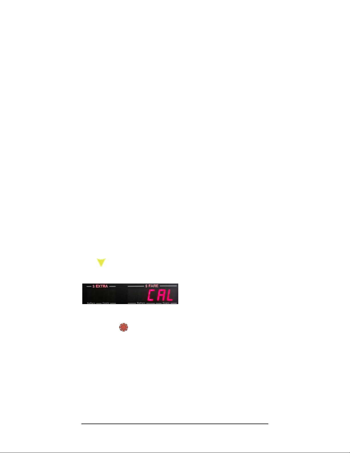
6.1 Set the Signal-Conditioner Value (VSS
Sensitivity)
CG3 models with serial number 31,000 and up have a built-in signal
conditioner that allow for adjusting the sensitivity of the VSS detector
circuit. This is helpful in either eliminating noise which can lead to
improper readings (i.e. the taximeter counts motion pulses when the
automobile is stationary), or can be used to detect weak signals (for
example, when a wheel sensor is the only available motion sensor
provided in the vehicle).
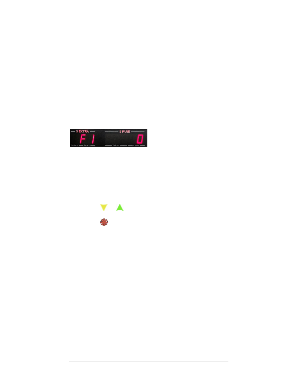
There are 73 levels (0-72) of sensitivity available.
0is the least sensitive setting.
72 is the most sensitive setting.
You should only adjust this value where necessary, based upon
trial and error:
1) If your taximeter counts pulses while the automobile is
stationary, you need to decrease the sensitivity (i.e. decrease
F2 value).
2) If your taximeter is not able to detect the VSS signal because it is
too weak, you need to increase the sensitivity (i.e. increase F2
value).
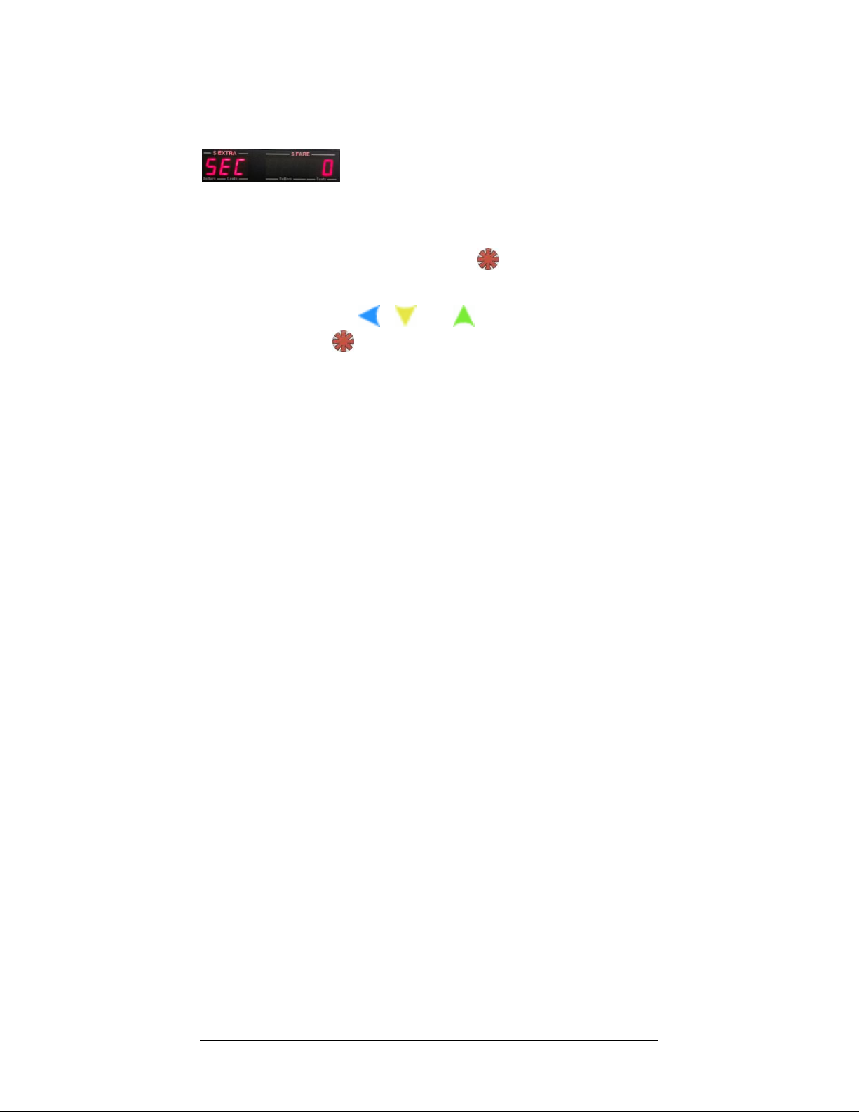
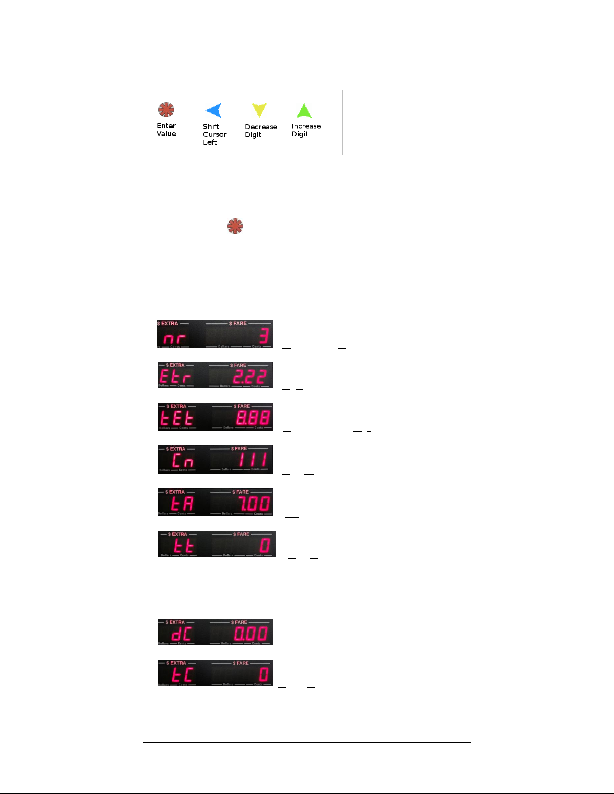
Press or to adjust the sensitivity value. Hold either
button in depressed state for rapid increment / decrement of
value.
Press to enter the value that you want into memory, and to
proceed to next step.
Later, you will have the option to fine-tune the sensitivity based on your
results during calibration of the CG3 (sections 4.4.9 and 4.4.9.1).

11
6.2 View / Manually Set Calibration Value
Next, the current calibration setting will be displayed (figure 16). You have the option
to: a) manually change the current calibration setting, or b) skip changing the calibration
value (in order to proceed to the calibration procedure).
Figure 7: Current calibration setting
a) To adjust the current calibration setting:
Press .
Use the , , and buttons to adjust the setting.
Press to enter the value into memory. This will then return the taximeter
to Vacant Mode
b) To skip adjusting the existing calibration, simply press . This will
automatically advance the taximeter into the Calibration Procedure (see the next
step).

12
6.3 Calibration Procedure
The purpose of this procedure is to determine the number of vehicle speed pulses
per km or mile. Before starting this step, drive the vehicle to a measured km or mile
start point. Bring the vehicle to a complete stop at the start point.
The next step puts the taximeter into a mode that counts pulses while the
automobile is in motion. At the start of the mode, the display will show a zero,
indicating that it is ready to start counting mileage pulses (see Figure 17). Begin
driving, and the taximeter will count pulses.
Figure 17: The Calibration Test initial value of 0 pulses counted.
Press to stop the test.
Press a subsequent time to restart the test.
Press to enter count into memory, and exit back to Vacant Mode.
NOTE: We recommend repeating the calibration procedure 2 –3 times to ensure that
the counts are fairly consistent. If you see a large variation between subsequent
calibration procedures, you may have a problem with your installation. In that case,
ensure that you are connected to the correct vehicle speed sensor wire, and that you have
grounded the taximeter to the car battery.
6.4 Adjusting the Sensitivity during Calibration
Procedure
figure 18: Signal Conditioner setting value displayed
If your CG3 has the built-in Signal-Conditioner i.e., the Serial Number is 31000
or greater (section 4.7), you can fine-tune adjust the sensitivity of the VSS
detector circuit repeatedly while in calibration mode. This is described next:
While in Calibration Test Mode:
Press to stop the test.
Press or to display the current sensitivity value.
Press or to adjust the value.
Press to enter new sensitivity value, and return to Calibration
Procedure.
You can repeat this procedure multiple times until you are satisfied with
the results.
Other manuals for CG3
1
Table of contents
Other Record Measuring Instrument manuals
Popular Measuring Instrument manuals by other brands

SEFRAM
SEFRAM 87 instruction manual

Hanna Instruments
Hanna Instruments HI98162 instruction manual

Traceable
Traceable Digi-Sense 98767-05 instructions

PCB Piezotronics
PCB Piezotronics 608A11/-0112 Installation and operating manual

Dräger
Dräger E-Cal station Instructions for use

Altek
Altek 2500T Specifications

Rover Instruments
Rover Instruments MASTERSAT Evo user guide

Demtech
Demtech Pro-Tester T-0100 Operator's manual

AEA
AEA VIA Bravo MRI operating manual

IPETRONIK
IPETRONIK M-THERMO 96 Hardware manual

New Cosmos Electric
New Cosmos Electric SDM-73 instruction manual

Bruker
Bruker DektakXT Installation and maintenance manual