Record BA 90 User manual

record PROTECT full turn
User manual
Translation of the original manual

Table of content
2 / 20 BAL_PROTECT_full_turn_EN_1V0_REC_102-905401101
Table of content
1 Safety................................................................................................................................................................. 3
1.1 Presentation of warning signs............................................................................................................... 3
1.2 Intended purpose of use ....................................................................................................................... 3
1.3 General hazards ................................................................................................................................... 3
1.4 State of technology ............................................................................................................................... 6
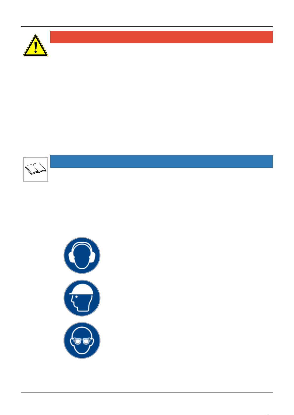
1.5 Personal protective equipment ............................................................................................................. 6
1.6 Spare parts and liability ........................................................................................................................ 7
2 General information ......................................................................................................................................... 8
2.1 Purpose and use of the instructions ..................................................................................................... 8
2.2 Document identification ........................................................................................................................ 8
2.3 Copyright .............................................................................................................................................. 8
2.4 Product identification ............................................................................................................................ 8
2.5 Manufacturer agtatec ag....................................................................................................................... 8
2.6 Target groups ....................................................................................................................................... 8
3 Description........................................................................................................................................................ 10
3.1 Product Description .............................................................................................................................. 10
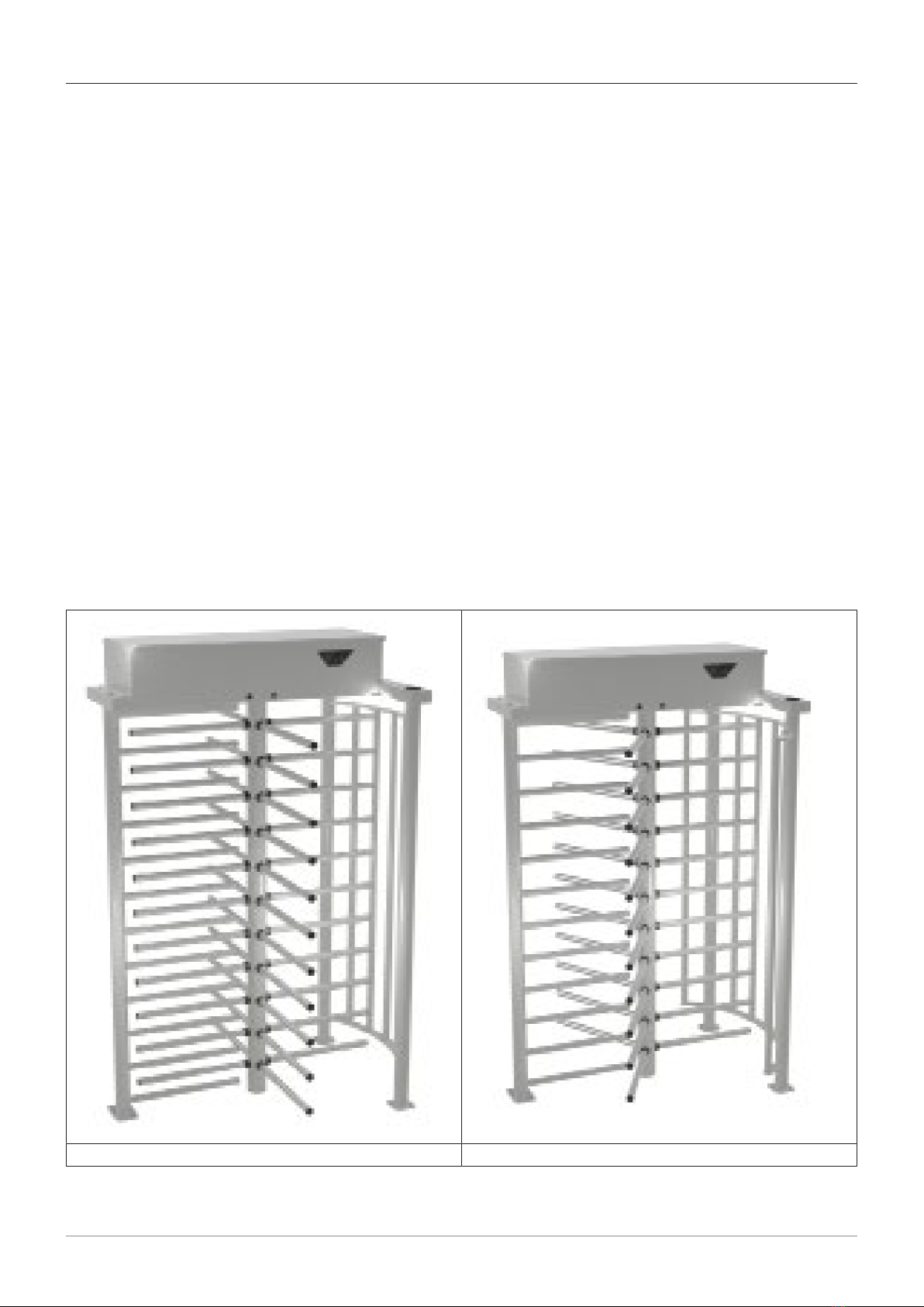
3.2 Model Build Variations .......................................................................................................................... 10
3.3 Technical Specification ......................................................................................................................... 12
3.4 Standard Technical Specification ......................................................................................................... 12
3.5 Alternative options and Accessories..................................................................................................... 13
4 Operation........................................................................................................................................................... 15
4.1 Instructions for Use............................................................................................................................... 15
4.2 Customer Instructions for use............................................................................................................... 16
4.3 Fail State............................................................................................................................................... 17
4.4 Access Control Devices........................................................................................................................ 17
4.5 Programmable Parameters................................................................................................................... 17
5 Servicing and maintenance ............................................................................................................................. 18
5.1 Maintenance ......................................................................................................................................... 18
6 Taking out of service and disposal................................................................................................................. 19
6.1 Decommissioning ................................................................................................................................. 19
6.2 Dismantling and disposal...................................................................................................................... 19

Safety 1
BAL_PROTECT_full_turn_EN_1V0_REC_102-905401101 3 / 20
1 Safety
1.1 Presentation of warning signs
Various symbols are used in this guide for easier understanding:
NOTICE
Useful advice and information to ensure correct and efficient workflow of the system.
IMPORTANT
Specific details which are essential for trouble-free operation of the system.
IMPORTANT
Important details which must be read for proper function of the system.
CAUTION
Against a potential hazardous situation that can lead to minor personal injury and property
damage.
WARNING
Against a latent hazardous situation that can lead to severe injuries or death and cause sub-
stantial property damage.
DANGER
Against an imminent hazardous situation that can lead to severe injury or death.
DANGER
Against an imminent or latent hazardous situation that could lead to electric shock and cause
serious injury or death.
1.2 Intended purpose of use
The system is designed exclusively for use as a pedestrian passage. The installation may only occur
in dry areas. If there are deviations then proper waterproofing and water drains will be required on-
site.
Any other application or use beyond this purpose is not considered to be an intended purpose. The
manufacturer bears no liability for any resulting damage; the operator alone shall bear the associated
risk.
The intended purpose also includes observation of the operating conditions specified by the manufac-
turer, in addition to regular care, maintenance and repair.
Interventions in or alterations to the installation performed by non-authorized maintenance technicians
exclude the manufacturer's liability for consequential damages.
1.3 General hazards
The following section lists hazards that can be caused by the system even when used as intended.
To reduce the risk of malfunction, damage to property or injury to persons and to avoid dangerous
situations, the safety instructions listed here must be observed.

1Safety
4 / 20 BAL_PROTECT_full_turn_EN_1V0_REC_102-905401101
The specific safety instructions in the other sections of this manual must also be observed.
IMPORTANT
The country-specific regulations must be observed and complied with!
IMPORTANT
To avoid malfunctions, moving objects such as flags or parts of plants must not be allowed to
enter the detection range of the sensors.
CAUTION
Risk of malfunctions, material damage or injury due to improper settings!
a) Improper settings can lead to malfunctions, material damage or personal injury.
ðDo not disconnect the system from the power supply overnight.
ðSettings should only be made by personnel qualified to do so.
ðDo not disassemble, put out of operation or manipulate safety devices.
ðHave faults rectified by specialist personnel or by personnel qualified to do so.
ðHave service and maintenance carried out according to locally applicable regulations or accord-
ing to a maintenance contract.
CAUTION
Risk of malfunctions, material damage or injuries due to insufficient or missing cleaning or
care!
a) Insufficient or inattentive cleaning or care of the system can lead to malfunctions, damage to
property or injury to persons.
ðCheck the sensors regularly for dirt and clean them if necessary.
ðRegularly remove dirt accumulations in the floor rail or under the floor mat.
ðKeep the system free of snow and ice.
ðDo not use aggressive or caustic cleaning agents.
ðUse road salt or loose chippings only conditionally.
ðLay the floor mat without folds and flush with the floor.
ðEquipment required for cleaning purposes such as ladders or similar must not be leaned on or at-
tached to the system.
CAUTION
Risk of material damage or injury due to unforeseen opening, closing or turning of the door!
a) The door can open, close or turn unexpectedly. This may result in damage to property or injury
to persons.
ðNo persons may be present in the opening area of the system.
ðEnsure that moving objects such as flags or parts of plants do not enter the detection range of
the sensors.
ðDo not make any settings on the control unit when the system is in use.
ðHave faults rectified immediately by specialist or personnel qualified to do so.
ðRemove objects from the opening area.
ðDo not disassemble, put out of operation or manipulate safety devices.
ðDo not rush through a closing system.

Safety 1
BAL_PROTECT_full_turn_EN_1V0_REC_102-905401101 5 / 20
CAUTION
Risk of bruising and severing of limbs!
a) If the system moves, careless behaviour can lead to serious injuries to limbs or severance of
limbs.
ðDo not reach in when parts of the system are moving.
ðKeep a distance when parts of the system move.
ðDo not bump into or touch the system when it is moving.
ðDo not open or remove protective covers during operation.
ðDo not permanently remove covers from the system.
ðOnly carry out inspection, service, maintenance and cleaning when the system is stationary and
switched off.
CAUTION
Danger of material damage or injury due to non-functioning safety devices!
a) If safety devices are not functioning, manipulated or put out of operation, there is a risk of dam-
age to property or injuries that can lead to death.
ðNever disable or manipulate safety devices.
ðHave inspection, service and maintenance of the safety devices carried out according to local
regulations or according to a maintenance contract.
CAUTION
Danger of malfunctions, damage to property or risk of injury if used by unauthorised persons!
a) If unauthorised persons use the system, there is a risk of malfunction, damage to property or in-
jury to persons.
ðChildren under 8 years of age may only use the system under supervision.
ðChildren must not play with or on the system or clean and maintain it.
ðPersons with limited physical, sensory or mental abilities as well as persons with insufficient
knowledge or experience may only use the system under supervision or must have received and
understood instructions to do so.
DANGER
Danger to life due to electric current!
a) In case of contact with live parts, there is an immediate danger to life due to electric shock.
Damage to or removal of the insulation or individual components can be life-threatening.
ðBefore starting work on active parts of electrical systems and equipment, ensure that all poles are
voltage free and that this is maintained for the duration of the work.
ðKeep moisture away from live parts. This can lead to a short circuit.
ðNever bridge fuses or put them out of operation.
ðDo not connect the power supply until all work has been completed.
ðHave work on the electrical system performed by qualified personnel only.

1Safety
6 / 20 BAL_PROTECT_full_turn_EN_1V0_REC_102-905401101
DANGER
Danger to life due to non-functioning safety devices of the fire protection system!
a) If safety devices of the fire protection system do not function properly, there is a risk of serious
or fatal injuries.
ðNever disconnect the fire protection system from the power supply overnight.
ðDo not disassemble, put out of operation or manipulate safety devices.
ðDo not remove safety instructions on the system.
ðNever block, hold open or otherwise prevent fire doors from closing.
ðHave inspection, service and maintenance of the fire protection system carried out in accordance
with locally applicable regulations or according to a maintenance contract.
ðHave the fire protection system checked and maintained according to the state of the art.
1.4 State of technology
This system was developed using state of the art technology and officially recognized technical safety
regulations. The system, depending on its options and diameter, comply with the requirements of the
Machine Guidelines 2006/42/EG as well as EN 16005 and DIN 18650 (D).
Nevertheless, danger may arise if not used as intended.
IMPORTANT
Installation, commissioning, inspection, maintenance and repair work may only be conducted
by qualified, trained and authorized technicians.
After commissioning or repair work, fill in the check list and give it to the customer for safe
keeping.
We recommend obtaining a service agreement.
1.5 Personal protective equipment
Personal protective equipment is used to protect persons from adverse effects on safety and health.
Personnel must wear personal protective equipment during the various work activities on and with the
system.
Personal protective equipment is explained below:
Hearing protection is used to protect the hearing from noise. As a rule of
thumb, hearing protection is compulsory from when normal conversa-
tion with other people is no longer possible.
The head protection serves to protect against falling and flying parts
and materials. It also protects the head from bumping into hard objects.
Protective goggles protect the eyes from flying parts, dust, splinters or
splashes.

Safety 1
BAL_PROTECT_full_turn_EN_1V0_REC_102-905401101 7 / 20
Protective gloves are designed to protect hands from friction, abrasions,
punctures or serious injury and from burning caused by contacting hot
surfaces.
Safety shoes protect the feet from crushing, falling parts and slipping on
surfaces. The puncture resistance of the shoes ensures, that pointy ob-
jects do not penetrate the foot.
The high-visibility vest is used to make the personnel stand out and
therefore to be seen. With improved visibility and attention, the high-vis-
ibility vest protects personnel in busy work areas from collisions with
vehicles.
Depending on the place of work and the working environment, the protective equipment varies and
must be adapted accordingly. In addition to protective equipment for specific work, the work site may
require other protective equipment ( for example a harness).
In hygiene-protected areas, special or additional requirements of personal protective equipment may
be required. These requirements must be considered when choosing personal protective equipment.
If there is any uncertainty regarding the choice of personal protective equipment, the safety officer
must be consulted at the place of work.
1.6 Spare parts and liability
Reliable and trouble free operation of the door is only guaranteed when using parts that were recom-
mended by the manufacturer. The manufacturer declines any liability for damages resulting from un-
authorized modifications to the door or the use of parts that are not permitted.

2General information
8 / 20 BAL_PROTECT_full_turn_EN_1V0_REC_102-905401101
2 General information
2.1 Purpose and use of the instructions
These instructions are an integral part of the system and enable efficient and safe handling of the sys-
tem. In order to ensure proper functioning, the instructions must be accessible at all times and kept in
the immediate area of the system.
Although only the male form has been chosen for reasons of better legibility, the information refers to
members of both sexes.
The operator must have read and understood the manual before starting any work. The basic require-
ment for safe working is to follow the safety instructions and the handling instructions. In addition, the
local regulations and safety rules apply.
The manual can be handed over in extracts to instructed personnel who are familiar with the opera-
tion of the system.
The illustrations are for basic understanding and may differ from the actual presentation. Specific rep-
resentations are contained in the drawings.
2.2 Document identification
Name: BAL_PROTECT_full_turn_EN_1V0_REC_102-905401101
Version: V1.0
Article nr: 102-905401101
Publication date: 03/2021
2.3 Copyright
The copyright of the instructions remain at:
agtatec ag
It is prohibited to reproduce, distribute or use the manuals for purpose of competition without the writ-
ten authorization of agtatec ag.
Violation of the here stated copyrights will be prosecuted and fined with compensation of damage.
Differences between product and manual are thereby possible.
2.4 Product identification
The nameplate located on the door provides accurate identification of the product.
2.5 Manufacturer agtatec ag
agtatec ag
Allmendstrasse 24
CH – 8320 Fehraltorf
Switzerland
Phone: +41 44 954 91 91
Fax: +41 44 954 92 00
2.6 Target groups
CAUTION
Risk of injury if personnel are insufficiently qualified!
If unqualified personnel work on the system or are in the danger zone of the system, dangers may
arise which can cause serious injuries and considerable damage to property.
a) All work must be carried out by qualified personnel only.
b) Keep unqualified personnel away from danger areas.
This operating manual is intended for the target groups listed below:

General information 2
BAL_PROTECT_full_turn_EN_1V0_REC_102-905401101 9 / 20
– Operating entity of the system:
the person who is responsible for the technical maintenance of this system
– Operator of the system:
the person who operates the system every day and has been suitably instructed

3Description
10 / 20 BAL_PROTECT_full_turn_EN_1V0_REC_102-905401101
3 Description
3.1 Product Description
The record full turn BA/EV features a modern modular design concept that makes it perfect for all ex-
ternal applications such as defence and industrial sites.
An all welded steel rotor with straight arms runs in a phosphor bronze bearing at the top and is sup-
ported by a maintenance free polymer bearing at the base.
The full turn can be provided in a choice of RAL colours, 304 grade and 316 grade stainless steel.
On double units the rotors are interlocked for increased security.
Entry and Exit can be made by card reader, or any other type of control device specified by the client
at the time of order.
The full turn is controlled by the Titan mechanical head and LL2001 logic platform, which are secured
in a weather proof containment box.
3.2 Model Build Variations
The following variations can be supplied by ; however this technical manual provides sufficient inform-
ation to cover all models.
BA Units
Full turn BA: Simple painted steel tubular structure(with stainless steel rotor column) or stainless steel
structure. The full height ot the full turn is delivered in kit form allowing reduced transport costs or in
monoblock form allowing reduced installation time and cost.
The full turn is available with a 90º and 120º rotor.
It is also available as a Single rotor for one lane or a Double Interlocking layout for two lanes see (EV
DI model).
BA 90 Single- Basic model. BA 120 Single- Basic model

Description 3
BAL_PROTECT_full_turn_EN_1V0_REC_102-905401101 11 / 20
EV Units
With enhanced side protection,painted steel tubular structure(with stainless steel rotor column) or
stainless steel structure.
The full height is delivered in kit form allowing reduced transport costs or in mono-block form allowing
reduced installation time and cost.
The full turn is available with a 90º and 120º rotor.
It is also available as Single rotor for one lane. The EV Double Interlocking layout for two lanes, also
fully matches with the BA aesthetics.
EV 90 Single- Evolution Model EV 120 Single- Evolution Model

3Description
12 / 20 BAL_PROTECT_full_turn_EN_1V0_REC_102-905401101
EV 90 Interlocking Double- Evolution Model EV 120 Interlocking Double-Evolution Model
3.3 Technical Specification
An all welded steel rotor with straight arms runs in a phosphor bronze bearing at the top and is sup-
ported by a maintenance free polymer bearing at the base.
Entry and exit can be made by card reader, push button or any other type of control device specified
by the client at the time of order. All controls are housed within the unit, therefore NO separate
switches or control boxes are required. Control of the rotor is achieved by an electromechanical head
mounted within the top section and accessible by removing the access panel, featuring,
– A positive action lock which prevents two passages at one time.
– A self-centring mechanism to ensure complete rotation of the head to the reset/home position.
– An anti-backup device prevents reverse rotation when the head has moved more than 32° from
the reset/home position.
3.4 Standard Technical Specification
Orientation: Pass left or pass right
(Pass left available with locks on secure side)
Rotor Wings: 4NO for the full turn 90
3NO for the full turn 120
Drive: Manually operated
Materials / Casework: Box and round hollow section electrophoresis treated
under a final smooth gloss polyester powder
top coat, for painted version, or stainless steel
AISI 304 grade ( upgradable to 316 grade as option), for the stainless steel
version.
Rotor Column: The central rotating column of the rotor assembly is
stainless steel grade 304 ( upgradable to 316 as option), same as for the
horizontal bars, further with black plastic end caps and joint rings.

Description 3
BAL_PROTECT_full_turn_EN_1V0_REC_102-905401101 13 / 20
Canopy (Option): Aluminium frame with 4mm thick polycarbonate
transparent infill or grey solid infill, with connecting
brackets to the unit frame in stainless steel AISI 304 grade ( upgradable to
316 grade as option)
Function: Passage in both directions, electronically controlled.
Mechanism: Control operation is achieved by an
electromechanical head mechanism. Head damping available as an op-
tional extra.
Security: Passage through the “dead area” is prevented by stator bars.
Power Supply: 115/230 Vac 50/60Hz
Power Rating: Standby or Passage 50Va (Alarm Condition 50Va)
* Heater Kit Option add 400W
Logic Voltage: 24Vdc
Power Failure: In the event of an emergency or isolation of the power supply the full turn
can be configured to Fail- Safe i.e. Rotates freely or Fail-Lock i.e. locks in
the HOME position. Either option is available in one or both directions. (As
standard the full turn is configured bi-directional fail-safe unless requested
during the ordering process) This is configurable on site if required.
Fire Alarm: Input facility available for 0V contact supplied by others to effect fail state.
Interface: The mechanism is controlled by means of the LL2001 microprocessor con-
trol logic with the following features:
The basic features of the board are as follows:
– One input for unlocking the Titan-Lite FHT for transit in direction ‘A’;
– One input for unlocking the Titan-Lite FHT for transit in direction ‘B’;
– Two pairs of protected outputs for driving the traffic lights (Red and Green) in directions ‘A’ and
‘B’;
NOTICE
Two pairs of protected outputs can be used for driving the Red and Green lights in direction A
(PL) and B (PR). In this mode the remaining two outputs can be used for indicating availability
of use or for counting passage in either direction.
Two outputs that can be directed to relays with voltage free contacts to provide an interface
with external components;
– One relay output with voltage free contact for alarm signalling;
– Six TTL inputs for optional devices connection;
– Fast acting fuses 5 x 20mm, 2A / 250V;
– RS485 asynchronous serial line; (Protocol available on request)
– Two NPN outputs that can be used to provide an interface with external components.
– Programmable by means of Trimmers;
– Microprocessor reset button;
– One output that can be directed to a relay with voltage free contacts to provide a TECHNICAL
Alarm
– TABELLE
Operating Temperature: 5°C to +50°C 10°C to +50°C (With optional heater Kit)
– Transportation and Storage: -25°C to +55°C
– Note - This Technical Manual is applicable to all variants.
3.5 Alternative options and Accessories
– Alternative finishes and materials.
– ITC (Improper transit control) Detects users entering the unit in the wrong direction ( with Audible
alarm ) Confirms an authorized passage has been completed

3Description
14 / 20 BAL_PROTECT_full_turn_EN_1V0_REC_102-905401101
– Card reader integration.
– Canopy
– Baseplate
– Fully assembled option
– Traffic lights (LED)*
– Down lights (LED)
– All units come with the blanking panel for traffic lights, but if required the LEDs must be ordered
separately as they are an optional extra.
– Heel protection (optional) in black in Foamed nitrile rubber with polymeric covering for increased
safety in use is available

Operation 4
BAL_PROTECT_full_turn_EN_1V0_REC_102-905401101 15 / 20
4 Operation
4.1 Instructions for Use
The information contained in this section should be used as a basis for the instruction of personnel in
the correct use of the doors.
BA 90° Single BA 120° Single
EV 90° Single EV 120° Single

4Operation
16 / 20 BAL_PROTECT_full_turn_EN_1V0_REC_102-905401101
EV 90° Double Interlocking EV 120° Double Interlocking
4.2 Customer Instructions for use
The operating procedure is shown below and given the sequence of passage through the full turn in
either direction.
1. The Rotor will normally be locked, unless a free entry/exit option has been specified.
2. Operate the Access Control Device if fitted.
3. On the acceptance of a signal from the Access Control Device the rotor will unlock and be free to
rotate in one direction
4. Pass through the full turn, using your arms to manually push the rotor.
5. The rotor will automatically lock in its new position once the passage has been completed
Important Notices –
– Only one person at a time should pass through the full turn.
– Large packages should be carried in front of you.

Operation 4
BAL_PROTECT_full_turn_EN_1V0_REC_102-905401101 17 / 20
– Should any article become caught in the rotor, STOP, and DO NOT keep forcing through in the
same direction.
4.3 Fail State
The full turn can be set to fail lock (FSL) or fail safe (FSO) in either direction via alteration of the
solenoids and programmable parameters.
The fail state is the same as when a fire alarm signal is received.
4.4 Access Control Devices
can supply the mounting for an Access Control Device, which is specified at the initial order to meet
customer requirements.
4.5 Programmable Parameters
The system operation is conditioned by the values of the 8 trimmers stored in the LL2001 PCB Con-
trol Logic. The system operation is conditioned by the values of the 8 trimmers stored in the LL2001
PCB Control Logic.

5Servicing and maintenance
18 / 20 BAL_PROTECT_full_turn_EN_1V0_REC_102-905401101
5 Servicing and maintenance
5.1 Maintenance
The Hercules mechanism should be inspected and cleaned at regular intervals in order to maintain
the components in good working order and to check for signs of wear.
The following information refers to a typical installation where the average number of transits per year
is equal to ONE Million To avoid the risk of electric shock, always ensure that the electrical power is
disconnected before inspecting the mechanism.
The Hecules-Lite Tripod should be cleaned and greased at regular intervals, using the following ap-
proved materials.
Routine cleaning, all finishes
Cleaning agent: Soap or mild detergent water.
Action: Sponge rinse with clean water, wipe dry as necessary
Stubborn stains and discolouration, all finishes
Cleaning agent: Mild cleaning solutions or domestic service cleaners.
Action: RInse well with clean water and wipe dry.
Oil, Grease marks, all finishes
Cleaning agent: Organic solvents (acetone, alcohol, genclene, trichlorethane).
Action: Clean after with soap and water, rinse well with clean water and wipe
dry..
Rust and other Corrosion products, Stainless finishes
Cleaning agent: Oxalic acid. The cleaning solution should be applied with a swab and al-
lowed to stand for 15 to 20 minutes before being washed away with wa-
ter. Continue using a domestic surface cleaner to give a final clean.
Action: Rinse well with clean water (precautions for acid cleaners should be ob-
served).
Minor scratches on painted surfaces
Cleaning agent: Lightly rub with cutting paste. Rinse area with water and dry. Apply touch-
up paint in fine layers.
Action: Allow 2 weeks to harden. Blend into surrounding paint work, using fine
cutting paste.
Deep scratches on painted finishes causing rust
Cleaning agent: Remove rust with a small sharp knife. Apply rust inhibiting paint. Fill
scratch with fine body filtert o just under finished surface. Follow proced-
ure for minor scratches.
Greasing
Cleaning agent: None
Action: Carried out by the service technician as part of service maintenance.

Taking out of service and disposal 6
BAL_PROTECT_full_turn_EN_1V0_REC_102-905401101 19 / 20
6 Taking out of service and disposal
6.1 Decommissioning
When shutting down or taking out of service, the system is disconnected from the mains supply and
any existing battery is unplugged.
NOTICE
After each temporary shutdown a new commissioning must be carried out.
6.2 Dismantling and disposal
IMPORTANT
All machine parts must be sorted by type of material and disposed of according to
local regulations and guidelines.
NOTICE
The door systems can be completely disassembled in reverse order.
The automatic door mainly consists of the following materials:
Aluminum:
– Linking profiles
– Gearbox, Drive panel
– Door wing profiles and side profiles
– Various profiles and small parts
Steel / iron parts:
– Stainless steel casing, Floor panel, Box recess for floor installation
– Optional spacer or reinforcement profiles
– Gear components, springs
– Various small parts like fittings, covers, linking parts, etc.
Glass:
– Door wings and side panels
Various electronic and electromechanical components:
– Sensors, control and operator components
– Lead batteries and nickel-cadmium rechargeable batteries
Various plastics:
– Rollers
– Cable clips, coupling and linking parts
– Sealing profiles
– Casing of electromechanical components and sensors

record Group
www.record.group
Great Britain
www.recorduk.co.uk
Australia
www.recorddoors.com.au
Canada
www.recorddoors.com
China
www.record.net.cn
Deutschland
www.record.de
Denmark
www.record-danmark.dk
España
www.record.es
France
www.record.fr
Malaysia
www.recorddoors.my
Polska
pl.record.global
Schweiz
www.record.ch
Sverige
www.record.se
Türkiye
tr.record.global
United States
www.recorddoors.com
record global export
www.record.global
Subject to technical modifications
Copyright © agtatec ag
No. 102-905401101
This manual suits for next models
1
Table of contents
Other Record Turnstile manuals
Popular Turnstile manuals by other brands

BOON EDAM
BOON EDAM Speedlane 900 Operation installation and maintenance

BOON EDAM
BOON EDAM Trilock 50 Instruction card

BOON EDAM
BOON EDAM Circleslide Instruction card

ZKT
ZKT T Series user manual

LBA GROUP
LBA GROUP LBAT10 operating instructions

Magnetic Autocontrol
Magnetic Autocontrol MPT-152 operating instructions