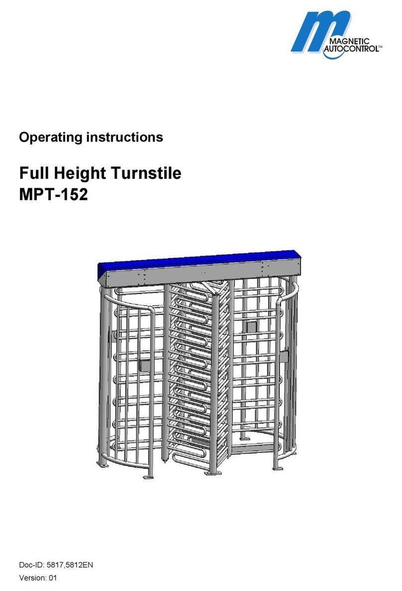
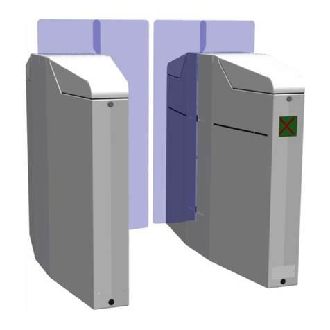
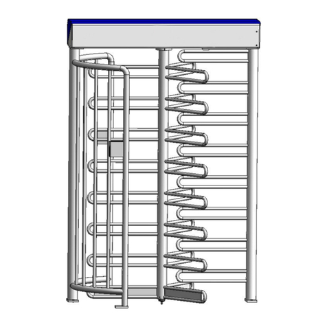
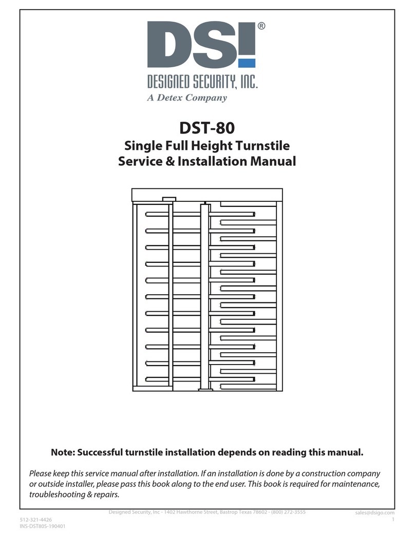
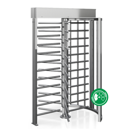
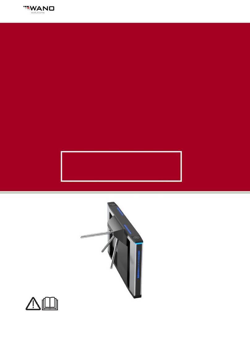
Magnetic Autocontrol MPT 33 User manual

Operating Instructions
581E,5811_07 1
Operating Instructions
Pedestrian Turnstile
Type MPT 33

Operating Instructions
581E,5811_07 2
Contents
1. Delivery ....................................................... 3
2. Safety.......................................................... 3
3. Description and operation ........................... 6
4. Foundation ............................................. 8-10
5. Assembly and installation..................... 11-17
6. Electrical connection ............................ 18-19
7. Access control devices.............................. 20
8. Commissioning........................................ ..21
9. Controller MSC 10..................................... 22
10. Adjustable parameters. ............................. 24
11. Operation modes....................................... 26
12. Technical support...................................... 28
13. Spare parts and accessories................ 28-30
14. Instructions for exchange and
adjustment of micro switch. 31
15. Warranty......................................................31
16. Decommissioning and disposal..................32

Operating Instructions
581E,5811_07 3
1.Delivery
The Security Turnstile consists of:
1 x Semi cage made of stainless steel or mild steel
1 x Center column 3 x 120°, stainless steel or mild steel
1 x Top housing with locking unit
1 x U-bar locking unit
1 x Electronic controller MSC10
1 x Set of documents inside the lockable top cover
1 x Fixing anchors (in Europe only)
2 x Keys for the top cover
2.Safety
2.1 General safety notes
The Magnetic pedestrian turnstile has been designed, built and tested
according to the latest technology. Although it has left the factory in a fully
operational and safe condition, it is important that the installation is carried out
correctly therefore the operating instructions must be read carefully and the
safety notes must be observed.
Any liability and warranty is declined by the manufacturer in the case of
incorrect use and use for purposes other than intended.
2.2 Use for the intended purpose
The Magnetic pedestrian turnstile may be used only to control pedestrians
entering or exiting restricted areas, usually under surveillance.
The Magnetic Universal Controller may be used only for controlling the
Magnetic pedestrian turnstile. Any other use is not permitted.
Conversions and modifications to the turnstile or to the control modules are
not permitted.
Only original spare parts and accessories from Magnetic may be used.
Technical Data: Type
Protection IP
Voltage VAC
Frequency Hz
Current A
Duty Cycle %
Weight Kg
Height mm
Diameter mm
MPT 33
43
230
50
2,5
100
320
2230
1300

Operating Instructions
581E,5811_07 4
NOTE!
MAGNETIC does not assume responsibility for any damages or injuries to
persons that result from non-observance of the operating instructions or
inappropriate use!
2.3 Warnings and symbols used in this manual
The following symbols and references are used in this manual to give instructions
and warnings (cautions) of particular importance. These must always be strictly
observed!
Purchased components may have additional specific warnings that also need to
be strictly observed.
WARNING!
This Symbol indicates an imminently hazardous situation which, if not
avoided, will result in death or serious injury.
The description of the situation is followed by measures of avoidance.
Please read and observe the given instructions very carefully.
CAUTION!
This Symbol indicates a potentially hazardous situation which, if not avoided,
could result in property damages and material destruction.
The description of the situation is followed by measures of avoidance.
Please read and observe the given instructions very carefully.
NOTE!
The symbol “note” is used in case of an operating procedure or condition
which is essential and, therefore, noted to gain special attention.
In addition the symbol indicates a potentially situation which, if not avoided,
may result in an undesirable result or state.

Operating Instructions
581E,5811_07 5
RECYCLING!
When disposing of the unit at the end of utilisation ensure those noxious and
dangerous residues are disposed of in accordance with the regulations.
Based on the different material, disposal must occur in a separate manner.
The used lubrication and auxiliary material such as oils and fats will be
disposed of in accordance with the statutory provisions.
2.4 Safety notes
- Disconnect all external opening or closing devices (remote control, control
desk, etc.) during maintenance work.
- Do not operate the equipment without effective anchoring to the
foundation.
- A main supply power circuit breaker must be installed.
- This operating manual and any other additional information must be kept
in a, for all authorized person, accessible location.
- Before commissioning make sure all electrical and functional features are
tested.
- The electrical wiring must comply with these instructions.
- Only certified and trained electrical technicians shall perform any
electrical work.
- Before any maintenance or troubleshooting work the main power supply
must be disconnected.
- Electrical voltage components like transformers, solenoids, resistors, and
stator housings of motors, lamps etc. may be hot during and after
operation. Do not touch such components; it can cause skin burns.
●Disconnect all external opening or closing devices (remote control, control
desk, etc.) during maintenance work
●It is prohibited to install the barrier without proper mounting to the
foundation
●A main power switch or residual current operated device is compulsory
●Risk of bodily harm while cover is open
●Pedestrian barriers are maintenance free
●Documentation should be easily accessible.
●Before commissioning make sure all electrical and functional features are
tested.
●Permissible environmental conditions
Operating Instructions
581E,5811_07 6
●The electrical wiring of the barrier must comply with the included drawings.
●Only certified and trained electrical technicians may perform the electrical
connections
●Only certified and trained electrical technicians may remove covers for
mains plug, mains receivers or wirings
●Before repairing electrical failures disconnect fuse
●Risk of bodily harms while closing the cover
●As part of the maintenance work, the fixing bolts must be checked and
tightened, if necessary.
●Current carrying components like transformers, solenoids, resistors, stator
housings of motors, lamps etc. shall not be touched while in operating-
temperature condition; this can cause skin burns
3. Product description
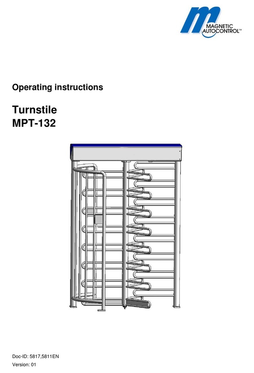
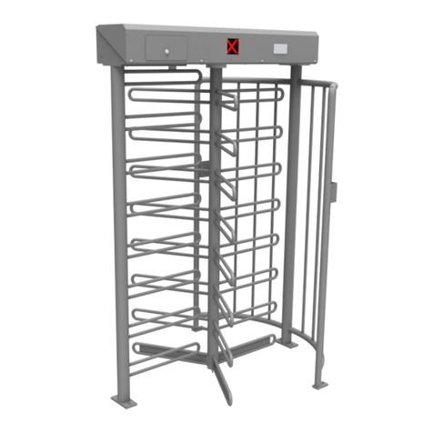
The MPT series of turnstiles are designed to control pedestrians entering or
exiting restricted areas outside in high security situations. The turnstile
consists of four different component parts (see fig. 1) It can be used for bi-
directional access control by means of keys or card readers (access control
devices in general). Entry and exit of the barrier can either be operated in
open, controlled or closed modus. The rotating centre column consists of 3 x
120 degree U bars. The controller, the drive units and the locking device are
mounted on top of the centre unit in a powder coated sheet metal enclosure,
where there is also space for additional access control equipment .Locking
and release of the centre is realized by an electro-mechanical locking device
with solenoids.

Operating Instructions
581E,5811_07 7
1
components
3
2
4
Fig. 1 Design of components
1 Lock comb
2 Cage half(s)
3 Upper housing with locking unit
4 Center column

Operating Instructions
581E,5811_07 8
Fig. 2.1 Entry “left version” Fig. 2.2 Entry “right version”
Fig.2
Entry “left version”

Operating Instructions
581E,5811_07 9
4. Foundation
A level concrete mounting surface is required to secure the turnstile housing.
For the dimensions please refer to figure 2. The cables should finish a
minimum of 5 meters above the finished concrete surface.
NOTE: This foundation is also required in connection with a foundation frame.
Conduits for mains supply and data lines
should finish 50 mm approx. above foundation
Fig.3
Passage direction
Passage direction
bearing
Empty conduit
Empty conduit
Foundation anchor pin
with inside thread M10
Drilling hole Ǿ16
Drilling depth 90 mm

Operating Instructions
581E,5811_07 10
Concrete PC 250
with iron reinforcement
srew
split washer
washer
washer
socket
bearing neck
bearing
empty conduit
O 25 mm
Foundation, smoothed finish
to be positioned in water
in a level and horizontal manner
Lay seperate conduits for
power supply and data cables,
50 mm approx. above foundation
All power supply and
data lines are to be 5 m at least
above the empty conduit
After mounting
glue set screw with LOCTITE 241
or similar
Fig.4

Operating Instructions
581E,5811_07 11
4.1 Foundation frame
The foundation frame is required for turnstiles to be mounted on an uneven
surface, for example in case of pavers. A level concrete mounting surface is
required for correct mounting of the foundation frame. It should be approx.
150 mm below the finished surface.
The foundation frame must be positioned in its desired location taking care on
which side (right or left), you want to place part 2. This is important in case
you want to mount access control units at part 2.
(See Fig 2.1 / 2.2, Fig. 5.1 / 5.2, Fig. 6)
Installation of the foundation frame:
First of all put the frame in place
Drill the fixing holes
Insert the fixing screws
Install the foundation frame by means of jackscrews in water
(if needed, even out with suitable underlayment)
Then fix the foundation frame
Pay attention to correct cable guiding to the turnstile
Empty conduits must not be squeezed
Please consider the cure time of the chemical anchor studs
With the installed foundation frame, the mounting of the turnstile can be
carried out in the same way as on a concrete foundation. (See chap. 5)
5 Fundamentdübel(F)
Express-Anker M12x153/55 A4
Bohrloch Ǿ12
Bohrtiefe 145 mm incl. U-Profilhöhe
Cable routing from foundation
into turnstile
Jackscrews
For positioning the foundation
frame on the concrete, if necessary.
Fig.5
Fig. 5.1 Entry Left version
Fig. 5.2 Entry Right version

Operating Instructions
581E,5811_07 12
5. Assembly and installation
5.1 To fit the turnstile (above ground foundation)
The turnstile should be positioned in its desired location taking care on
which side (right or left) you want to place part 2. (See Fig. 2.1/ 2.2, Fig. 6 )
This is important in case you want to mount access control units at part 2.
Set Foundation drillings 7 x M16 as per drilling plan figure 3!
Use the provided drilling template
Mount threaded rod (see enclosed separate description)
Wait till bolts are cured (see separate description)
Mount the components in correct order (part 1, 2..) onto the foundation,
however, do not tighten entirely the bolts in order to compensate any drilling
offset which may occur afterwards. Use screws 6 x M 10 x35. Grease the
screws before.
Place part 3 upon part 1 and 2. Use screws 8 x M12 x 35 and counternut.
This part of installation is dangerous. Make sure, that nobody stays
under Part 3, until this part is securily fixed.
Mount lower bearing (see fig. 8). Using screws M10 x 70. Grease them
before.
Put part 4 on the lower bearing, see fig. 10 and 11 and screw it up by means
of 4 x M16 x 40 with U-discs and flange. Be sure that the turnstile is in locked
position. (Please consider the marking of the flanges!) see fig. 12
Now tighten all fixing bolts.
p
art 3
p
art 1
part 2
part 4
Fi
g
.
6
Note:
Part 3 should be mounted, that
the cover is to open from the
secure side (inside).

Operating Instructions
581E,5811_07 13
5.2 Fixing on foundation frame
See section 5.1 fixing the foundation.
However in this case the turnstile is mounted on the flanges of the foundation
frame.
Fixing of foundation frame, see section 4.1
5.3 Opening of the top cover
1
Fig.7
The hood is fixed with 4
hexagon socket screws.
Unscrew them with an allen
key. (fig. 7).
Lift-off the hood (towards
yourself) (fig. 7.1)
Fig.7.1

Operating Instructions
581E,5811_07 14
To fit the turnstile (above ground foundation)
Fixing of the turnstile is done by means of the 8 fixing bolts M8 and plain
washer.
After final positioning tighten all bolts firmly.
Please consider the home position of the locking unit when mounting the center
column.
Note:
1.Mark the dimensions
onto foundation acc. to fig.4
2. Drill
3. Install turnstile
4. screw together (see fig. 5.1
Fig. 8
Fig. 9 Upper housing with locking unit

Operating Instructions
581E,5811_07 15
Fig. 9.1 Locking unit
Fig. 9.2 ▼The home position is reached, when the Countersink is in the
p
osition as shown
(
fi
t
-
u
p
aid
)
Fig. 9.3 ▼Home Position bottom view
▼
▼

Operating Instructions
581E,5811_07 16
5.5 To fit the centre column
Mount the lower bearing on the foundation and stick the centre column on it.
Fig. 10
Fig. 11

Operating Instructions
581E,5811_07 17
Fix the centre column by means of the delivered screws M16 at the top
flange.
Make sure the centre is in correct position (centre in locked position).
(Locking crest in locked position – see drawing)
Fig. 12
Center column
“blocked” position !!!
Cage halves
Cage halves
Lock comb
Lock comb
Center column
“blocked” position!!!
Fig. 13 Setting the turnstile to the „blocked“ position
Marking on the flange of the center column is face to face with lock comb!

Operating Instructions
581E,5811_07 18
AEINZELHEIT A
1. Fix the center column to the floor bearing using 3 headlees screws.
2. Tighten all 3 headless screws equally,so that the center column canbe
rotated smoothly in both directions.
3. Secure headless screws using Loctite 241 or similar.
Fig. 13.1

Operating Instructions
581E,5811_07 19
5.6 Assembly of roof with drain
Assemble the roof as shown on Fig.14.The roof can also be mounted rotated by
180°.
Fig.14

Operating Instructions
581E,5811_07 20
6. Electrical connections
Connection of mains supply should only be performed b y a certified electrian
and According to the connecting diagram or after discussion with the supplier.
Fig. 16
Connection unit with control unit MSC10
Fi
g
.1
5
Fig.16
Table of contents
Other Magnetic Autocontrol Turnstile manuals

Magnetic Autocontrol
Magnetic Autocontrol MPT-132 User manual

Magnetic Autocontrol
Magnetic Autocontrol MPT-333 User manual

Magnetic Autocontrol
Magnetic Autocontrol MPT-152 User manual

Magnetic Autocontrol
Magnetic Autocontrol MPH 112 User manual

Magnetic Autocontrol
Magnetic Autocontrol MPT-132 User manual

Magnetic Autocontrol
Magnetic Autocontrol MPS-122 User manual