Record FlipFlow TWIN User manual
User Manual
FlipFlow TWIN
© Copyright agtatec ag 2019
Manufacturer
record-USA
4324 Phil Hargett Court
Monroe, NC 28110, USA
Distributo
r
record-USA
4324 Phil Hargett Court
Monroe, NC 28110, USA
BAL_FF_TWIN_EN-USA_2V1_REC_121-006454534

Table of contents
BAL_FF_TWIN_EN-USA_2V1_REC_121-006454534 2/ 31
Table of contents
1 Regulations ........................................................................................................ 4
1.1 Important safety instructions .......................................................................................................... 4
1.2 General safety and accident prevention regulations...................................................................... 4
1.3 Presentation of warning signs ........................................................................................................ 6
1.4 Intervention rules on sites .............................................................................................................. 6
2 Preparation advice ............................................................................................. 8
2.1 Necessary training .......................................................................................................................... 8
3 FlipFlow Twin description ................................................................................... 9
3.1 General presentation ...................................................................................................................... 9
3.2 Control panel position .................................................................................................................... 10
3.3 FlipFlow traffic lights ....................................................................................................................... 10
3.3.1 Entrance door signals .................................................................................................................... 11
3.3.2 Exit door signals............................................................................................................................. 11
4 Description of use ............................................................................................... 12
4.1 How to operate the BDE-S control panel ....................................................................................... 12
5 Operating modes and functions.......................................................................... 13
5.1 CLOSED and LOCKED operating mode ....................................................................................... 13
5.2 OPEN operating mode ................................................................................................................... 13
5.3 FLOW operating mode ................................................................................................................... 14
5.4 INTERLOCK operating mode ......................................................................................................... 16
5.5 INTERLOCK operating mode / AUTO-FLOW................................................................................ 18
5.6 POWERSAVE function .................................................................................................................. 20
5.7 CLEANING mode........................................................................................................................... 20
5.8 TEST mode – without alarm function .............................................................................................21
5.9 MAINTENACE mode ...................................................................................................................... 21
5.10
A
uthorized access airside .............................................................................................................. 22
5.11 Emergency opening ....................................................................................................................... 23
5.12 Emergency closing ......................................................................................................................... 23
5.13 Power failure ................................................................................................................................. 23
6 FlipFlow daily safety check ................................................................................. 24

Table of contents
BAL_FF_TWIN_EN-USA_2V1_REC_121-006454534 3/ 31
7 Conduct during power failure (battery pack optional) .......................................... 25
8 Possible errors / alarms ...................................................................................... 26
8.1 Wrong direction alarm .................................................................................................................... 26
8.2 Technical alarms ............................................................................................................................ 29
8.3 Intrusion alarm ................................................................................................................................ 29
8.4
A
nti-pass-back alarm...................................................................................................................... 30
9 BMS information ................................................................................................. 31
9.1 Instructions sent from the BMS ...................................................................................................... 31
9.2 Information received by the BMS ................................................................................................... 31

Regulations 1
BAL_FF_TWIN_EN-USA_2V1_REC_121-006454534 4/ 31
Regulations
Important safety instructions
DANGER
Serious injury or death from unattended children playing
• Reduce the risk of serious injury or death
Read and follow all safety instructions.
Never allow children to play near or inside the installation.
Children may only use the installation under the supervision of an adult.
CAUTION
Unexpected OPENING / CLOSING of the installation
• Crushing and bruising due to the OPENING / CLOSING of the installation
No persons or objects are allowed in the opening area of the door.
No safety devices (sensors) should be removed or disabled.
Do not rush through a door that is already closing.
Always keep the moving system within sight until it is completely
open/closed.
WARNING
Missing settings and maintenance of the system
• May cause serious injury or death
Test the safety devices of the door at least once a day (see chapter „FlipFlow
daily safety check“
Keep the installation properly operating and balanced
Call a record technician for service or have trained door systems technician
make repairs to the installation
Save these instructions
General safety and accident prevention regulations
NOTICE
This device was not intended to be used by persons (including children) with
limited physical, sensory or mental abilities, or with the absence of experience
and/or lack of knowledge, unless they are being supervised by a person respon-
sible for their safety or received instruction on how to use the device.
Children should be supervised to ensure that they do not play with the device.
IMPORTANT
Do not allow children to play with the device or its regulating and/or control de-
vices, including remote controls.
1
1.1
1.2
Regulations 1
BAL_FF_TWIN_EN-USA_2V1_REC_121-006454534 5/ 31
IMPORTANT
When using motion detectors, make sure that no moving objects such as flags,
plants, etc. enter the detection areas of the motion detectors
IMPORTANT
In order to avoid malfunctions, the system must
NOT
be disconnected from the
mains overnight!
IMPORTANT
If malfunctions that endanger the safety of individuals occur, the system must be
turned off. It may not be turned back on until the problem has been resolved by a
professional and the danger no long exists.
IMPORTANT
Safety devices (e.g. sensors, protective wings) must not be dismantled or put out
of operation.
CAUTION
Malfunctions and risk of falling from debris gathering under the floor mat!
• Door breakdown, bruises, broken bones
The floor mat or floor covering must be even and securely installed.
Debris that gathers under the floor mat must be removed regularly.
CAUTION
Unexpected OPENING / CLOSING / ROTATION
• Bruises and contusions from the door wings/apron
No persons or objects are allowed in the opening area of the door.
No safety devices (sensors) should be removed or disabled.
Do not rush through a door that is already closing.
DANGER
Electric shock
• Electric shock, burns, death.
Disconnect the drive from the power supply during cleaning, maintenance
and replacement of parts.

Regulations 1
BAL_FF_TWIN_EN-USA_2V1_REC_121-006454534 6/ 31
Presentation of warning signs
Various symbols are used in this guide for easier understanding:
NOTICE
Useful advice and information to ensure correct and efficient workflow of the
system.
IMPORTANT
Specific details which are essential for trouble-free operation of the system.
IMPORTANT
Important details which must be read for proper function of the system.
CAUTION
A
gainst a potential hazardous situation that can lead to minor personal injury and
property damage.
WARNING
A
gainst a latent hazardous situation that can lead to severe injuries or death and
cause substantial property damage.
DANGER
A
gainst an imminent hazardous situation that can lead to severe injury or death.
DANGER
A
gainst an imminent or latent hazardous situation that could lead to electric
shock and cause serious injury or death.
Intervention rules on sites
Subject to general labor laws:
IMPORTANT
Before starting with inspection and maintenance, it is necessary to ensure that a
side entrance can be used by third parties. It is highly recommended to have a
pedestrian barrier around the complete door!
IMPORTANT
A
ll repairs and service work must be performed by qualified personnel. Techni-
cians must have good general technical knowledge and a good knowledge of the
current standards and regulations.
1.3
1.4
Regulations 1
BAL_FF_TWIN_EN-USA_2V1_REC_121-006454534 7/ 31
IMPORTANT
Before starting work on the door, ensure that all equipment and tools are in good
working order and conform to current safety standards.
IMPORTANT
Do not change the components of the automation system in any way.
NOTICE
Labeling and information must be visible to everyone.
NOTICE
Ensure regularly that all safety systems are in good working order.

Preparation advice 2
BAL_FF_TWIN_EN-USA_2V1_REC_121-006454534 8/ 31
Preparation advice
Necessary training
The record training center fulfils all relevant training requirements you will be faced with (consultancy,
inter-company training, customized training etc.) and puts its skills at your disposal by providing you
with its training catalogue.
We offer a wide range of training that can be tailor-made to meet your specific needs.
Training is set out in detail in the Training Program, created especially for the FlipFlow.
We strongly advise taking a training course before installing the FlipFlow at a client’s site in your re-
gion. A specific training course also deals with the maintenance of the anti-pass-back tunnel, and in
order to reduce inconvenience and on-site servicing time, we recommend you attend this training
course.
2
2.1

FlipFlow Twin description 3
BAL_FF_TWIN_EN-USA_2V1_REC_121-006454534 9/ 31
FlipFlow Twin description
General presentation
1 – Entrance door
2 – Exit door
3 – Hand rail (Option)
4 – Protective screen (Option)
3
3.1
FlipFlow Twin description 3
BAL_FF_TWIN_EN-USA_2V1_REC_121-006454534 10/ 31
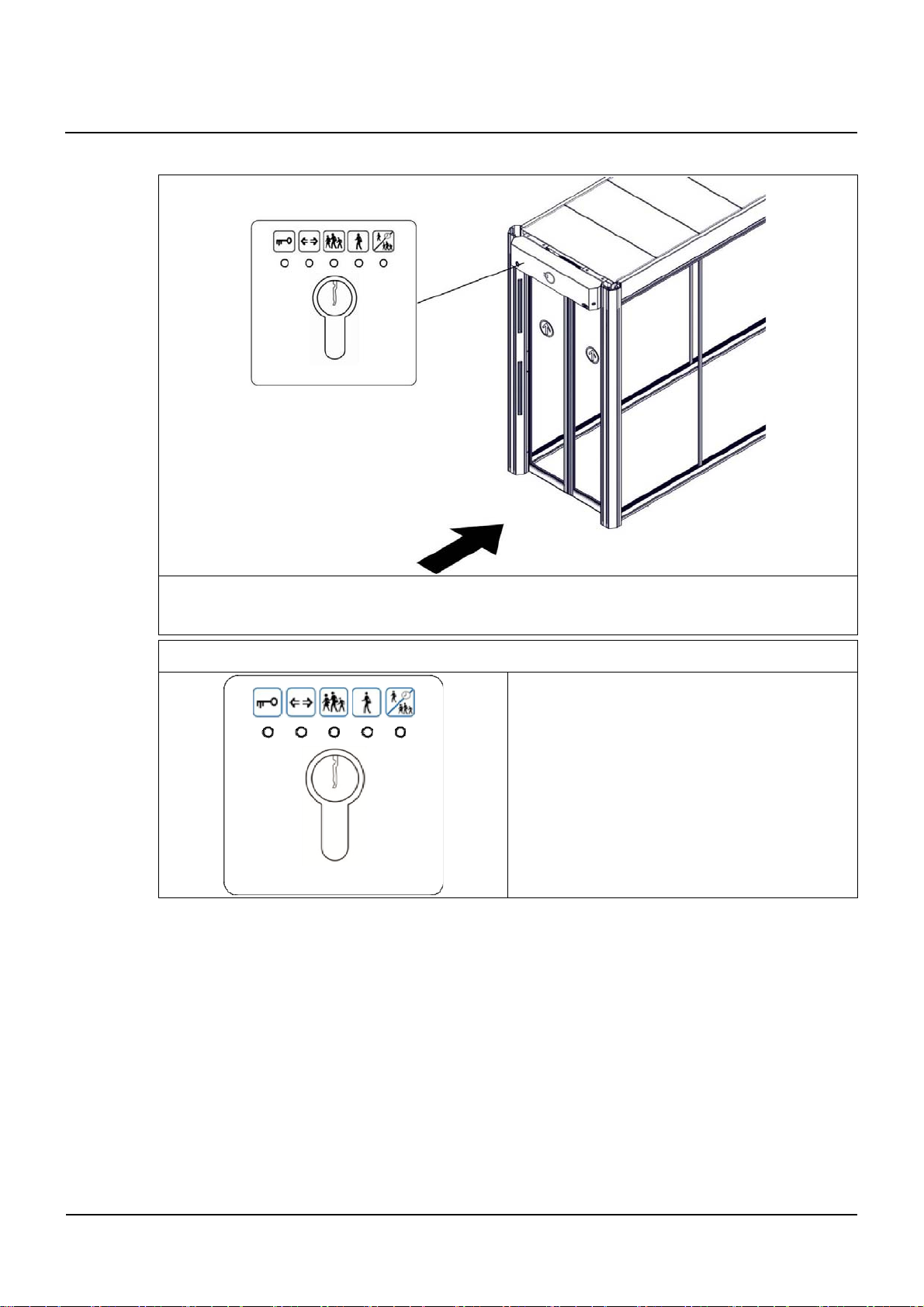
Control panel position
The control panel BDE-S (for the selecting the operating mode) is located in the on the cladding be-
hind the cover of the entrance door.
The control panel BDE-S for the FlipFlow
This control panel is used to switch between the
various operating modes of the FlipFlow.
Switching to the CLOSED/LOCKED mode also
performs a manual reset of the system.
FlipFlow traffic lights
Signaling depends on the operating mode selected and the choice of options ordered. The standard
basic version of the FlipFlow is equipped with a set of red, yellow and green LED-Strips on the en-
trance door. How the LED-Strips operate is explained under the various operating modes of the
FlipFlow.
3.2
3.3
Other manuals for FlipFlow TWIN
2
Table of contents
Other Record Turnstile manuals


Popular Turnstile manuals by other brands


DSI
DSI DST-80 Service & installation manual

OZAK
OZAK VP-125 Assembly, Installation and Maintenance Handbook

Automatic Systems
Automatic Systems SMARTLANE SL 90X Technical manual

Alvarado
Alvarado MT Installation & maintenance instructions

JKDC SECURITY
JKDC SECURITY JKDC-100C user manual

Alvarado
Alvarado SU5000 quick guide


