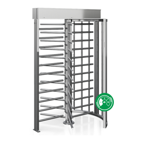
Turnstiles DS7200 User manual

Please read and follow theinstallation instructions before
operating the equipment, and save the instructions for future reference orfor
future users.
Speed Gate Turnstile
User Manual

Speed Gate Turnstile User Manual
TABLE OF CONTENTS
1. Brief introduction..........……………
2. Functional features…………………
3. Main specifications……………………
4. Product structure and working principle…………
4.1 Electronic control system of channel gate………………
4.2 Operating principle of the system…………………………
5. Equipment installation………………………………
5.1. Equipment installation instructions………………………
6. Device function debugging…………………………
6.1 Key description……………………………………………
6.2 Function parameter setting………………………………
6.3 Main board wiring instructions……………………………
7. Common fault handling……………………………
8. Customer service……………………………………

Speed Gate Turnstile User Manual
1. Brief Introduction
The Speed gateturnstile has undergone years of R&D. The device
integrates mechanical, electronic, microprocessor control and various
reading and writing technologies.
The appearance of the equipment hasstainless steel plate laser welding
molding, beautiful and generous shape, rust-proof, durable, and external use of
standard electrical interface, bar code card, ID card, IC card and other card readers
can be easily integrated in the equipment, to provide civilized and orderly access
for personnel, but also can eliminate illegal personnel access; In addition, the
system is specially designed to meet the fire requirements of the function, in the
case of emergency, to ensure that the passage unimpeded, convenient personnel
timely evacuation;
2. Functional Features
1) With zero self-check function, convenient for users to maintain and use;
2) Illegal entry with alarm function;
3) Anti-impact function, when no signal is received, the door will automatically lock
or alarm;
4) Infrared anti-clamping function;
5) It has the automatic reset function of timeout. After the pedestrian reads the valid
card, if the pedestrian fails to pass within the specified time, the system will
automatically cancel the pedestrian's permission to pass;
6) Unified standard external electrical interface, which can be connected with a
variety of card readers, and can achieve remote control and management through
management computer.

Speed Gate Turnstile User Manual
3. Main specification
Frame material
304 stainless
steel
Input power AC220V/110V, 50/60Hz
Working voltage 24 V DC Drive motor 24V dc motor
Working temp. -20℃- 75℃Relative
humidity
relative humidity ≤90%,
no condensation
Opening signal Relay dry
contact signal
Communication
interface RS232
Application Indoor Traffic speed 35-40 people/min
4. Product Structure and Working Principle
4.1. Electronic control system of channel gate
The electronic control system consists of card reader, main control board, infrared
sensor, direction indicator board, alarm, transformer, etc.
Card reader (self-provided): after reading the information on the card and judging
and processing, send the application pass signal (switch signal) to the main control
board.
Master control board: the control center of the system, which receives signals

Speed Gate Turnstile User Manual
from the card reader and infrared sensor, makes logical judgment and processing
of these signals, and then issues execution commands to the direction indicator,
motor, counter and alarm.
Infrared sensor: detect the pedestrian position and play the role of safety
protection.
Direction indicator light: displays the current status of the channel and guides
pedestrians to pass through the channel in a safe and orderly manner.
Alarm: when the system detects pedestrians entering the passage illegally, it will
send out an alarm.

Speed Gate Turnstile User Manual
Alarm
Name Function
1
Entrance guard system
IC/ID card access control, fingerprint device,
face recognition, QR code device,
gate opening signal on the control board of
gate machine, remote control,
button to open the door (optional)
2 Control board
The control center of the system,
which receives signals from the card reader
and infrared sensor, and makes logical judgment
and processing of these signals,
and then sends out execution commands to the
direction indicator, motor, counter and alarm.
3 Infrared sensor Detect the position of pedestrians and safety protection
4 Direction indicator Display the current traffic sign status of the gate
and guide pedestrians through the gate
5 Alarm (speaker)
When the system detects a pedestrian illegally entering
the passageway, it gives an alarm.
6 Motor Drive the mechanism
7 power supply Switch Control panel power supply

Speed Gate Turnstile User Manual
4.2. Operating principle of the system
A). Turn on the power and the system will enter the working state after 3 seconds.
B). When the card reader reads an effective card, the peal speaker will make a
pleasant sound to remind the pedestrian that the card is read successfully. At the
same time, it will judge and process the information read from the card and send an
application signal to the main control board.
C). The main control board receives the signal from the card reader and infrared
sensor, and after comprehensive processing, sends an effective control signal to
the direction indicator and the motor, so that the direction indicator sign turns into a
green arrow pass sign. At the same time, the brake sends a setting voice, the main
control board controls the motor operation, and the gate opens to allow pedestrians
to pass.
D). after the pedestrian passes through the channel according to the direction
indicator sign, the infrared sensor senses the whole process of the pedestrian
passing through the channel and continuously sends signals to the main control
board until the pedestrian has passed through the channel completely;
E). If the pedestrian forgets to read the card or reads the invalid card to enter the
channel, the system will forbid the pedestrian to pass, and will issue a voice alarm,
until the pedestrian exits the channel, the alarm will be lifted; Reread valid
chi-square allowed pass.
5. Equipment Installation
Attention: During installation and construction, relevant circuits should be
disconnected to ensure that all circuits are correct before energizing.
5.1. Equipment installation instructions

Speed Gate Turnstile User Manual
1. Prepare the equipment installation tools and check the accessories according to
the packing list.
2. After finishing the foundation surface of the installation equipment, arrange the
equipment well.
3. After the hole location is determined, drill the hole and embed the anchor bolt or
expansion bolt of M12.

Speed Gate Turnstile User Manual
4. Put the strong electric cable and weak electric cable through 3/4 "PVC pipe and
bury them in cement to the corresponding position.
5. Open the case door, select one of the equipment as the reference (it is better to
choose the middle one as the reference), align the bolt hole of the machine seat
with the corresponding anchor bolt, and tighten the nut first.
6. Refer to the wiring diagram, connect the power line and control line well, and
connect the system ground wire protection.
7. After check, if the equipment status is normal, the following function debugging
can be carried out.
8. Check the mains wiring according to the wiring diagram, check the power wiring
and other wiring of the whole equipment is correct, the debugging can be done
after confirmation.
6. Equipment function debugging
6.1 Key description
Long press "menu” for 3 seconds -- to enter the L-series, press "up” enter L-2...
Press "ok" again to enter the H-series, press up or down to make adjustment, press
"menu key" to return and save, and press "ok" to exit the setting option.
Long press "menu key" for 3 seconds -- enter l-1 and press "down key" plus value
d-2...

Speed Gate Turnstile User Manual
Press "ok" again to enter the h-series adjustment value "up key - plus value" "down
key - minus value", press "menu key" to return and save, and press "ok" to exit the
setting option
6.2 Function parameter setting
<L-1 >Opening time of entrance and exit (default 6 seconds)
Setting the opening time of swinging door after swiping card authorization.
<L-2 >Set working method
0: swipe card from left & right
1: left infrared sensor, right swipe the card
2: right infrared sensor, left swipe the card
3: infrared sensor left and right
< L-3 > Delay closing time
Set closing time after pedestrian pass the channel (default: 0.2s), can be set from
0-50s
< L-4 > Left pass voice speaker
Default: 1: Welcome
Voice speaker number code from 0 to 18
For example: 0: Welcome, 1: Welcome back
< L-5 > Right pass voice speaker
Default: 15: Safe Travel
Voice speaker number code from 0 to 18
For example: 0: welcome, 1: Welcome back
< L-6 > infrared stack time (second)

Speed Gate Turnstile User Manual
Set the time setting for sensing multiple infrared simultaneously (default 3/ s)
< L-7 > opening direction when power off
After setting the gate opening direction when power off
Default: 0 to the left, according to the site
0: open to the left
1: open to the right
< L-8 > trespassing alarm
Default: 0: trespassing, please swipe the card
1: ticking sound
< L-9 > Entrance and exit memory function, continuous swipe card
Set up group ticket, continuous swipe mode
default:0: without memory function
0: without memory function, 1: with memory function
< L-10 > Infrared anti-pinch
Set when pedestrians and other circumstances touch off the anti-clip infrared,
swing door will close or not (default: 1 means: close)
0 represents: open, 1 represents: close
< L-11 > Infrared sensor quantity
Default: 0:4 pairs,
0: 4 pairs1: 6pairs
< L-12 > speaker volume
Set the speaker volume, (value: 0-15), 0 is min volume, 15 is max volume.
Default: 15
< L-13 > voice message test
After entering the voice test, the gate will automatically broadcast all the voices to

Speed Gate Turnstile User Manual
make sure the entire voice messages are normal and convenient for users to
quickly understand which voice options are included. For example: exit the voice
test mode, please press the "OK" key on the motherboard.
< L-14 > aging test
After entering the aging mode, the gate will automatically open and close the door
and enter the aging mode.
Such as: exit aging mode, please press the menu key.
< L-15 > Main motor type selection
Select the corresponding value according to different brands of motors, the default
value is 1, do not change at will.
< L-16 > Main motor type selection
Select the corresponding value according to different brands of motors, the default
value is 1, do not change at will.
< L-17 >Reverse entry gate setting
0 means no close, 1 means close, and default value 0, do not change at will.
< D-1 > Zero setting of closing position
When pedestrian gate close, the channel is not aligned, nor in the middle position.
You can adjust the channel position by enter the parameter setting according to the
voice prompt to manually move the pendulum door to the desired position, press
“ok” to save.
< D-2 > left open position setting
When the gate open not in desired position, you can adjust the channel position by
enter the parameter setting according to the voice prompt to manually move the
pendulum door toward the left direction to the desired position, press ok to save
< D-3 > right open position setting

Speed Gate Turnstile User Manual
When the gate does not open in desired position, You can adjust the channel
position by enter the parameter setting according to the voice prompt to
manually move the pendulum door toward the right direction to the desired
position, press ok to save
< D-4 > Open speed setting
Set open speed, value from 1-10, 1 is the fastest speed, 10 is slowest speed.
< D-5 > Gate type
Set type;swing gate / flap gate, ( 0: swing gate, 1: flap gate). This parameter isset
as factory default. Do not change
< D-6 > Theclutch
According to the corresponding drive Settings of brake configuration, "0 is no
clutch, 1: clutch" this parameter is set according to the factory default. Do not
change.
< D-7 > Resistance rebound Mode
When a pedestrian pass the channel, and hit by the gate, it will bounce back or
keep closing, default setting is 0.
0: Hit the pedestrian then bounce back then keep open1: hit the pedestrian, stop for
seconds, and then keep open
< D-8 >Counter strength (master)
When the swinging door is in the closed non-working state, the reverse force can
be adjusted when the swinging door is forced open by the external force. The
larger the value, the greater the force ( value 1-20), default:14
< D-9 > Reset time
Setting the time interval between swiping card 《value 0.1- 10》default:0.1
< D-10 > Buffer strength from gate closing (master)
The buffer strength is adjusted, the larger the value, the faster the closing speed

Speed Gate Turnstile User Manual
and the greater the vibration. The smaller the value, the slower and more stable the
closing speed. Value 50-150 default value: 35
< D-11 > Motor strength (master)
Motor strength setting, the larger the value is, the greater gate closing strength and
the greater the vibration. Value : 1-100, default is 40.
< D-12 >Buffer strength from gate closing (slave)
The buffer strength is adjusted, the larger the value, the faster the closing speed
and the greater the vibration. The smaller the value, the slower and more stable the
closing speed. Value 50-150 default value: 35
< D-13 > Motor strength (slave)
Motor strength setting, the larger the value is, the greater gate closing strength and
the greater the vibration. Value : 1-100, default is 40.
< D-14 > Power supply
Adjust the power of the main board power "value 1-10" default value: 6
Do not change it at will.
< D-15 > Speed to find zero position
After the gate connected to power, the speed to find the zero speed, the bigger the
value is, the faster the speed, the value is 1-10, default is 5, don’t change it at will
< D-17 > physical pinch sensitivity
The sensitivity setting when the gate hit pedestrian or in the face of obstacle, the
smaller the value is , the higher sensitivity . Note: this setting only be effective when
the Resistance rebound Mode is set. Value: 1-99, default is 75.
< D-18 > Physical clamping current time

Speed Gate Turnstile User Manual
The sensitivity setting when the gate hit pedestrian or in the face of obstacle, the
smaller the value is , the higher sensitivity . Note: this setting only be effective when
D17 was set . Values 1-99 default value: 10
< D-19 > KP
Set motor parameters "value 1-999" default value: 160 do not change at will
< D-20 > KI
Set the motor parameter "value 1-200" default value: 0 do not change at will
< D-23 > Physical clamping reaction time
This adjustment needs to contact the manufacturer's technical staff "value 1-100"
default value: 0 do not change at will.
< D-26 > counter strength (slave)
When the swinging door is in the closed non-working state, the reverse force can
be adjusted when the swinging door is forced open by the external force. The
larger the value, the greater the force ( value 1-20), default:14

Speed Gate Turnstile User Manual
6.3 Main board wiring instructions
Motor wiring (yellow, blue, green wire motor)
Motor
Name
Color
PCB screen print
Motor phase
U
yellow(thick)
U
V green(thick) V
W blue(thick) W
Motor Hall
GND black(thin) GND
Hu yellow(thin) EU
Hv green(thin) EV
Hw
blue(thin)
EW
5V+
red(thin)
5V
Motor wiring (white, blue and green)
Motor
Name
Color
PCB screen print
Motor phase
W
white(thick)
U
U
blue(thick)
V
V
green(thick)
W
Motor hall
GND black(thin) GND
Hu white(thin) EU
Hv blue(thin) EV
Hw green(thin) EW
5V+ red(thin) 5V

Speed Gate Turnstile User Manual
7. Common fault handling
7.1. After swipe a card or Face recognition, the gate won’t open or
none react.
Check the open signal wire connection was right or loose, manually press the
motherboard button or short connection to see whether it will open. If manual
operation won’t work, disconnect the power and reboot, the motor works, then need
to replace the main board.
7.2. The gate keep opening and closing
Adjust D-23 to 50
7.3. Power off and reboot, the master gate stay open.
To recheck whether the synchronization line is connected well, you can unplug the
terminal to reconnect, check and test whether synchronous communication network
line is normal, if the normal side of the network line needs to replace the
motherboard.
7.4. After swipe a card, master gate open, slave gate won’t open
1)Check if the entire infrared sensors are working, when there is no pedestrian in
the channel, the indication light of infrared sensor in the master gate is off, it means
the infrared sensor is normal, if the light is on, it means the infrared is in failure or
not in alignment.

Speed Gate Turnstile User Manual
2)Cut the power supply, and reboot, see if the masterand slave motor can work
normally, if not, replace the main board, if still notwork, replace the motor.
7.5. Swing arm isout of sync when opening or closing the door
after swiping the card
Adjust D-10 and D-12, which arm is slower, increase the value
7.6. Swing arm hitsthe gate frame
1)check the swing arm loose or not
2)manual reset the left open position, right open position and closing position. 3)
check if any parts is loose in the motor and drive system, If above all are normal, it
needs to replace the drive.
7.7. When E-1 or E-2 appears in digital tube of main board
SetL-15,L-16 value to 1

Speed Gate Turnstile User Manual
8. Customer service
We are very happy to help you in the future when you encounter problems or
product defects, if the use or operation is not clear, please timely contact the
after-sales service staff.
Warranty Card
(Warranty: 3 years)
Order Date: Product Name: Product Model:
Customer Country:
Company Name:
Email:
Fault descriptions with photo/video:
Table of contents
Other Turnstiles Turnstile manuals

Turnstiles
Turnstiles HZ-FHTS05 User manual

Turnstiles
Turnstiles MPW 112 Technical manual

Turnstiles
Turnstiles TPW-321ASP User manual

Turnstiles
Turnstiles AG Series User manual
Turnstiles
Turnstiles OST Instruction Manual

Turnstiles
Turnstiles HZ-FHTS03 User manual

Turnstiles
Turnstiles HZ-SLBS02 User manual

Turnstiles
Turnstiles HZ-FHTS04 User manual
Turnstiles
Turnstiles OMD22 User manual
Turnstiles
Turnstiles HS400 Series User manual