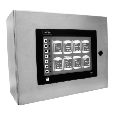
red lion BFD User manual

ForSalesandSupport,ContactWalkerEMD•Toll-free:(800)876-4444•Tel:(203)426-7700•Fax:(203)426-7800•www.walkeremd.com
1
DESCRIPTION
The BFD is a large (38.5" x 19") LED display (128 x 64 pixel resolution)
which is driven from the RS485 port of a G3. The BFD is built using 32 display
boards in an 8 column by 4 row configuration. When used with a G303, the BFD
will display the contents of the current G3 page. When used with larger G3s, the
desired information is selected by using a “display primitive” on the current G3
page. Multiple BFDs can be driven from a single G3 (see Using Multiple BFDs
with a single G3). The exact number is dependent upon the lengths of the
individual wiring runs. Contact Red Lion Tech Support for more info.
The display is housed in a welded steel enclosure and the display window
(0.118" thick red acrylic) is sealed to the enclosure using a gasket and bezel
strips. The gasketed rear panel is bolted to the enclosure. The ventilation slots
and internal fan are designed to provide adequate cooling in a normal industrial
environment. The enclosure is designed to hang from an overhead support.
The BFD enclosure can be easily converted for indoor NEMA 4 operation
using the optional BFD NEMA 4 conversion kit. The kit includes a sealed cover
plate (to plug the vent hole), an external “cabinet cooler” (to replace the internal
fan) and a DIN-rail mounted power supply to operate the “cabinet cooler”.
Power to the BFD is provided by a universal AC input power supply. The AC
power and the G3 RS485 cable enter the enclosure thru separate conduit fittings.
AC power connects to the power supply via a removable 3 position terminal
block. The RS485 signal connects to the communication board via either an
RJ45 modular plug or a removable 2 position terminal block.
SAFETY SUMMARY
All safety related regulations, local codes and instructions that appear in the
literature or on equipment must be observed to ensure personal safety and to
prevent damage to either the instrument or equipment connected to it. If
equipment is used in a manner not specified by the manufacturer, the protection
provided by the equipment may be impaired.
CONTENTS OF PACKAGE
- G3BFDM Display
- Hardware kit including #8-32 screws & #8 flat washers for the rear cover;
air filter, retainer and this instruction booklet.
- Mounting kit including eyebolts, locknuts, conduit fittings & seals & hole
plugs
ORDERING INFORMATION
Notes:
1. NEMA Type 4 protection is only available as a field (customer) installed
option. Even though the use of this conversion kit provides the BFD with
NEMA Type 4 protection, it is not intended to be operated outdoors in
direct sunlight.
2. Visit www.redlion.net/g3 for additional features, options and drivers for
your G3.
3. Use this part number to purchase Crimson 2.0 on CD with a printed
manual, USB cable, and RS-232 cable. Otherwise, download from
http://www.redlion.net/g3
MODEL BFD - BIG FLEXIBLE DISPLAY
Bulletin No. BFD-A
Drawing No. LP0591
Released 6/05
Tel +1 (717) 767-6511
Fax +1 (717) 764-0839
www.redlion.net
MODEL NO. DESCRIPTION PART NUMBER
Crimson
BFD
SFCRM200
G3BFDNEM
G3BFDM00
CBL
G3BFDFIL
G3BFDDSP
CBLRLC04
zLARGE 38.5" (977.9 mm) X 19" (482.6 mm) RED LED DISPLAY
WITH 0.2" DIAMETER PIXELS; 128 X 64 DOT RESOLUTION
zDISPLAYS THE INFORMATION FROM ANY G3 TO THE PLANT
FLOOR
zCONNECTS DIRECTLY TO THE RS485 PORT OF A G3
zFIELD REPLACEABLE DISPLAY BOARDS
zREPLACEABLE FAN FILTER
zFLEXIBLE 4 EYEBOLT MOUNTING
zUNIVERSAL AC POWER (100 - 240 VAC, 50 / 60 HZ)
zOPTIONAL NEMA 4 COOLING KIT AVAILABLE
Crimson 2.0 for G3 3
Big Flexible Display NEMA 4 Kit
Big Flexible Display
CAUTION: Read complete
instructions prior to installation
and operation of the unit.
CAUTION: Risk of electric shock.
Replacement Fan Filter
Replacement Display Module
10-foot RS485 cable for communications between
G3 and G3BFD

ForSalesandSupport,ContactWalkerEMD•Toll-free:(800)876-4444•Tel:(203)426-7700•Fax:(203)426-7800•www.walkeremd.com
2
1. POWER: Universal AC input (100 - 240 VAC 50/60 Hz); 2.0 A @ 120 VAC;
1.0 A @ 240 VAC.
Power connection via removable three position terminal block. The 5 VDC
supply to the BFD display boards is protected by two in-line 25 A automotive
blade type fuses in the wiring harness (Littelfuse #257.025 or equivalent).
2. DISPLAY: 128 x 64 resolution using 0.2" (5.08 mm) diameter red LED
pixels. Overall display measures 38.5" (977.9 mm) x 19" (482.6 mm).
3. COMMUNICATIONS: Connects to the host G3 thru RS485 port via either
RJ45 or a removable 2 position terminal block; 115,200 baud, 8 bit, 1 stop
bit, no parity. The RS232 ports (either the COMMs or PGM ports) may also
be used with the appropriate RS232 to RS485 converter. Note that the RS232
and RS485 ports provided by the Expansion card are not currently supported.
Isolation for communications: 2500 Vrms
Isolation for common: 1000 VDC for 60 seconds.
4. ENVIRONMENTAL CONDITIONS:
Operating Temperature : 0 - 50°C
Storage Temperature : -10 - 60°C
Operating and Storage Humidity: 80% maximum relative humidity (non-
condensing) from 0 to 50°C
Altitude: Up to 2000 meters
5. CERTIFICATIONS AND COMPLIANCES: Contact your Red Lion
Controls distributor for more information.
6. CONSTRUCTION: Welded steel enclosure with sealed red acrylic display
window. Removable gasketed rear cover attaches with bolts. Welded mounting
blocks to receive 3/8" (9.53 mm) eyebolts (provided) for suspension.
7. MOUNTING REQUIREMENTS: Suspend from overhead truss or other
suitable structure using cable or chain capable of supporting the BFD.
Suspension eyebolts and locknuts are included. See “Mounting Instructions”
for more info. Refer to local safety codes for additional requirements.
8. WEIGHT: 117 lbs. (53.07 Kg)
INSTALLING THE BFD
SPECIFICATIONS
DIMENSIONS In inches (mm)
MOUNTING INSTRUCTIONS
This display is designed to be suspended from a ceiling truss or other suitable
structure capable of supporting the BFD. Extreme caution should be exercised
when hanging the display to provide for the safety of personnel. Install ALL
four eyebolts (provided) into the holes of the mounting blocks (see Figure 1).
The eyebolts should be installed so that enough of the threads are exposed at the
bottom of the mounting block that the four locknuts (provided) can be fitted
with a minimum of one thread exposed (see Figure 1). Note that the eyebolt
must be orientated so that the load is applied in the same plane as the loop of
the “eye” (see Figure 1).
The angle of the display can be adjusted by altering the length of the front
suspension cables (or chains) relative to that of the rear cables (or chains).
Further adjustment is possible by threading the eyebolt farther into the
mounting block as shown. It is critical that the minimum thread exposure shown
in Figure 1 is maintained.
BFD with NEMA 4 Option (G3BFDNEM)
BFD
FIGURE 1
Note: Loads must always be applied to each eyebolt in
the plane of the eye, not to some angle to this plane.

ForSalesandSupport,ContactWalkerEMD•Toll-free:(800)876-4444•Tel:(203)426-7700•Fax:(203)426-7800•www.walkeremd.com
3
POWER CONNECTIONS
Access to the electrical connections is provided by removing the rear cover of the BFD. The BFD enclosure
provides four holes to receive 2 - ½ inch conduit fittings (two on the top of the enclosure and two on the right side
of the enclosure as viewed from the rear of the enclosure). Install the conduit fittings and water tight conduit seals
in the desired positions (place the indicated surface of the seal against the BFD enclosure to guarantee a proper
seal. See Figure 2) and install the hole seals into the remaining holes.
The protective conductor terminal is bonded to conductive parts of the equipment for
safety purposes and must be connected to an external protective earthing system.
Using one of the conduit fittings, connect the AC power to one of the available
removable terminal blocks on the DIN rail mounted wiring assembly. A separate earth
grounding point is provided. The AC input must be able to supply the BFD with 2.0 A
@ 120 VAC 60 Hz or 1.0 A @ 240 VAC 50 Hz. Be certain the chassis of the BFD is
properly earth grounded and correctly protected with circuit breaker protection before
applying power to the unit. Refer to Figure 3.
COMMUNICATIONS CONNECTION
The RS485 cable from the G3 should enter the enclosure using the conduit
fitting not used by the power connections and should be connected to the BFD
communications board via either the 2 position removable terminal block or the
RJ45 jack. See Figure 3.
FIGURE 3
FIGURE 4
FAN FILTER INSTALLATION &
REPLACEMENT
The fan filter and filter retainer are located in the BFD Hardware Pack. Place
the filter into the retainer. The retainer will snap onto the filter mounting plate
(which is attached to the BFD case. See Figure 4). This filter can be cleaned by
rinsing it with water and allowing it to dry.
FIGURE 2

ForSalesandSupport,ContactWalkerEMD•Toll-free:(800)876-4444•Tel:(203)426-7700•Fax:(203)426-7800•www.walkeremd.com
4
1. Turn off AC power to the BFD at the circuit breaker.
2. Remove the rear cover of the BFD. DO NOT REMOVE THE FRONT WINDOW IN
AN ATTEMPT TO GAIN ACCESS TO THE INSIDE OF THE BFD.
3. Disconnect the fan cable assembly (Figure 5a).
4. Remove the 4 kep nuts holding the fan in place (Figure 5b). These parts are no longer
needed.
5. Holding the gasket and the blank vent cover plate (Figure 6a) in place to
cover the fan opening, insert and tighten 8 screws (all supplied as
part of the NEMA 4 kit). Care must be taken during this step
to assure the integrity of the NEMA 4 seal.
6. Remove the 8 screws holding the vent plate (Figure 5c).
Discard the vent plate.
7. Insert the cooling assembly from the outside so that the
fans are positioned up and the wires are inside the
enclosure (Figure 6b). Note that the gasket must be placed
between the assembly flange and the enclosure. Insert and
tighten the 8 screws. Care must be taken during this step to
assure the integrity of the
NEMA 4 seal.
8. Install the NEMA 4 power
supply onto the din rail strip
inside the BFD enclosure
(Figure 6c).
9. Connect the 3 position removable
terminal block (Figure 6d) from the
NEMA 4 power supply to the open
socket (Figure 3b) on the DIN rail
wiring assembly.
10. Connect the 2 wire cable assembly from the
NEMA4 power supply to that of the cooling assembly (Figure 6b).
11. Replace the rear cover, assuring that the seal is in good condition.
12. Turn on AC mains power to the BFD at the circuit breaker. The
NEMA 4 cooling assembly fans will run continuously.
PROGRAMMING THE DISPLAY
When programming the G3 using Crimson 2.0, the display information for the
BFD is selected by using the “display primitive” on the active display page. Any
information contained within the primitive's borders will be sent to the BFD.
BFD SOFTWARE DRIVER
The “Big Flexible Display” driver must be selected in Crimson 2.0 under the
“Red Lion” drivers. A G3 unit must be used with this driver. The driver can be
used on either the RS232 or RS485 port of the G3. However, only a RS485 port
is included on the BFD. If RS232 is used an RS232 to RS485 serial converter
must be used. Red Lion offers the ICM5 for just such tasks.
Note the “Big Flexible Display” driver is considered a master protocol.
Therefore the other communications port can be used for another master
protocol driver, but cannot be used for a slave protocol driver.
CRIMSON SOFTWARE
The BFD requires the use of Crimson 2.0 build 191 or later. The latest
version of the software is always available from the website, and updating your
copy is free.
BFD COMMUNICATIONS WITH A G3
FIGURE 5
FIGURE 6
INSTRUCTIONS FOR INSTALLING THE OPTIONAL NEMA 4 COOLING KIT

ForSalesandSupport,ContactWalkerEMD•Toll-free:(800)876-4444•Tel:(203)426-7700•Fax:(203)426-7800•www.walkeremd.com
5
Although most of the expected applications for the BFD use a single BFD and
a G3, the design allows some flexibility for those applications where more than
one BFD is required.
Up to 7 BFDs maybe connected to a single serial port, each one identified by
a unique address in the range 0..6. The address is set by DIP switch positions 1,
2 & 3, eg, to set BFD address to 6, set 1 and 2 ON, and 3 OFF. Note that each
of the 32 display boards in the BFD will have to have these DIP switches set for
the same unit address. Power must be cycled OFF, then ON so that the new DIP
switch values will take effect.
The remote display primitive describes a region of the current Display page
to be rendered on a BFD. The configuration of each “remote display primitive”
includes the logical serial port that the BFD is connected to, and the unit address
of the BFD as set by it's DIP switches. By placing more than one “remote
display primitive” on the G3’s Display Page, each BFD can be made to display
different information.
A BFD may show the same information as another BFD on the same serial
port by simply setting the unit addresses the same on both units. To show the
same information on BFDs on different serial ports, simply overlay the remote
display primitives on the current Display page and configure the logical port and
BFD address as appropriate.
The display information from the G3 must be passed to each BFD. The
easiest way to do this is to wire to the unused RS485 connector in the first BFD
(See Figure 3a) and connect it to the second unit (daisy chain wiring). Power for
each unit can be wired as normal.
USING MULTIPLE BFDS WITH A SINGLE G3
MULTIPLE BFDs DISPLAY THE SAME INFORMATION
REPLACING A DISPLAY BOARD
The display boards are held in place by a display frame assembly, which is
built from nine aluminum display rail extrusions. The extrusions have a slot on
each side to receive the PC board edge of the display boards. The boards simply
slide into place. A male right angle connector on the top side of the board mates
with a female connector of the board above it, thus, passing the power and signal
from the top board to the bottom board. In normal operation, the display frame
is fastened to the enclosure using 4 nuts (Figure 8a). However, these nuts can be
removed to service the display, if required. The display frame has a pivot point
along the bottom edge, which allows the top edge of the frame to tilt outside the
enclosure, providing access to the top display boards. Display boards are easily
removed by disconnecting the appropriate wiring connection from the top board
(Figure 7b), separating the boards and sliding them out the top of the frame
assembly (Figure 8).
Each display board has a 8 circuit dip switch which is used to set its location
address. This address is determined by the board’s physical location within the
BFD display (Figure 7a).
1. Turn off AC mains power to the BFD at the circuit breaker.
2. Remove the rear cover of the BFD. Do Not Remove The Front Window To
Attempt To Gain Access To The Inside Of The BFD.
3. Remove the AC mains 3 position removable terminal block (Figure 3c).
Disconnect the main wiring harness connector (Figure 10a) from the power
supply. Disconnect the fan cable assembly (Figure 5a) or the NEMA 4 cooler
cable assembly (Figure 6b). Disconnect the RS485 cable to the G3 (Figure
3a).
4. Remove the 6 #8 kep nuts which fasten the power supply subassembly to the
enclosure. Remove the power supply subassembly (Figure 8b).
5. Remove the NEMA 4 Cooling kit (if applicable - See “Instructions for
installing the optional NEMA 4 cooling kit”).
6. Remove the 4 #8 kep nuts which fasten the display frame assembly to the
front of the enclosure (See Figure 8a). The display frame assembly will now
tilt back to allow access to the display boards.
7. Lift off the display frame top stop bracket (See Figure 8).
8. Locate the column of display boards with the faulty display board and remove
the two wiring cables (which connect the main wiring harness to the top
display board, Figure 7b).
9. Remove the appropriate board (See Figure 8). Note the DIP switch setting
(Figure 7a) on the old board.
10. Change the DIP switch setting on the replacement board and install the new
board in the same position as the old board. Make sure that the board-to-board
pins are properly aligned.
11. Re-connect the two wiring bundles observing the proper orientation of the
connectors (Figure 7b).
12. Repeat steps 1 through 7 in reverse order.
13. Note that if the DIP switch setting on a board must be changed (due to
incorrect setting), the power to the unit must be cycled in order for the change
to take effect.
TROUBLESHOOTING
FIGURE 7


ForSalesandSupport,ContactWalkerEMD•Toll-free:(800)876-4444•Tel:(203)426-7700•Fax:(203)426-7800•www.walkeremd.com
6
OTHER DISPLAY PROBLEMS
If the BFD display does not look correct (as compared to that of the G3), re-
check the DIP switch settings of the BFD display boards. Cycle the power to the
BFD if any changes are made to the DIP switches.
If either the left or the right half of the display does not operate, check and
replace (if necessary) the in-line fuse in the wiring harness (Figure 10b).
TROUBLESHOOTING YOUR BFD
If for any reason you have trouble operating, connecting, or simply have
questions concerning your new BFD, contact Red Lion’s technical support.
EMAIL: [email protected]
Web Site: http://www.redlion.net
FIGURE 8
REPLACING A DISPLAY BOARD (Cont’d)

ForSalesandSupport,ContactWalkerEMD•Toll-free:(800)876-4444•Tel:(203)426-7700•Fax:(203)426-7800•www.walkeremd.com
7
WIRING DIAGRAM
FIGURE 10

ForSalesandSupport,ContactWalkerEMD•Toll-free:(800)876-4444•Tel:(203)426-7700•Fax:(203)426-7800•www.walkeremd.com
Red Lion Controls
20 Willow Springs Circle
York PA 17402
Tel +1 (717) 767-6511
Fax +1 (717) 764-0839
Red Lion Controls AP
31, Kaki Bukit Road 3,
#06-04/05 TechLink
Singapore 417818
Tel +65 6744-6613
Fax +65 6743-3360
Red Lion Controls BV
Basicweg 11b
NL - 3821 BR Amersfoort
Tel +31 (0) 334 723 225
Fax +31 (0) 334 893 793
LIMITED WARRANTY
The Company warrants the products it manufactures against defects in materials and workmanship
for a period limited to two years from the date of shipment, provided the products have been stored,
handled, installed, and used under proper conditions. The Company’s liability under this limited
warranty shall extend only to the repair or replacement of a defective product, at The Company’s
option. The Company disclaims all liability for any affirmation, promise or representation with
respect to the products.
The customer agrees to hold Red Lion Controls harmless from, defend, and indemnify RLC against
damages, claims, and expenses arising out of subsequent sales of RLC products or products
containing components manufactured by RLC and based upon personal injuries, deaths, property
damage, lost profits, and other matters which Buyer, its employees, or sub-contractors are or may be
to any extent liable, including without limitation penalties imposed by the Consumer Product Safety
Act (P.L. 92-573) and liability imposed upon any person pursuant to the Magnuson-Moss Warranty
Act (P.L. 93-637), as now in effect or as amended hereafter.
No warranties expressed or implied are created with respect to The Company’s products except those
expressly contained herein. The Customer acknowledges the disclaimers and limitations contained
herein and relies on no other warranties or affirmations.
This manual suits for next models
2
Table of contents
Other red lion Monitor manuals

red lion
red lion MDI User manual

red lion
red lion LDA Series User manual

red lion
red lion PAX User manual

red lion
red lion LD User manual

red lion
red lion EPAX-5 Instruction Manual

red lion
red lion LPAX Series User manual

red lion
red lion LD Series User manual

red lion
red lion APLHV User manual

red lion
red lion LPAX User manual

red lion
red lion APLSP User manual