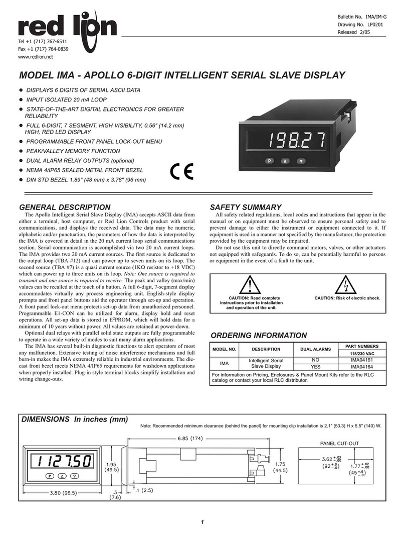
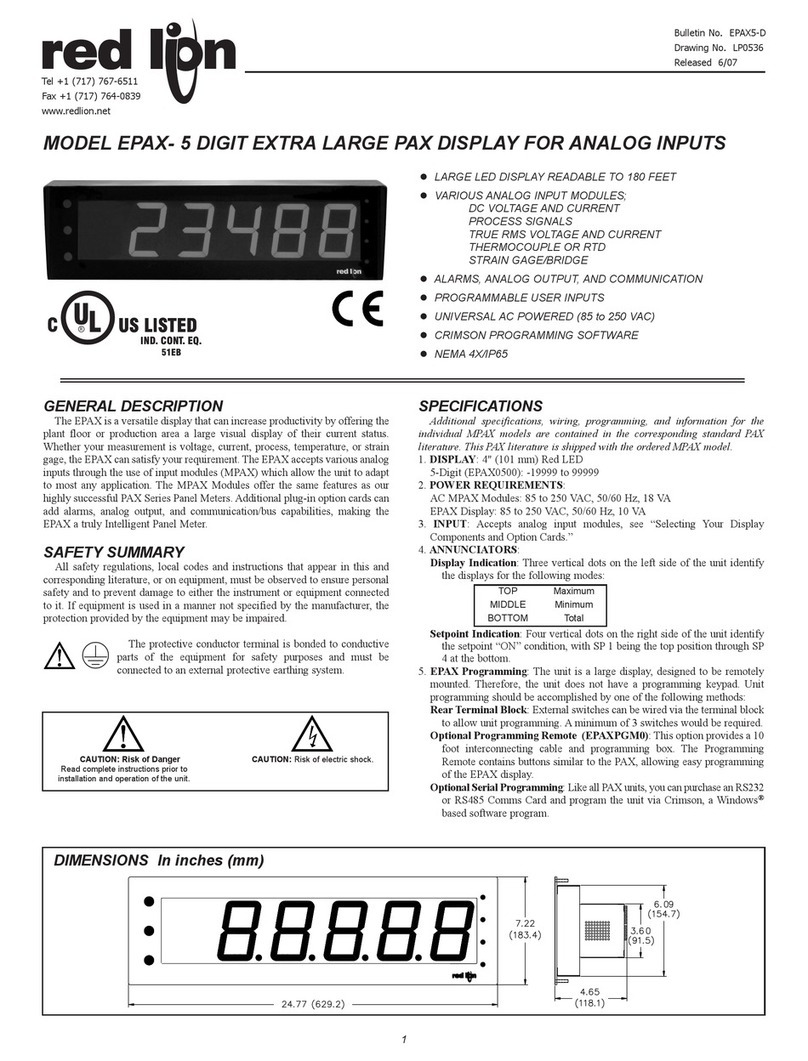
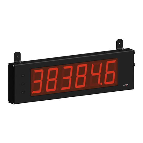
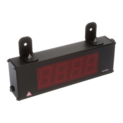
red lion LPAXDA User manual

1
GLARGE LED DISPLAY READABLE TO 70 FEET
GDUAL PROCESS SIGNAL INPUT MODULE
GALARMS, ANALOG OUTPUT, AND COMMUNICATION
GCUSTOM UNITS LABEL WITH BACKLIGHT
GPROGRAMMABLE USER INPUTS
GPROGRAMMABLE FUNCTION KEYS
GUNIVERSAL AC/DC POWERED MODELS
GCRIMSON SOFTWARE FOR METER CONFIGURATION
GNEMA 4/IP65
GENERAL DESCRIPTION
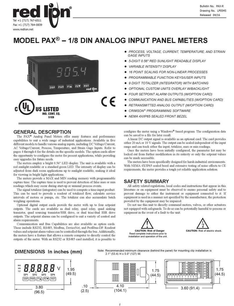
The LPAXDA Display is a versatile display that can increase productivity by
offering the plant floor or production area a large visual display of their current
status. With the use of a units label and backlighting, the display can be tailored
to show the actual engineering unit, which further enhances the display. This
LPAXDA display accepts various analog inputs through the use of input
odules (MPAXDP) which allow the unit to adapt to ost any application. The
MPAXDP Modules offer the sa e features as our highly successful PAXDP
Series Panel Meters. Additional plug-in option cards can add alar s, analog
output, and co unication/bus capabilities, aking the LPAXDA a truly
Intelligent Panel Meter.
SAFETY SUMMARY
All safety regulations, local codes and instructions that appear in this and
corresponding literature, or on equip ent, ust be observed to ensure personal
safety and to prevent da age to either the instru ent or equip ent connected
to it. If equip ent is used in a anner not specified by the anufacturer, the
protection provided by the equip ent ay be i paired.
The protective conductor ter inal is bonded to conductive
parts of the equip ent for safety purposes and ust be
connected to an external protective earthing syste .
SPECIFICATIONS
Additional specifications, wiring, programming, and information for the
individual MPAX models are contained in the corresponding standard PAX
literature. This PAX literature is shipped with the ordered MPAX model.
1. DISPLAY: 1.5" (38 ) Red LED
5-Digit: (-19999 to 99999)
2. POWER REQUIREMENTS:
AC Modules: 85 to 250 VAC, 50/60 Hz, 21 VA
DC Modules: 18 to 36 VDC, 13 W or 24 VAC ±10%, 50/60 Hz, 16 VA
3. INPUT: Accepts analog input odules, see “Selecting your display
co ponents.”
4. ANNUNCIATORS:
LPAXDA00: A, B, C, SP1, SP2, SP3, and SP4
Optional units label with backlight
5. KEYPAD: Five tactile e brane switches integrated into the front panel
6. CERTIFICATIONS AND COMPLIANCES:
UL Recognized Co ponent, File #E179259, UL3101-1, CSA 22.2 No. 1010-1
Recognized to US and Canadian require ents under the Co ponent
Recognition Progra of Underwriters Laboratories, Inc.
UL Listed, File # E137808, UL508, CSA C22.2 No. 14-M95
LISTED by Und. Lab. Inc. to U.S. and Canadian safety standards
Type 4 Enclosure rating (Face only), UL50
IECEE CB Sche e Test Certificate #UL/8843/UL
CB Sche e Test Report #04ME11209-20041018
Issued by Underwriters Laboratories, Inc.
IEC 1010-1, EN 61010-1: Safety require ents for electrical equip ent for
easure ent, control, and laboratory use, Part 1.
IP65 Enclosure rating (Face only), IEC 529
ELECTROMAGNETIC COMPATIBILITY
EMC specifications deter ined by the MPAX odule.
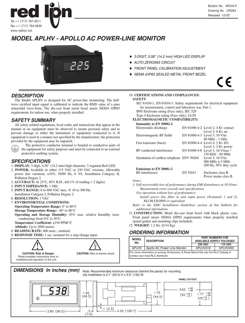
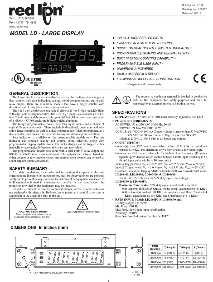
MODEL LPAXDA- 5 DIGIT LARGE PAX DISPLAY FOR DUAL ANALOG INPUTS
DIMENSIONS In inches (mm)
CAUTION: Read complete
instructions prior to installation
and operation of the unit.
CAUTION: Risk of electric shock.
PANEL CUT OUT
Bulletin No. LPAXDA-X
Drawing No. LP0602
Effective 1/05
el +1 (717) 767-6511
Fax +1 (717) 764-0839
www.redlion.net
CUS LISTED
UL
R
IND. CONT. EQ.
51EB

WARNING: Disconnect all power to the unit before
installing Plug in cards.
Adding Option Cards
The MPAX series eters can be fitted with up to three optional plug-in cards.
However, only one card fro each function type can be installed at a ti e. The
function types include Setpoint Alar s (PAXCDS), Co unications
(PAXCDC), and Analog Output (PAXCDL). The cards can be installed initially
or at a later date. Each optional plug-in card is shipped with installation and
progra ing instructions.
COMMUNICATION CARDS (PAXCDC)
A variety of co unication protocols are available for the PAX and MPAX
series. Only one of these cards can be installed at a ti e. When progra ing
the unit via Cri son, a Windows®based progra , the RS232 or RS485 Cards
ust be used.
*Units available in various connector configurations.
SETPOINT CARDS (PAXCDS)
The MPAX series has four setpoint alar output plug-in cards. Only one of
these cards can be installed at a ti e. (Logic state of the outputs can be reversed
in the progra ing.) These plug-in cards include:
PAXCDS10 - Dual Relay, FORM-C, Nor ally open & closed
PAXCDS20 - Quad Relay, FORM-A, Nor ally open only
PAXCDS30 - Isolated quad sinking NPN open collector
PAXCDS40 - Isolated quad sourcing PNP open collector
LINEAR DC OUTPUT (PAXCDL)
Either a 0(4)-20 A or 0-10 V retrans itted linear DC output is available
fro the analog output plug-in card. The progra able output low and high
scaling can be based on the input, ax, in, or total display value. Reverse
slope output is possible by reversing the scaling point positions.
PAXCDL10 - Retrans itted Analog Output Card
UNITS LABEL (LX)
The LPAX Display has an area on the front panel designed for a custo units
label. The units label is applied directly to the panel in the e bossed area. The
units backlight is then turned on via progra ing.
Refer to the LPAX Accessories Bulletin for a list of available units labels.
PROGRAMMING SOFTWARE
Cri son 2 (SFCRD2) is a Windows®based progra for configuring and
updating the fir ware of the MPAXDP eter fro a PC. Using Cri son 2
akes progra ing the MPAXDP eter easier and allows the user to save the
MPAXDP database in a PC file for future use. Cri son is available as a free
download fro Red Lion’s website, or it can be purchased on CD.
The first ti e Cri son 2 is run fro the File enu, select “New” to display
a dialog and select the MPAXDP. The screen will display icons that represent
the various progra ing sections of the MPAXDP. Double-click on an icon to
configure the progra ing para eters pertaining to the selection. Tool Tip help
is available for each of the progra para eters. A PAX serial plug-in card is
required to progra the eter using the software.
MPAX MODULES *
SIGNAL TYPE INPUT RANGES
85 250 VAC 11 to 36 VDC/ 24 VAC
LPAX DISPLAY
Dual Process Inputs 0-20 mA or 0-10 VDC MPAXDP00 MPAXDP10 LPAXDA00
7. ENVIRONMENTAL CONDITIONS:
Operating Te perature Range: Deter ined by the MPAX odule
Storage Te perature Range: -40 to 60°C
Operating and Storage Hu idity: 0 to 85% ax. RH (non-condensing)
Altitude: Up to 2000 eters
8. MOUNTING REQUIREMENTS:
Max. panel thickness is 0.375" (9.5 )
Min. panel thickness for NEMA 4/IP65 sealing is 0.060" (1.57 )
9. MODULE INSTALLATION:
24-pin shrouded connector on LPAX engages connector on MPAX odule
upon installation. Shroud ensures proper align ent by providing a lead-in for
the odule connector.
10. CONNECTIONS: All wiring connections are ade to the MPAX odule
via high co pression cage-cla p ter inal blocks. Wiring instructions are
provided with the MPAX odule.
CAUTION: DISCONNECT ALL POWER BEFORE
INSTALLING OR REMOVING MODULE
11. CONSTRUCTION: Steel front panel, enclosure, and rear cover with
textured black polyurethane paint for scratch and corrosion resistance
protection. Sealed front panel eets NEMA 4/IP65 specifications for indoor
use when properly installed. Installation Category II, Pollution Degree 2.
Panel gasket and keps nuts included.
12. WEIGHT: 2.7 lbs (1.2 kg) (less module)
*For detailed Module specifications, see corresponding PAX literature. (i.e. For MPAXDP specifications, see the PAXDP literature)
OPTIONAL PLUG-IN CARDS AND ACCESSORIES
Ab ut the MPAX Input M dules
The MPAX Module serves as the input to the LPAX Display. The MPAX odule provides input scaling which allows the LPAX to display ost any engineering
unit. Once the MPAX is inserted into the LPAX, the unit has the sa e functions and capabilities of our PAX Series Intelligent Panel Meters. A full set of PAX
progra ing instructions will be included with the MPAX Module.
Note: The MPAX provides the operating power for the LPAX, therefore you must select either the A or D MPAX corresponding with your application and available
power.
Selecting Y ur Display C mp nents
To build a co plete display unit, you will need an LPAXDP and an MPAXDP Input Module. The LPAX is only a display and will not operate without an MPAX
Module. Please use the following chart to identify the appropriate MPAX Module (including supply power) and LPAX Display that will satisfy your application.
PAXCDC30 - DeviceNet
PAXCDC50 - Profibus-DPPAXCDC2* - RS232 Serial
PAXCDC4* - ModbusPAXCDC1* - RS485 Serial
CAUTION: The MPAX main circuit board and the option cards
contain static sensitive components. Before handling the module
or the cards, discharge static charges from your body by
touching a grounded bare metal object. Handle the module by
the rear plastic cover only, and the option cards by the board
edges. Dirt, oil or other contaminants that contact the circuit
boards or components can adversely affect circuit operation.
WARNING: Exposed line voltage exists on the MPAX main circuit
board and the option cards. DO NOT apply power to the
module OR load circuits until the module is properly installed
in the LPAX case.
NOTE: All module and option card labels must be installed as
shown for safety purposes.
3
Rem ving The MPAX M dule
To re ove the MPAX Module fro the LPAX Display, first
re ove all power and load circuits. Then insert a flat
screwdriver blade (3/16" or 1/4") into the narrow slot
between the LPAX rear cover plate and the
odule’s plastic cover as illustrated in Figure
2. Twist the screwdriver in the direction
shown to disengage the internal
connectors while fir ly
squeezing and pulling back
on the rear finger tabs
(top and botto ).
Carefully slide the
odule out of the
LPAX case, keeping it
properly aligned with
the case opening.
1.0 ASSEMBLING THE DISPLAY
Prior to installing the LPAX Display, it is reco ended that the MPAX
and any option cards be asse bled first. This will allow you the
opportunity to insure all the boards are fitted properly into their
connectors.
Installing the Opti n Cards
If your application requires option
cards, they should be installed into the
MPAX before it is installed into the
LPAX Display. Refer to the
literature enclosed with the option
cards for installation instruction.
Installing the MPAX
To install the MPAX Module,
align the odule with the opening
in the LPAX case, as illustrated.
The odule ust be oriented as
shown, with ter inal #1 toward the
top of the LPAX case. Carefully
slide the odule into the LPAX case.
The LPAX and MPAX connectors will begin
to engage about ¼" fro the botto . At this point,
apply a s all a ount of pressure to the rear of the
MPAX odule to fully engage the connection. Be sure the
odule fully snaps into the slots at the rear of the LPAX case. The
display is ready for installation.
Installing the Labels
Each option card and the MPAX are shipped with a connection label. These
labels ust be applied to the rear of the LPAX in the positions shown in the
drawing.
Figure 1, Installing an MPAX Module and Option Cards
Figure 2, Removing an MPAX Module

Once asse bled, the LPAX and MPAX have all the sa e functions and
capabilities of our PAX Series Intelligent Panel Meters. Therefore, you will find
the appropriate PAX infor ation packed with the MPAX Module. Si ply
follow the instructions to wire and progra the display for your application.
TROUBLESHOOTING
For technical assistance, contact technical support.
2.0 INSTALLING THE DISPLAY
3.0 WIRING AND PROGRAMMING THE DISPLAY
LPAX DISPLAY INSTALLATION
The LPAX display is intended to be ounted into a panel or
enclosure. The display is provided with a gasket to provide a
water-tight seal. The reco ended ini u panel thickness
for NEMA 4/IP65 sealing is 0.060" (1.57 ).
For panel ounting, prepare the panel cut-out to the
di ensions shown. The supplied te plate ay be used to
ark the cut-out and hole locations on the panel. After
the panel cut-out has been deburred, slide the panel
gasket over the rear of the display and onto the
ounting studs. Insert the display into the panel
cut-out as illustrated in Figure 3. Install six # 10-32
keps nuts (supplied) and tighten evenly for unifor
gasket co pression. Do not over-tighten the nuts.
By using additional ounting accessories, the
LPAX can be surface-wall ounted, suspended, or
botto ounted. Separate installation instructions
are provided with the ounting accessories.
Envir nment And Cleaning
The display should be installed in a location that
does not exceed the axi u operating te perature
and provides good air circulation. Placing the syste
near devices that generate excessive heat should be
avoided.
The bezel should be cleaned only with a soft cloth
and neutral soap product. Do NOT use solvents.
Continuous exposure to direct sunlight ay accelerate
the aging process of the bezel.
Figure 3, Installing The LPAX Into A Panel
ORDERING INFORMATION
* See the LPAX Accessory Bullet n or our web s te for ava lable un ts labels.
MODEL NO. DESCRIPTION PART NUMBERS
LPAXDA 5-D g t, Large D splay for Analog MPAXDP Modules LPAXDA00
Optional
Plug In
Cards
PAXCDC
PAXCDS
Extended RS485 Ser al Commun cat ons Output Card w th Dual RJ11 Connector
Dual Setpo nt Relay Output Card
PAXCDC1C
PAXCDS10
TYPE
RS232 Ser al Commun cat ons Output Card w th Term nal Block
Quad Setpo nt Relay Output Card
PAXCDC20
PAXCDS20
MPAXDP
Display
Extended Modbus Commun cat ons Card w th Dual RJ11 Connector
Extended RS232 Ser al Commun cat ons Output Card w th 9 P n D Connector
Quad Setpo nt S nk ng Open Collector Output Card
PAXCDC4C
PAXCDC2C
PAXCDS30
ENC9 NEMA 4 Enclosure for LPAX
Prof bus-DP Commun cat ons Card
Dev ceNet Commun cat ons Card
Quad Setpo nt Sourc ng Open Collector Output Card
PAXCDC50
PAXCDC30
PAXCDS40
ENC90000
MB
SHR Shroud for LPAX
PAXCDL Analog Output Card
Modbus Commun cat ons Card
RS485 Ser al Commun cat ons Output Card w th Term nal Block
PAXCDL10
PAXCDC40
PAXCDC10
SHRLPAX0
Analog
Input Module
Mount ng Bracket for LPAX
LX Custom Un ts Label * L sted Separately
MBLPAX00
Accessories
SFCRD2 PC Conf gurat on Software for W ndows 98, ME, 2000, XP SFCRD200
Dual Process Input Module, AC Powered MPAXDP00
Dual Process Input Module, DC/24 VAC Powered MPAXDP10
Table of contents
Other red lion Monitor manuals

red lion
red lion LPAX Series User manual

red lion
red lion PGMMODC1 User manual

red lion
red lion LD200400 User manual

red lion
red lion BFD User manual

red lion
red lion IMA User manual

red lion
red lion GTM User manual

red lion
red lion LD User manual

red lion
red lion LD Series User manual

red lion
red lion PAX User manual

red lion
red lion LPAX User manual