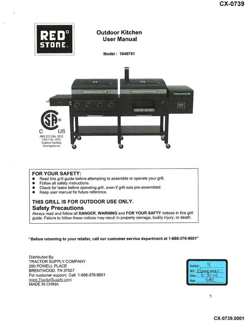
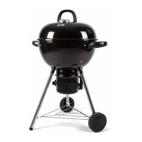
Red Stone 1046761 User manual

5TO
ll
E
REBO
Outdoor
Kitchen
User
Manual
Model
1046761
Al’lS
Z3?
l?tr
t’i
S?
1.?
tr
?12
?udcor
f?c
king
?
?ppl?atrce
FOR YOUR
SAFETY
o
Read
this
grill
guide
before attempting to
assemble
or
operate your
grill
o
Follow
all
safety
instructions
o
Check
for
leaks before operating
grill
even
if
grill
was
pre
assembled
o
Keep
user
manual
for
future
reference
THIS GRILL
IS
FOR OUTDOOR USE
ONLY
Safety Precautions
Always
read
and
follow
all
DANGER WARNING
and
FOR YOUR
SAFTY
notices
in this
grill
guide
Failure
to follow
these
notices
may
result
in
property
damage
bodily
injury
or
death
Before
returning to
your
retailer call
our
customer
service department
at
1
888 376 9601
Distributed
By
TRACTOR
SUPPLY
COMPANY
2OO POWELL
PLACE
BRENTWOOD TN
37027
For
customer
support
Call
1
888376
9601
rurywJrccter lBplv
?alo
MADE
IN
CHINA
1
All manuals and user guides at all-guides.com
all-guides.com

TABLE OF
CONTENTS
SAFETY
INFORMATION
PARTS
LIST
HARDWARE
LIST
EXPLODED VIEW
TOOLS
LIST
ASSEMBLY
INSTRUCTIONS
GAS
GRILL
OPERATION
INSTRUCTIONS
GAS
GRILL
CARE
AND
MAINTENANCE
CHARCOAL
GRILL
OPERATION
INSTRUCTIONS
CHARCOAL
GRILL
CARE
AND
MAINTENANCE
REPLACEMENT
PARTS
LIST
23
27
30
32
33
3
5
7
7
7
8
AwnRnrruc
1
Do
not store or
use
gasoline or other
flammable
vapor
and
liquids
in
the
vicinity
of
this
or
any
other
appliance
2
A
LP
cylinder not
connected
for
use
should not
be
stored
in
the
vicinity
of
this
or
any
other
appliance
AoRruCeR
lf
you
smell
gas
1
Shut
off
gas
to
the appliance
2
Extinguish
any
open
flame
3
Open
lid
4
lf
odor
continues
keep
away
from
appliance
and
call
your
local
fire
department
2
All manuals and user guides at all-guides.com

A
slrew
nroRuRnoru
1
Grill
installation
must conform
with
local
codes
or
in
the
absence
of
local
codes
with
the
National
Fuel
Gas
Code
ANSI
2223.1
NFPA
54
Natural
Gas
and Propane
lnstallation
Code
CSA
8149.1
or
Propane
Storage
and
Handling
Code
8149.2
or the
Standard
for
Recreational Vehicles
ANSI
A
I
19.2
NFPA
1192 and
CSA2240
RV
Series Recreational Vehicle
Code
as
applicable
2
This
gas
grill
is
intended
for
outdoor
use
only
and
should
not
be used
in
a
building
garage
or
any
other
enclosed
area
3
Never
attempt
to attach
this
grill
to
the
self
contained
propane
system
of
a
boat
camper
trailer
motor
home
or
house
4
Never use any
other
type
of
fuel
for this
grill
other
than
LP
gas
propane
5
Only
use
the pressure
regulator with
the type
1
connector
that
is
supplied with
this
gas
grill
6
Do
not
stoie
or
use
gasoline or
any
other
flammable vapors
and
liquids
within
300
in
8m
of
this
or
any
other
appliance
7
An
LP
cylinder not
connected
for
use
should
be
stored
a
minimum
of
120
in
3m
away
from
this
or
any
other
appliance
8
Only
a
20
lb
LP
gas
cylinder
is
allowed
The
cylinder
must
be
constructed
and marked
in
accordance
with
the
Specifications
for
LP Gas
Cylinders
of
the
U
S
Department
of
Transportation
DO
T
or
the
National
Standard
of
Canada
CAN
CSA
8339
Cylinders
Spheres
and Tubes
for
Transportation
of
Dangerous
Goods
and
Commission
A
20
lb
LP
Gas
cylinder’s
dimensions
are
9
This
grill
is for
use
with
propane gas
only
propane
gas
cylinder not
included
10
Do
not
attempt
to
move
the
grill
while
it
is
lit
or
when
it
is
hot
The
castors
should
be
locked
when
not
moving
the
grill
11
Do
not
use
the
grill
unless
it
is
completely
assembled
and
all
parts
are
securely
fastened
and
tightened
12
Keep
all
combustible
items
and
surfaces at
least
36
in
91
44cm
away
from
the
grill
at
all
times
13
Do
not
use
in
an
explosive
atmosphere
14
Keep
grill
area
clear
and
free
from combustible
materials
gasoline
and
other
flammable vapors
and
liquids
15
Do
not obstruct the flow of
combustion
and
ventilation
air
16
Keep
the
ventilation
opening
s
of the cylinder
enclosure
free
and
clear
from
debris
17
Visually
check
burner flames
including
pilot
burner
flame
if
provided
with
pictorial
representations
18
Do
not
touch
metal
parts of
grill
until
it
has
completely cooled
about
45
minutes
to
avoid
burns
unless
you
are wearing
protective
gear pot holders glovers
BBQ
mittens
etc
19
Do
not
alter this
grill
in
any manner
20
Clean
and
inspect
the
hose
before
each use
lf
there
is
evidence
of
abrasion
wear
cuts
or
leaks
the
hose
must
be
replaced
prior
to
operating the appliance
The
replacement
hose assembly
will
be
that
which
is
specified
by
Tractor
Supply
Company
listed in
the
repair
parts
list
in this
manual
21
Move
gas hoses as
far
away
as
possible
from
hot surfaces
and
dripping hot
grease
22
Always
perform
a
leak
test
before
operating
grill
23
Keep
the
grill’s
valve
compartment
burners
and
circulating
air
passages
clean
lnspect the
grill
before
each
use
Do
not obstruct the flow of
gas
or
ventilation
air
24
lrhe
use
of
alcohol
prescription or
non
prescription
drugs
may
impair
the
operator’s
ability
to
properly
assemble
or safely
operate
the
grill
25
Always
open
grill
lid
slowly
and
carefully
as
heat
and
steam
trapped
within
the
grill
can
burn
you
severely
26
Do
not leave
a
lit
grill
unattended
Keep
children
and
pets
away
from
the
grill
at
all
times
27
Do
not
place
this
grill
on
any
type of tabletop
surface
The
grill
should
be
placed
on
a
flat
and
level
surface
28
Do
not
use
the
grill
in
high
winds
18
in
12.2in
tn
12.3
in
3
I
All manuals and user guides at all-guides.com

ACAUTION
o
Never
use
charcoal
or
lighter fluid
with
the
grill
o
Do
not
use
gasoline
kerosene
or alcoholfor
lighting
o
The LP
gas
cylinder
used
with
this
appliance
must
be
a
Constructed
and marked
in
accordance
with
the
Specifications
for
LP
Gas
Cylinders
of
the
U
S
Department
of
Transportation
DO
T
or
the
National
Standard
of
Canada
CAN
CSA
8339
Cylinders
Spheres
and Tubes
for
Transportation of
Dangerous
Goods
and
Commision
as
applicable
and
b
Provided
with
a
listed overfilling
prevention
device
c
Provided
with
a
cylinder
connection device compatible
with
the connector
for
outdoor
cooking
appliances This
grill
is
not
intended
to
be used
in
or
installed
on
recreational vehicles
and
or
boats
a
Never
keep a
filled
container
in
a
hot
car
or
car
trunk
Heat
will
cause
the
gas
pressure
to
increase
which
may
open
the
relief
valve
and
allow
gas
to
escape
o
Always
open
grill
lid
slowly
and
carefully
as
heat
and
steam
trapped
within
the
grill
can
burn
you
severely
?
SAFETY INFORMATION
AwRRtrutr
c
1
Do
not store
a
spare
LP
Gas
cylinder
under
or
near the
grill
2
Never
fill
the cylinder
beyond
80
percent
full
and
3
lf
the
information
in
1
and
2
is
not
followed
exactly
a
fire
causing
death
or
serious
injury
may
occur
Place
dust
cap on
cylinder
valve
outlet
whenever
the
cylinder
is
not
in
use
Only
install
the type of
dust
cap
on
the
cylinder
valve
outlet
that
is
provided
with
the
cylinder
valve Other types
of
caps
or plugs
may
result
in
leakage
of
propane
A
wRRt
ltlc
o
Do
not place the
grill
under
overhead
combustible
construction
or
awnings
Minimum
clearance
from
sides
and back
of
unit
to
combustible
construction
is
36
inches
914.4mm
NOTE
The
installation
must conform
with
local
codes
or
in
the
absence
of
local
codes
ANSI2223.1
NFPA
54
Natural
Gas
and Propane
lnstallation
Gode CSA
8149.1
or
Propane
Storage
and
Handling
Code
8149.2
4
All manuals and user guides at all-guides.com

PARTS
LIST
o
17
Gas
Side Burner
Knob
1 pc
19
18
Gas
Side Burner
Drip
Pan
2
pcs
Bezel
1pc
20
Drip
Pan
Handle
3
pcs
13
SwivelCastor
withoutlock
4pcs
14
Bottle
Opener
1pc
16
Side Burner
15
Towel
Rail
I
Assembly
1pc
pc
10
Back
Right
Leg
1
pc
9
Front
Right
Leg
1
pc
12
Swivel
Locking
Castors
2
pcs
I
L
Charcoal
Bottom
Panel
1pc
5
Bottom
Panel
1pc
8
Charcoal
Lid
and
Firebox
Assembly
1
pc
7
Decoration
trim
3
6
Weight 2pcs
pcs
2
Left
Leg
Assembly
1pc
1
Gas
Lid
and
Firebox
Assembly
1pc
4
Back
Middle
Leg
1
pc
3
Front
Middle
Leg
1
pc
5
All manuals and user guides at all-guides.com

41
Cooking
Grate
5
42
Warming
Rack
2
pcs
43
Gas Tank
Bracket
1pc
44
Grate Tool
I
pc
37
Smoker
Lid
Assembly
1pc
38
Hinge
Pin
2
pcs
39
Smoker
Side
Door
Assembly
1pc
40
Smoker
Charcoal
Grate
1pc
33
Accessories
1Pc
34
Stack
1pc
35
Smoker
Connection
Panel
1pc
36
Smoker
Firebox
1
29
Handle
Base
1Pc
30
Charcoal
Pan
Support
2
pcs
31
Charcoal
Pan
I
Pc
32
Charcoal
Pan
Handle
1pc
25
Right
Lifting
Stator
1
26
Cantilever
Arm
Pin
6
pcs
27
Coller
Pin
10
pcs
28
Drive Shaft
Assem 1
?
6?
21
Upper
Left
CantileverArm
1pc
22
Upper
Right
Cantilever
Arm
1
23
Lower
Cantilever
Arm
2
24
Left
Lifting
Stator
1
6
All manuals and user guides at all-guides.com
all-guides.com

45
Flame
Tamer
4
pcs
46
Match
Holder
1pc
HARDWARE
LIST
a
M6x12
bolts
68
pcs
EXPLODED
VIEW
44 42 19
20 34
13 21
33
29
2
31
t?
3r
3?
11
r
2
22
7
G
41
43
4?
4S
f
8
J
3
32
3
TOOLS
LIST
7
a
G
q
3
17
mm
Wrench
I
pc
Phillips
Head
Screwdriver
1
Tools
for
assem
included
All manuals and user guides at all-guides.com

ASSEMBLY
INSTRUCTIONS
Before
assembly
read
instructions
carefully
Assemble
grill
on
a
clean
flat
surface
This
unit
is
heavy
DO NOT
ASSEMBLE
WITHOUT
ASSISTANCE
GET
A HELPER
Step
I
Unscrew
2
pre
assembled
bolts
from the
gas
lid
and
firebox
assembly
1
as
shown
in
image
I
Attach
left
leg
assembly
2
to
gas
lid
and
firebox
assembly
1
using
4
M6x12
bolts
a
as
shown
in
image
2
lmage
1
lmage
2
R
s
t
0
2
d
Bolts
M6x
12
bolts
Step
2
Unscrew 2
pre
assembled
bolts
from
gas
lid
and
firebox
assembly
1
as
shown
in
image
3
Attach
front
middle
leg
3
and back
middle
leg
4
to
gas
lid
and
firebox
assembly
1
using
4
M6x12
bolts
a
as
shown
in
image
4
lmage
3
lmage
4
t
?
?
a
o
o
m
?
1
h
3
a
4
8
?
dB
u
B
NB
c
u??
UB
Bolts
M6x
12
bolts
Q
All manuals and user guides at all-guides.com

Step
3
Unscrew
the
pre
assembled
bolts
nuts
and
washers
from
weight
6
as
shown
in
image
5
then
attach
the weight
6
to
bottom panel
5
as
shown
in
image
6
Attach the bottom panel
to legs using
4 M6x12
bolts
a
as
shown
in
image
6
lmage
6
lmage
5
ASSEMBLY
INSTRUCTIONS
Bolts
Nuts
Washers
M6x
12
bolts
Step
4
Attach
2pcs
decoration
trims
7
to
Legs
using
4
M6x12
bolts
a
as
shown
in
image
7
lmage
7
s
s
t
5
6
M6
x
12
bolts
7
?
9
l
e
?
r
l
t
f
iJ
?
c
3
7
0
All manuals and user guides at all-guides.com

ASSEMBLY
INSTRUCTIONS
Step
5
Unscrew 2
pre
assembled
bolts
from charcoal
lid
and
firebox
assembly
B
as
shown
in
image
8
attach
charcoal
lid
and
firebox
assembly
8
to
legs
using
4
M6x12
bolts
a
as
shown
in
image
9
lmage
3
lmage
9
o
8
Bolts
M6X
12
bolts
Step
6
Unscrew 2
pre
assembled
bolts
from charcoal
lid
and
firebox
assembly
8
as
shown
in
image
10
and
attach
front
right
leg
9
and back
right
leg
10
to
charcoal
lid
and
firebox
assembly
8
using
4 M6x12
bolts
a
as
shown
in
image
11
lmagel
0
lmagel
l
10
I
?
Bolts
M6x
12
bolts
0
0
0
o
0
I
10
All manuals and user guides at all-guides.com

ASSEMBLY
INSTRUCTIONS
Step
7
Unscrew
the
pre
assembled
bolts
nuts
and
washers
from weight
6
as
shown
in
image
12
then
attach
the weight
6j
to
charcoal bottom
panel
11
as
shown
in
image
12
altach
the charcoal bottom panel
1
1
to
Legs
using
4
M6x12
bolts
a
as
shown
in
image
13
lmagel2
Bolts
Nuts
Washers
lmagel3
11
M6
2
bolts
Step
I
Attach decoration
trim
7
to legs using
2
M6x12
bolts
a
as
shown
in
image
14
lmagel4
6
0
7
t
I
1
ge
O
?
I
M6
X
12
bolts
0
11
All manuals and user guides at all-guides.com
all-guides.com

ASSEMBLY
INSTRUCTIONS
Step
9
Attach
2
swivel
locking
castors
12
and4
swivelcastors
without
lock
13
to legs
as
shown
in
image
15
lmagel
S
12
13
Step
10
Unscrew
the
pre
assembled
bolts
from
left
leg
assembly
2
as
shown
in
image
16
then
attach
bottle
opener
14
and
the
match
holder
46
to
left
leg
assembly
2
using
unscrewed
bolts
lmagel6
?
Q
?
Q
N
2
l2
All manuals and user guides at all-guides.com

ASSEMBLY
INSTRUCTIONS
Step
1l
Unscrew
the
pre
assembled
bolts
from
towel
rail
15
as
shown
in
image
17
then
attach
towel
rail
15
to
side
burner
assembly
16
using
unscrewed
bolts
lmagel
T
Bolts
16
15
Step
12
Unscrew
the
pre
assembled
bolts
from
side
burner
assembly
16
as
shown
in
image
18
and
take out
the
side
burner Attach
side burner
assembly
16
to legs
using
4lt
6x12
bolts
a
as
shown
in
image
19
lmagel
S
16
Side
burner
lmagel9
Bolts
o
o?
o
0
a
c
a
tr
M6X
12
bolts
13
All manuals and user guides at all-guides.com

ASSEMBLY NSTRUGTIONS
Step
13
Unscrew
the
pre
assembled
bolts
from
side burner
valve
as
shown
in
image
20
then
attach side
burner
valve
and
ga?
side
burner
bezel
18
to
side
burner
assembly
16
using
unscrewed
bolts
as
shown
in
mage
21
Re
attach side burner
?o
side
burner
assembly
16
using
unscrewed
bolts
as
shown
in
image
22
insert
ignition
wire
into ignition
pin
Attach
gas
side
burner
knob
17
to side
burner
assembly
16
lmage20
Side
burner
valve
Bolts
lmage2l
18
16
Bolts
lmage22
17
Side
burner
valve
lgnition
pin
lgnition
wire
Side
burner
?
?
?
16
o
?
?
BoIts
T4
All manuals and user guides at all-guides.com

ASSEMBLY
INSTRUCTIONS
Step
14
Unscrew
the
pre
assembled
bolts
from
drip
pan
handle
20
aq
shown
in
image
23
and
attach
drip
pan
handle
20
t?
drip
pan
19
using
unscrewed
bolts
Put
two
drip
pan
assemblies
into
the
fire
box
of
gas
grill
and
charcoal
grill
respectively
lmage
23
19
20
Bolts Drip
pan
assemblies
Step
15
Attach
upper
left
cantilever
arm
21
lower
cantilever
arm
23
left lifting
stator
24
and
charcoal
pan
support
iO
togetl?er using
3
caniilever
arm
pins
26
and
3
c
otter
pins
27
as
show
n
in
image
24
Atiach
u?p?r
ri?rrt
cantilev?r
arm
22
lower
cantilever
arm
23
right
lifting
stator
25
and
charcoal
pan
support iO to?
tt
r
using
3
cant?lever
arm
pins
26
and
3
cotter pins
27
as
shown
in
image
25
lmage
24
lmage
25
21
23
22
30
26
25
24 23
27
27
c
?
?
a
o
o
o
Left
cantilever
arm
assemblY
Left
cantilever
arm assemblY
15
All manuals and user guides at all-guides.com

ASSEMBLY
INSTRUCTIONS
Step
16
Attach the
drive shaft
assembly
28
through the
left
and
right
cantilever
arm
assemblies then
insert
the
cotter pins
27
lo
the
holes of drive shaft
assembly
28
as
shown
in
image
26
Attach the
finished
assembly
and
handle
base
29
to
charcoal
firebox
using
4
M6x12
bolt
a
as
shown
inimage2T
lmage
26 27
28
Left
cantilever
arm assembly
lmage2T
Right cantilever
arm assembly
29
M6X
12
bolts
a
r
Step
17
Attach charcoal
pan
31
to
charcoal
firebox
using
4 M6x12
bolts
a
as
shown
in
image
28
Attach the
charcoal
pan
handle
32
to
charcoal
firebox
lmage
28
31
Bolt
32
t
a
?
?
q
???
ss
?s
?c
?
?s
s
ss?
?
?
?o
?s
?
?c
??
G?
??
0
3
M6X 1
bolts
Bolt I6
All manuals and user guides at all-guides.com
all-guides.com

ASSEMBLY
INSTRUCTIONS
Step
18
Att?ch Accessories
33
to
charcoal
firebox
using
4
M6x12
bolts
a
as
shown
in
image
29
lmage
29
33
step
19
M6x
12
bolts
Unscrew
the
4
pre
assemble
bolts
from the top
of
the stack
34
to
take
off
the
stack
cover
as
shown
in
image
30
Unscrew
the
pre
assembled
bolt
to
take
off
the
butterfly
damper
as
shown
in
shown
in
image
30
Attach the stack
to
the
charcoal
lid
using
2
lt
6x12
bolts
a
as
shown
in
image
31
Attach the
butterfly
damper
to
the stack using
unscrewed
bolt
Attach
the
stack
cover
to
the
Stack
using
4
unscrewed
bolts
lmage
30
Bolt
Stack
cover
Butterfly
damper
34
Its
Bo
Butterfly
damper
lmage
31
Stack
M6
x
12
bolts
Charcoal
lid
a
rc
cover
I
g6
t7
All manuals and user guides at all-guides.com

ASSEMBLY
INSTRUCTIONS
Step
20
Attach the
smoker
connection
Panel
35
to
the
right
side
panel
of
charcoal
firebox
using
4
M6x12
bolts
a
as
shown
in
image
32
lmage
32
35
T
I?
J
IJ
M6x
12
bolts
?
?
Step
2l
Attach
smoker
firebox
assembly
36
to
legs
using
4
M6x12
bolts
a
as
shown
in
image
33
Attach the
smoker
connection
panel
35
t?
the
smok?r
firebox
assembly
36
using
B
M6x12
bolts
a
lmage
33
35 36
6
?
?
l
?
?
M6X
2
bolts
M6X
12
bolts
18
All manuals and user guides at all-guides.com

ASSEMBLY
INSTRUCTIONS
Step
22
Unscrew
the
pre
assembled
bolts
from
drip
pan
handle
20
as
shown
in
image
34
and
attach
the
drip
pan
handle
20
to
smoker
lid
assembly
37
using
unscrewed
bolts
lmage
34
3T
20
Bolts
Step
23
Attach the
smoker
lid
assembly
to
smoker
firebox
assembly
using
2
hinge
pins
38
and 2
cotter pins
27
as
shown
in
image
35
lmage
35
Smoker
lid
assembly
27
t
REW
E?rcha
o
?
I
o
o
38
l9
All manuals and user guides at all-guides.com

ASSEMBLY
INSTRUCTIONS
Step
24
Attach
the
smoker
side
door
assembly
39
to
the
right
side
panel
of
smoker
firebox
assembly
36
using
2M6x12
bolts
a
as
shown
in
image
36
lmage
36
M6x
12
bolts
Step
25
Put the
smoker
charcoal
grate
40
into
the
smoker
firebox
as
shown
in
image
37
lmage
37
40
39
t
N
20
All manuals and user guides at all-guides.com
Other manuals for 1046761
1
Table of contents
Other Red Stone Grill manuals
Popular Grill manuals by other brands
Napoleon
Napoleon PRESTIGE V 450 instruction manual

Coleman
Coleman 9992-644 Use, care & assembly manual

KitchenAid
KitchenAid 720-0891CD Installation Instructions and Use & Care Guide

Z GRILLS
Z GRILLS ZPG - 50B owner's manual

T-Fal
T-Fal Optigrill Instructions for use

Bosch
Bosch TCG4104/01 instruction manual