Red Valve Company SERIES 5400 User manual

IMPORTANT
Please take a moment to review this manual. Before performing any maintenance on the
valve be sure the pipeline has been de-pressurized. The improper installation or use of this
productmayresultinpersonalinjury,productfailure,orreducedproductlife. RedValveCo.,Inc.
can accept NO liability resulting from the improper use or installation of this product. If you have
any questions or problems, please call the customer service department at (412) 279-0044. We
appreciate your comments. And thank you for choosing Red Valve.
TheRedValve Series5400ControlPinch Valve isa
bi-directional valve designed for tough slurry appli-
cations.Theelastomer sleeve closes oncenterline,
creatingasmoothventuriwhichreduceswear.The
flexing action of the sleeve breaks up any sediment
or build-up in the valve, which makes the Series
5400 a reliable, low maintenance control valve.
A variety of elastomers are available to suit your
specific needs. Along with the standard Red Valve
sleeve,weofferCone,VariableOrifice,ReducedPort,
and Double Wall sleeves for special applications.
• Simple design
• No packing to maintain, ever
• Cost effective
• No cavities or dead spots to bind
valve operation
• Low maintenance
SERIES 5400 CONTROL VALVE
WITH BEVEL GEAR ACTUATOR
Installation,Operation,andMaintenanceManual
Page 1 of 8

GENERAL DESCRIPTION
The Red Valve Series 5400 Control Pinch Valve
consists of the following major components, plus
optional accessories. (See Fig. A)
A. Body - The body acts as a housing and support
for the other valve components. It is not the
primary pressure containing component.
B. Sleeve - The sleeve is the primary pressure
containing component and is the only component in
contact with the process fluid. The sleeve is
attached to the upper and lower pinch bars by tabs
built into the sleeve.
C. Mechanism - The mechanism consists of a set
of linkages that act in a scissor-like motion to
operate the upper and lower pinch bars simulta-
neously. The scissor mechanism is made up of the
following parts:
1. Stem - Connected directly to the upper pinch bar.
2. Side Rods - Connected to the lower pinch bar.
3. Scissor Plates - Four pivoting plates that connect
the Stem and Side Rods.
4. Spreader Bars - One bar on left, one on right,
connected to both Side Rods
5. Mounting Frame - Steel frame that provides the
pivot points for the scissor mechanism and
mounting point for the actuator.
6. Side Rod Pins - One pin for each side rod,
threaded on each end.
7. Pivot Pins - Two pins, similar to the side pins but
slightly shorter, threaded on both ends.
8. Stem Pin - One pin, slightly shorter than the Side
Rod Pins, threaded on both ends.
9. Brass Bearing Blocks - Square brass blocks with
a hole in the center.
10. Spacers - Round spacers, 2 thin, 2 thick, with
hole in center, not threaded.
11. Threaded Washers - Flat washer with threaded
center hole.
12. Nuts - To secure Pins.
NOTE: On valves using a bevel gear or an electric
motor actuator, the upper portion of the Stem (1) is
threaded. On valves using cylinder actuators the
stem is connected to the actuator piston rod.
D. Actuator - The actuator is the component that
raises and lowers the stem, thereby opening and
closing the valve. The actuator can be pneumatic,
hydraulic, electric, or a manually operated bevel
gear. Information on the actuator appears on page
5 of this IOM, along with the actuator manufactur-
ers IOM if applicable.
2
1
A
B
A
C
D
C
12
3
10
10
11
6
7
6
5
7
9
9
4
12 310
4
12
8
(Fig. A)
Page 2 of 8

E. ACCESSORIES
Positioner - For modulating applications using a pneumatic
cylinder, the valve is supplied with a positioner that
accepts the standard ISA input signals of 4~20 mA or
3~15 psi.
Filter/Regulator - The filter/regulator provides clean air at
a constant pressure to the positioner and/or actuator.
Limit Switches - Limit switches are supplied where
specified to indicate that the valve is open or closed.
Solenoid Valves - Solenoid valves are supplied for on/off
applications to control the valve from a remote location.
Handwheel Override - A handwheel override is supplied
when is necessary to open or close the valve if the control
system signal or plant air supply is lost. They are also
provided on most electric actuators.
Pressure Gauge - To provide a visual indication of a
sleeve failure, a pressure gauge and diaphragm seal are
tapped into the valve body. (Fig. B)
MISCELLANEOUS
STORAGE
If your Series 5400 Control Pinch Valve is to be stored for
a period of time prior to installation, the following guide-
lines will help preserve the valve and assure trouble-free
installation.
1. Store the valve and spare sleeves in a cool, clean, dry
location.
2. Avoid exposure to light, electric motors, dirt or chemi-
cals. resilient sleeves are subject to rapid deterioration
when exposed to ozone and certain chemicals.
3. Grease stem liberally and store valve in the full-open
position. Do not stack other items on top of the valve.
4. Store the installation Operation and Maintenance
Manual with the valve so it will be readily available for
installation.
Reduced Port or Cone Sleeves - When replacing either
of these sleeve types, the pinching bars must be spaced
at their original factory setting. Due to the reduced port
size, the line size no longer represents the stroke length
of the valve.
Returns - All returns must have standard Red Valve
Company return goods tags. Sleeves to be inspected by
the Red Valve Company must have the tag firmly attached
to the sleeve via the bolt holes, and must list the company,
order number, address, valve serial number your telephone
number, operating temperature, pressure, closing fre-
quency, fluid media, and total days in service.
NOTE: If the product being returned has been in contact
with a hazardous chemical or material, an MSDS (Material
Data Safety Sheet) must be provided with the return
paperwork; otherwise the return will not be processed.
Any product that has been in contact with a
hazardous substance MUST be cleaned prior to
being returned to Red Valve, or the return will
not be processed.
Double Wall Sleeves have triple the life expectancy in
severely abrasive installations. The extra thickness requires
the next larger flange size on the valve body to be used in
order to maintain a matching port diameter. (Fig 1). It is
recommended that a reducing flange be purchased, or an
oversized flange be installed on the pipe. This is easily done
by using blind flanges and boring the I.D. to suit the existing
pipe. For example, on a double wall sleeve with a 6" flange
and a 4" bore, the mating flange would be a 6" blind flange
bored out to slip over the 4" pipe (approx. 4-1/2" dia.).
If it is not
possible to
match the pipe
and sleeve I.D.
as described
above, the
flanges will
mate, but the
sleeve I.D. will
protrude into
the pipeline.
(Fig.2) To
prevent bulging
and premature breaking of the Double Wall Sleeve, a steel
washer must be installed as shown (Fig3). The washer
should be 1/8" thick and serrated on the side facing the
sleeve. The washer O.D. can be just short of the bolt
holes, or it can equal the flange O.D. and bolt holes can be
drilled through the washer.
Fugitive Emissions Package
Optional Accessories
(Fig.B)
Page 3 of 8
Fig. 1 Fig. 2 Fig. 3

INSTALLATION
1. Red Valves have flanges that mate with standard 125#
ANSI flanges which are also equivalent to 150# flange
dimensions. Due to clearances, the valves have tapped
holes, not through bolts. WARNING: Do not use bolts that
are too long. They will bottom out and may crack the valve
body. Stud bolts are recommended, and be sure to tighten
bolts in a ìstarî pattern, not sequentially around the flange.
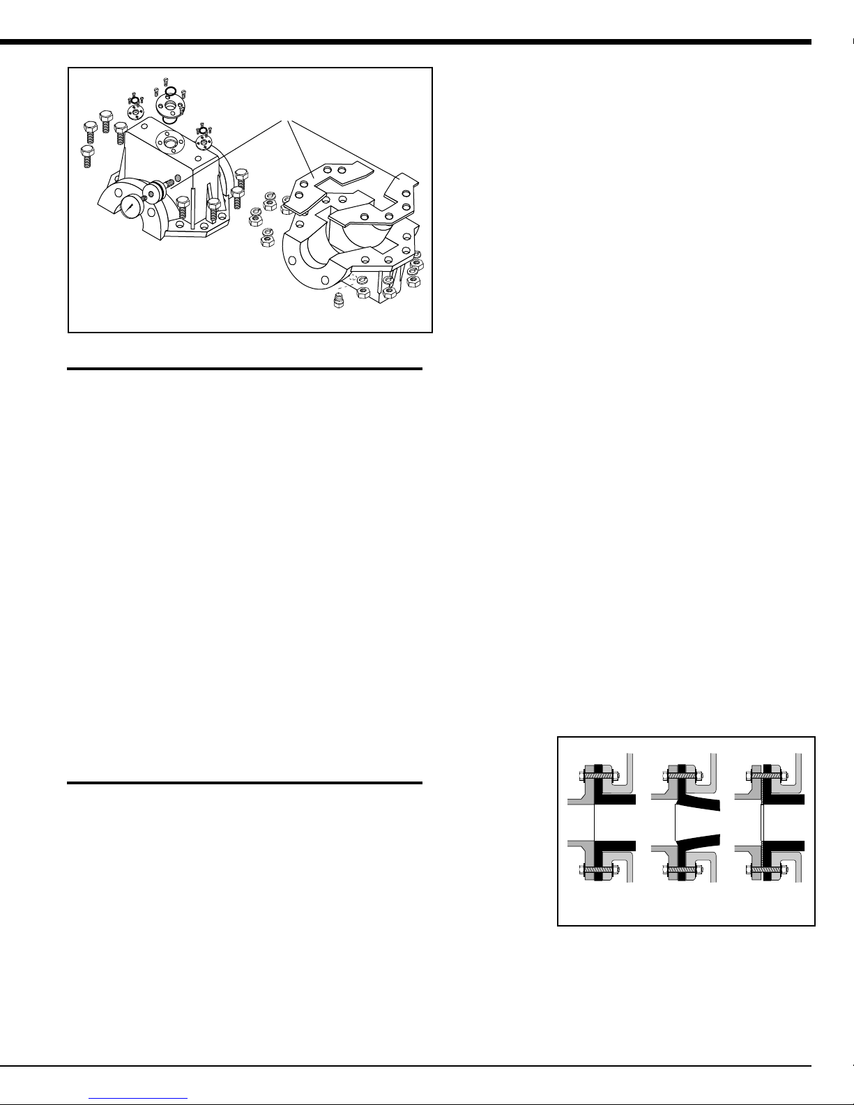
2. The flanges mating to the Series 5400 should be serrated,
approximately 1/16" x 90°. Rubber will creep along smooth
glass, PVC, or Teflon flanges, eventually causing a flange leak.
Flange I.D. should match sleeve I.D. and should be free of
sharp edges which could cut into the sleeve. Weld-neck or
socket flanges are recommended. Slip-on or screw-on
flanges have a larger I.D. and can cut into the rubber. If slip-on
or screw-on must be used, grind off all sharp I.D. edges.
3. Do no use sharp tools such as screwdrivers or crowbars on
the rubber for installation. This can damage the face flange
and cause possible leakage.
4. The valve should be completely open before installing the
valve in the pipeline or tightening flange bolts. Valves with
Fail-Closed spring-return cylinders are shipped with the lower
portion pressurized to keep the valve open during shipment,
storage, and installation. See the supplementary sheet on
installing valves with fail-closed cylinders for more information.
For valves with stem seals and body gaskets,
remove the drain plug in the bottom of the casting
before operating valve.
5. Tighten all flange bolts to values listed in the table on the
back page. You will not overtorque the flange rubber.
6. Pneumatic and hydraulic actuators are sized based upon
the line pressure and operating pressure at the installation
site. Changing the location of the valve may result in insuffi-
cient pressure to fully close the valve, or if the valve has a
fail close spring, it may not fully open. Be sure to refer to the
positioner manufacturerís IOM for proper air line connec-
tions. Connecting plant air to the instrument air port can
result in severe damage.
7. For pneumatic valves, a pressure reducing valve and
integral gauge should be placed on the air supply line and
also on the instrument air supply line. This will prevent
accidental damage to the unit from overpressures or surges.
8. Electrically operated valves are sized based upon the line
pressure and electrical supply available at the installation
site. Only qualified personnel should handle the electrical
connections. Be sure to refer to the actuator manufacturerís
IOM for proper safety precautions. Reversing positive-
negative connections, or connecting the wrong phase power
supply can lead to severe damage.
OPERATION
1.
All units are bench tested before shipping. Calibration
and stroke adjustment may change during shipment. An
operational test is recommended before installing the unit
into the line.
2.
If flanges leak during initial operation, the holes in the
sleeve may be out of line. Open the valve fully, loosen all
flange bolts, stroke the valve half-closed, re-open, and re-
tighten the flange bolts a second time.
3.
For both on-off and modulating valves, be certain that
the sleeve is not slightly cracked open in the fully closed
position. Operating the valve in the cracked position can
shorten sleeve life, since flow velocities are very high
under these conditions. If the valve does not close
completely, it should be adjusted.
For electrically operated valves, the stroke limits and/or
torque limits can be increased to gain additional stroke.
Check the manufacturers operating instructions. For all
valves, the lower pinch bar can be raised slightly to shorten
the stroke.
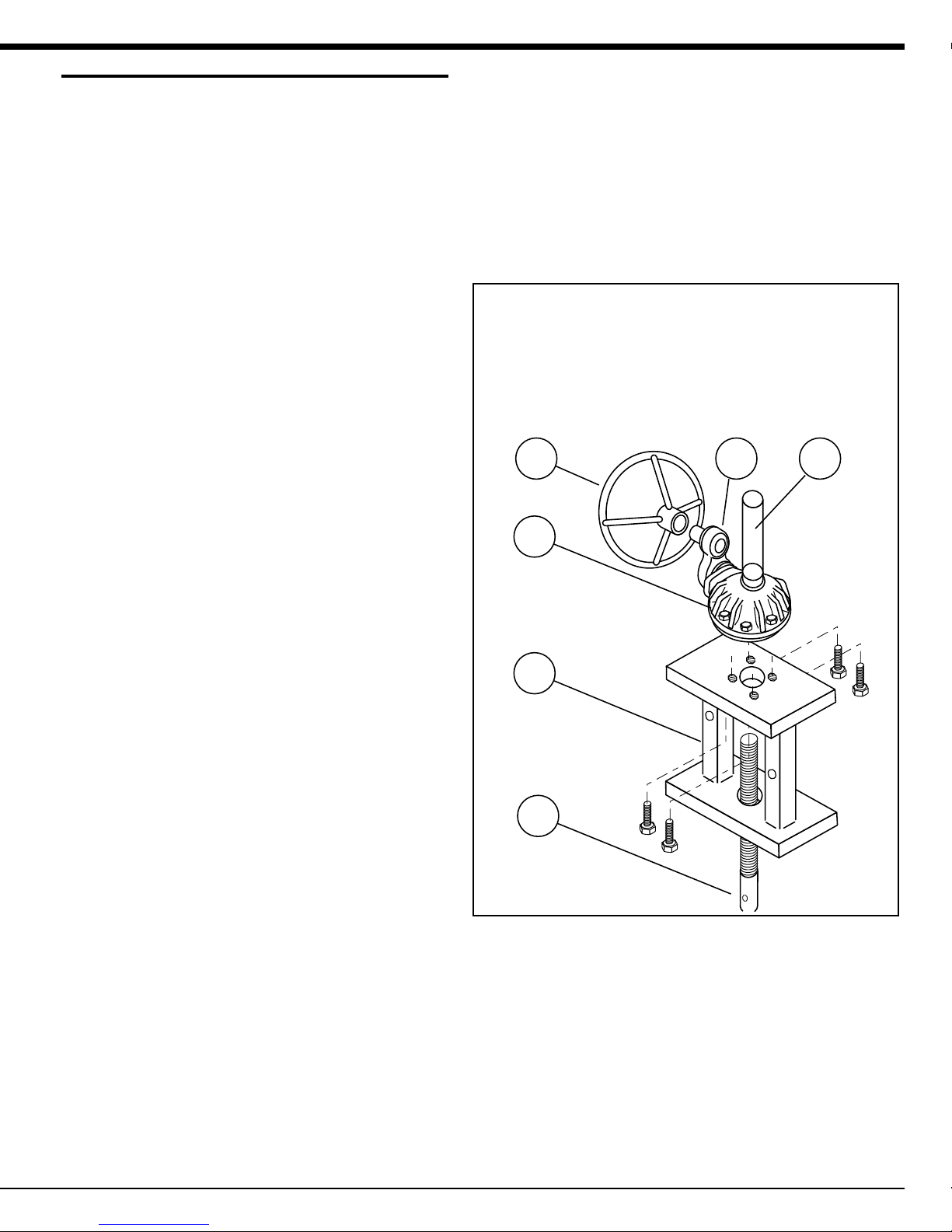
A. With the valve open, remove both Side Rod Pins (6).
B. Close the valve to clear the Scissor Plates (3).
C. Turn each Side Rod clockwise 1-1/2 revolutions.
D. Both bars must be turned the same number of times.
E. Open the valve and reinstall Side Rod Pins (6).
MAINTENANCE
Valves should be inspected, actuated, and lubricated
every 90 days. If the valve is operated under severe
environmental conditions, (eg. high vibration, abrasive
dust, frequent washdown, etc.) the frequency of inspec-
tion, actuation, and lubrication should be increased as
appropriate. Visually examine the operating mechanism
for damage, loose parts or signs of excessive wear.
WARNING: Make sure there is no pressure in
the line before adjusting, tightening, or replac-
ing any parts. Tighten any close parts. Replace any
parts that are damaged or exhibit excessive wear. Lubri-
cate the operating mechanism, side rods, and stem in
the fully closed position using a high quality Lithium based
grease (Mobil Mobilith AW 1 or equivilent). Lubrication is
required at every pivot point on the operating mechanism,
the side rods, and stem. This includes pins, scissor plates,
and the brass bearing blocks. Open the valve and lubri-
cate the operating mechanism, stem, and side rods in the
fully open position. Cycle the valve to the full closed posi-
tion and back to the full open position to distribute the
grease throughout the mechanism.
Page 4 of 8

BEVEL GEAR ACTUATOR
1. DESCRIPTION
For manually operated valves using a bevel gear actua-
tor, the bevel gear is bolted to an actuator mounting
frame, or yoke. The mounting frame is bolted to the
top half of the valve body. The threaded stem passes
through the frame and the bevel gear unit. The threaded
portion of the stem is actuated by a bronze drive nut
inside of the bevel gear. The handwheel or chainwheel is
connected directly to the bevel gear input shaft. In large
line sizes or high pressure applications, a spur gear unit
may be attached to the input shaft, and the handwheel or
chainwheel attached to the spur gear.
2. INSTALLATION
The threaded stem rises through the opening in the
top of the bevel gear. This area must be kept clear of
obstructions. Be sure to open the valve fully before
installing the valve ensure there is sufficient clearance
above the bevel gear for the piston rod to rise.
3. OPERATION
The valve is closed by turning the handwheel clockwise,
and opened by turning the handwheel counterclockwise.
CAUTION: Due to the torque amplifying effect of the
bevel gear, it is possible to overtorque the pinch mecha-
nism, causing damage to the valve.
4. MAINTENANCE
Red Valve Company recommends lubricating the stem
where it is attached to the bevel gear internals every 90
days. The protective cover should be removed and the
valve stem greased liberally with Mobil Mobilith AW 1
or equivalent grease. Be sure to replace the stem cover
securely, or debris could get inside the bevel gear
housing and prevent operation.
The rest of the Dynatorque manual actuator does not
require periodic maintenance. They are lifetime lubricated
with all components designed to have a life equal to or
exceeding the wear life of the gearing. If, for any reason,
lubrication replacement is necessary, Dynatorque recom-
mends replacement with Amoco Amdex No#1 EP or
Exxon Nebula EP1.
5. REMOVAL
To remove the bevel gear unit from the valve, begin by
removing the handwheel or chainwheel by removing the
through bolt that attaches it to the input shaft. Remove all
of the bolts that connect the bevel gear to the mounting
frame. Turn the entire bevel gear counterclockwise. This
will “unscrew” the unit up the piston rod until it can be
removed. Remove the set screw or through bolt that
attaches the handwheel to the input shaft.
2
4 6 5
1
3
1. Bevel Gear
2. Actuator Mounting Frame
3. Threaded Stem
4. Handwheel or Chainwheel
5. Protective Cover
6. Spur Gear (optional)
Page 5 of 8
(Fig. C)
(Fig. C)

REPLACING SLEEVE
1. To remove and replace the sleeve, the entire valve
must be removed from the line. Be sure that the valve is
in the full open position before removing the electrical
supply or air supply. On fail-closed spring-loaded
actuators, air must be trapped in the lower portion of the
cylinder with the ball valve provided. See the supplemen-
tary sheet on installing valves with fail-closed cylinders
for more information.
NOTE: The valve may need to be partially closed during
this procedure. Actuators must have manual overrides,
or access to the required air or electrical supply. If
neither is available, the actuator must be removed. See
the supplementary sheet for your type of actuator for
more information.
2. Remove all body bolts, so that the valve body may be
separated. Lift the top half, with actuator and scissor
mechanism, straight up to expose the sleeve.
3. Remove the screws that hold the lower tabs to the
pinch bar, and the sleeve should move freely enough to
allow access to the upper tabs one at a time. The
actuator may need to be stroked closed to push the
upper pinch bar farther out of the top body half.
4. The old sleeve is removed by bending one flange and
sliding the sleeve through the mechanism.
5. The new sleeve is installed by bending one flange,
sliding the sleeve through the mechanism, and attach-
ing the tabs to the pinch bars. The top half can be
lowered and re-attached to the bottom half. If pro-
vided, be sure that the rubber gasket is in place
between the body halves and does not interfere with
any bolt holes. Do not trim the gasket for length, it is
necessary that the body gaskets extend beyond the
serrated body casting flange.
6. The lower pinch bar may also be removed to make
sleeve replacement easier. Remove the balance bars
and side rod pins before lifting the top half of the body.
Remove the screws that attach the tabs to the lower
pinch bar, and slide the side rods down and out of the
body. After replacing the sleeve and attaching the tabs
to the upper pinch bar, lower the top half of the body,
carefully guiding the side rods through the brass guides.
MECHANISM ASSEMBLY
If the scissor mechanism is removed for any reason, it is
important that it is re-assembled in the correct order.
(See Fig.E)
1. Place Mounting Frame (5) onto the top of the valve
body. If pattern of small holes in the bottom plate does
not line up with holes on the top of the valve, Mounting
Frame (5) must be turned over. Secure with bolts. The “legs”
of the Mounting Frame (5) are offset. Orient yourself at the front
of the valve. (Fig.D)
2. Slide one Pivot Pin (7) into each leg of the Mounting Frame
(5). Slide one Side Rod Pin(6) into each Side Rod(2). On the
FRONT Side Rod Pin (6), slide the thick Spacer (10) onto the
LEFT side of the Side Rod Pin (6), and the thin Spacer (10) onto
the RIGHT side. On the REAR Side Rod Pin (6), the thin Spacer
(10) goes onto the LEFT side, the thick Spacer (10) goes onto
the RIGHT side.
3. The first Scissor Plate (3) is placed at the FRONT, on the
RIGHT side. Slide hole in the center of the plate over the Pivot
Pin (7). The Side Rod Pin (6) should protrude through one of the
slots. One Brass Guide (9) is slid onto the Side Rod Pin (6) and
into the slot. Another Brass Guide (9) is placed into the upper
slot for later use. The second Scissor Plate (3) is installed in the
same manner on the REAR RIGHT Side. Repeat the procedure
for the LEFT side Scissor Plate (3), beginning with the REAR
plate first, and then the FRONT plate. Secure the Scissor Plates
(3) with a NUT(12) on each end of the Pivot Pins (7).
4. Insert the Stem Pin (8). Place a Brass Guide (9) into the
RIGHT outer plate, slide the Stem Pin (8) through both Brass
Bearing Blocks (9) on the RIGHT side. Raise the Stem (1) until
the Stem Pin (8) aligns with the hole in the Stem (1). The Center
Pin (1) can then be slid through the Brass Guide (9) in the inner
plate on the LEFT side, and a Brass Guide (9) can be added to
the outer plate. Secure the Stem Pin (8) with a Threaded Spacer
(11) on each side.
5. Notice that each Spreader Bar (4) has a spacer block at each
end, one thick, and one thin. Slide the Spreader Bar (4) onto the
Side Rod Pins (6) and secure with a Nut (12).One the RIGHT
Side, The thick spacer goes towards the FRONT, and the thin
spacer goes towards the REAR. Repeat the procedure for the
LEFT side, placing the thick spacer to the REAR and the thin
spacer to the FRONT. Once all parts have been assembled,
secure all three rods by adding a second Nut (12) and tighten.
Secure with a fastening compound such as Lock-Tite.
(Fig. D)
Rear
Front
Right Left
Page 6 of 8

(Fig. E)
2
2
1
12
12
3
3
10
10
10
11
6
7
6
5
7
9
9
4
4
12
8
Page 7 of 8
See Page 2 of 8 for
parts list.

SERIES 5400 FLANGE BOLTING SPECIFICATIONS
VALVE NO. OF BOLT CIRCLE THREAD A B BOLT TORQUE
SIZE BOLTS DIAMETER SIZE (ft. lbs)
1
"
4 3-1/8
"
1/2
"
- 13 NC 1/2
"
3/4
"
20
1-1/2
"
4 3-7/8
"
1/2
"
- 13 NC 1/2
"
5/8
"
25
2
"
4 4-3/4
"
5/8
"
- 11 NC 1/2
"
3/4
"
40
2-1/2
"
4 5-1/2
"
5/8
"
- 11 NC 1/2
"
3/4
"
50
3
"
46
"
5/8
"
- 11 NC 1/2
"
3/4
"
55
4
"
8 7-1/2
"
5/8
"
- 11 NC 3/8
"
7/8
"
40
5
"
8 8-1/2
"
3/4
"
- 10 NC 3/8
"
–
"
50
6
"
8 9-1/2
"
3/4
"
- 10 NC 5/8
"
7/8
"
60
8
"
8 11-3/4' 3/4
"
- 10 NC 1
"
1
"
70
10
"
12 14-1/4
"
7/8
"
- 9 NC 1/2
"
1
"
70
12
"
12 17
"
7/8
"
- 9 NC 5/8
"
1-1/4
"
75
14
"
12 18-3/4
"
1
"
- 8 NC 1
"
1-3/8
"
100
16
"
16 21-1/4
"
1
"
- 8 NC 1
"
1-7/16
"
70
18
"
16 22-3/4
"
1-1/8
"
- 7 NC 1-1/2
"
1-5/8
"
55
20
"
20 25
"
1-1/8
"
- 7 NC 1-1/2
"
1-3/4
"
50
24
"
20 29-1/2
"
1-1/4
"
- 7 NC 1-1/2
"
2
"
70
5200 IOM 5/97
Page 8 of 8
WARRANTIES - REMEDIES - DISCLAIMERS - LIMITATION OF LIABILITY
Unlessotherwiseagreedto inwritingsignedbyRedValve, allProducts
suppliedbyRedValvewillbedescribedinthespecificationssetforthon
the face hereof.
THE WARRANTIES SET FORTH IN THIS PROVISION ARE EXCLU-
SIVEANDINLIEUOFALLOTHERWARRANTIESWHETHERSTATU-
TORY, EXPRESS OR IMPLIED (INCLUDING ALL WARRANTIES OF
MERCHANTABILITYANDFITNESSFORAPARTICULARPURPOSE
ANDALLWARRANTIESARISINGFROMCOURSEOFDEALINGOR
USAGE OR TRADE).
Red Valve Products are guaranteed for a period of one year from date
of shipment, against defective workmanship and material only, when
properly installed, operated and serviced in accordance with Red
Valve's recommendations. Replacement for items of Red Valve's
manufacturewill bemade freeofcharge ifprovedtobe defectivewithin
such year; but not claim for transportation, labor or consequential
damages shall be allowed. We shall have the option of requiring the
returnofthedefectiveproducttoourfactory,withtransportationcharges
prepaid, to establish the claim and our liability shall be limited to the
repair or replacement of the defective product, F.O.B. our factory. Red
Valve will not assume costs incurred to remove or install defective
products nor shall we incur backcharges or liquidated damages as a
result of warranty work. Red Valve does not guarantee resistance to
corrosion erosion, abrasion or other sources of failure, nor does Red
Valve guarantee a minimum length of service, or that the product shall
be fit for any particular service. Failure of purchaser to give prompt
writtennotice ofany allegeddefectunder thisguaranteeforthwithupon
itsdiscovery, oruse, andpossession thereofafteran attempthas been
made and completed to remedy defects therein, or failure to return
product or part for replacement as herein provided, or failure to install
andoperatesaidproductsandpartsaccordingtoinstructionsfurnished
by Red Valve, or failure to pay entire contract price when due, shall be
a waiver by purchaser of all rights under these representations. All
orders accepted shall be deemed accepted subject to this warranty
whichshall beexclusiveof anyother orpreviouswarranty, andshallbe
theonlyeffectiveguaranteeorwarrantybindingonRedValve,anything
on the contrary contained in purchaser's order, or represented by any
agentoremployeeofRedValveinwritingorotherwise,notwithstanding
implied warranties. RED VALVE MAKES NO WARRANTY THAT THE
PRODUCTS, AUXILIARIES AND PARTS ARE MERCHANTABLE OR
FIT FOR ANY PARTICULAR PURPOSE.
RED VALVE WARRANTYRED VALVE WARRANTY
RED VALVE WARRANTY
A. Standard pinch valves are
built to schedule 40 pipe I.D.
and to ANSI Class 125/150#
flange and bolt circle specifica-
tions. It is recommended that
the mating flanges are flat and
full faced.
B. It is recommended that the
mating flange be serrated to
"grip" the rubber flange. The
serrations should be cut 1/16"
deep, with a 90 angle tool
point. the pitch should be 8
(eight) cuts per inch.
C. Mating flange ID must match
the pinch valve
sleeve ID.
D. When installing a pinch
valve to a rubber, PVC, or any
"slick" mating flange, we
recommend that you install a
metal serrated gasket between
the two flanges to assist in
the seal.
E. When bolting a pinch valve
to a PVC or synthetic mating
flange, use a split back-up
retaining ring, since the mating
flange will yield prior to
generating enough force on the
flange faces for a proper seal.
F. Torque all the flange bolts in
a star pattern, first to 50% of
tabulated valves, then retorque
to 100% of tabulated valves. If
greater torque is required,
continue retorquing in incre-
ments of 50% of tabulated
valves. Use of high quality anti-
seize compound on all bolt
threads is recommended.
Variables such as the surface finish on bolt threads, type of
anti-seize compound used, and surface finish of the mating
flanges all have an effect on the minium torque required to
obtain a leak-tight flange seal.
A.
B.
C.
D.
E.
F.
1/16"
90
D1 = D2
1
2
3
4
5
6
78
Control Pinch
Valve Body
A B
Rubber
Sleeve
Pipeline Flange
Weldneck is preferred so
that I.D. of flange matches
that of rubber sleeve
Table of contents
Popular Control Unit manuals by other brands

CubuSynth
CubuSynth Exhaust V2 user manual

Colby Instruments
Colby Instruments PDL-200A-625PS Operating and programming manual

Massoth
Massoth DiMAX 280R manual

Dungs
Dungs MB-ZR B07 Series instructions

National Instruments
National Instruments NI 9469 Getting started guide

Pepperl+Fuchs
Pepperl+Fuchs VAA-2E-KE1-S Original instructions