RedBack Lasers LLRMM30 User manual

Thank you very much for purchasing
RedBack LLRMM30 line laser ranging
detector. LLRMM30 Receiver
I. Feature & Function
II. User Security
III. Instrument Structure
IV. Operation Manual
V. Technical Specifications
VI. Maintenance
VII. Packing List

1
I. Feature & Function
LLRMM30 laser ranging detector is an
essential accessory for line lasers to detect
the position of the laser signal emitted by the
line lasers. Used in conjunction with the line
laser to give horizontal and vertical
reference plane quickly and accurately.
※Digital display the laser line position
exactly;
※Large detecting window;
※TFT LCD and high-brightness LED
display simultaneously;
※Ranging function
※Suitable for various types of line lasers
Both red and green lasers can be used;
※Strong magnetic attachment function.
II. User Security
Do not disassemble the instrument
and perform internal repairs. Repairs

2
can only be made through an
authorized service center.
Make sure the instrument is in place.
III. Instrument Structure
Long blister
Upper
indicator
LCD
display
Receiving
window
keypad
center
Lower
indicator

3
Power:switch
on/off; fine/coarse
measurement switch:
short press to switch to
detection accuracy/ long
Figure
1
Figure
2
Round
magnet
buzzer
Clamp
postioning
hole
Battery
flap
Safety
label
Round
magnet
Side
LED
indicator
nut
Long
magnet
Top
round
blister
Ranging
receiving
window
Ranging
emitting
window
screw
Bottom
round
blister

4
press to switch between
short and long distance;
sound/unit switch:
short press switch buzzer
function/ long press
switch to unit;
Ranging reference
selection: short press to
switch the ranging
reference;
Mode: Short press toswitch area measurement,
volume measurement, Pythagorean 1
measurement, and
Pythagorean 2 measurement;
Ranging button: lit the laser/single ranging;
Clear: clear data or exit the current state;
Automatic: enter the automatic measurement
subroutine.
IV. Operation Manual

5
1. Switch on/off
Press once, the LCD displays the instrument
model and version number (Figure 3), the
LED indicator lights up from top to bottom
and then goes out ; the buzzer emits a “didi”
power-on prompt, and then enters the
normal detection state. Shown in Figure 4.
Figure 3 Figure 4
2. Detection accuracy mode selection
Short press the key in the power-on
state, and the instrument will switch

6
between fine measurement (±1mm) and
coarse measurement (±3mm) modes. The
detection accuracy indicator on the LCD is
shown in the figure below.
As shown in the figure: the top one is the fine
measurement, the bottom one is the coarse
measurement;
Figure 5
3. Short/long distance mode selection
When the instrument is turned on, the
instrument is in the long-range mode, if you
want to receive strong signals, you need to
hold down the key to switch to the
short-range mode to receive signals; There
are text prompts at the top left of the screen:
Far, Near.

7
4. Sound state selection
Short press the key in the power-on
state, and the instrument will switch
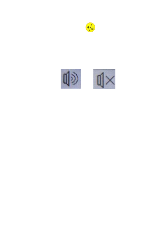
between sound and silent state. The sound
indicator on the LCD is as shown in the
figure below.
Figure 6
sound silent Prompt: The
sound and silent state is for the sound
indication when receiving; the key tone will
not be turned off;
5. LCD backlight function
The lighting is on when it is turned on, and
the backlight of the round blister is also
turned on. If the laser signal is not received
within 2 minutes, and there is no key
operation, the backlight will automatically go
out. Once the laser signal is received, or

8
there is a button operation, the backlight will
automatically turn on.
6. Value display & unit switch function
Long press to switch the value unit.
On the left corner of the screen displays:M, Ft.
M means meters, and Ft means foot.
7. Posture recognition and display flip
When the instrument is used upside
down, the instrument will automatically
recognize the posture and turn the display
on the LCDupside down to facilitatethe user
to read the indication status and measured
value;
8. Laser detection
The meaning ofthe information displayed on
the LCD when the instrument detects the
laser is as follows:

9
a. The laser line is on the upper part of
the zero position, and the lower indicator
LED is long on, and the instrument emits a
quick short tone.
Example: The laser line is emitting 1mm
above the zero line, the LCD displays an
upward arrow, and the
offset distance value
is 1mm.
Figure 7
b. The laser line is at the bottom of the
zero position, the upper indicator LED is on,
and the instrument emits a slow short tone.

10
c. The laser line coincides with the
zero position, the centered LED is on, and
the instrument emits a long beep.
Note: When the distance between the laser
level and LS723 is less than 1 meter, it may
cause the display position to be abnormal.
Please use it when the distance is greater
than this.
9. Ranging function
After the instrument is turned on, it enters
the regular measurement page, and the
ranging module is in working state;
9.1 Setting the measurement
reference
Short press to switch the measurement
datum; it can switch among the 3 datum

11
planes: upper end surface, zero line, lower
end surface, etc.;
Upper end zero line lower end Figure
8
9.2 Single measurement
Press the key for the first time to light up
the laser dot(Figure 9), aim at the target with
the laser dot, and press again to
measure the distance; the distance
measurement result is displayed on the first
row;
If the distance measurement operation is
performed again, the distance value of the
first row will automatically move to the next
row, and the new value will be displayed in
the first row, as shown in Figure 10. When

12
the distance measurement is performed
multiple times, the latest distance value is
always in the first row; Simultaneously
display the results of the last 5 distance
measurements;
Operate to clear the last ranging result;
Laser dot lit up
Figure 9 Figure 10
9.3 Area measurement

13
9.3.1 Short press the key once in the
routine measurement to enter the area
measurement, as shown in Figure 11; press
the key to light up the laser, and press
the key to clear the last
measurement;
Figure 11 Figure 12
9.3.2 First measure the first edge, the
measurement result is shown in Figure 12;
9.3.3 Then measure the
second edge, and the
measurement result will be
displayed on the second

14
row; the instrument will automatically
calculate the areavalue and display it on the
third row, as shown in
Figure 13;
Figure 13
9.4 Volume measurement
9.4.1 Short press the key twice in the
routine measurement to enter the volume
measurement, as shown in Figure 14; press
the key to light up the laser, and press the
key to clear the last
measurement;
9.4.2 First measure the first edge, and the
measurement result is displayed on the first
row, as shown in Figure 15;
9.4.3 Then measure the second edge, and
the measurement result is displayed on the
second row, as shown in Figure 16;

15
9.4.4Finallymeasure thethird edge,andthe
measurement result is displayed in the third
row; the instrument will automatically
calculate the volume value and display it in
the fourth row, as shown in Figure 17;
Figure 14 Figure 15
Figure 16
Figure
1
7

16
9.5 Pythagorean 1 measurement
9.5.1 Short press the key three times in
the routine measurement to enter the
Pythagorean 1 measurement, as shown in
Figure 18; press the key to light up the
laser, and press the key to clear the last
measurement;
9.5.2 First measure the first side a
(hypotenuse), the measurement result is
displayed on the first row, see Figure 19;
9.5.3 Then measure the second side b
(right-angle side), and the measurement
result will be displayed on the second row;
the instrument will automatically calculate
the value of the third side x and display it on
the third row, as shown in Figure 20;

17
Figure 18
Figure 19 Figure 20
9.6 Pythagorean 2 measurement
9.6.1 Short press the key four times in
the routine measurement to enter the
Pythagorean 1 measurement, as shown in
Figure 21; press the keyto light

18
up the laser, and press the keyto clear the
last
measurement;
Figure 21
Figure 22 Figure 23 Figure 24
9.6.2 First measure the first side a
(hypotenuse), and the measurement result

19
is displayed in the first row, as shown in
Figure 22;
9.6.3 Then measure the second side
b (right-angled side), and the measurement
result is displayed in the second row, as
shown in Figure 23;
9.6.4 Finally measure the third side c
(hypotenuse), and the measurement result
is displayed in the third row; the instrument
will automatically calculate the value of the
fourth side x and display it in the fourth row,
as shown in Figure 24;
Tip: When measuring Pythagorean 1 and
Pythagorean 2, the hypotenuse should be
larger than the right angle, otherwise an
error beep will sound and the measured
value will be discarded;
9.7 Automatic measurement
Table of contents
Other RedBack Lasers Receiver manuals