manuals.online logo
Brands
  1. Home
  2. •
  3. Brands
  4. •
  5. Redback
  6. •
  7. Amplifier
  8. •
  9. Redback A 4931 User manual

Redback A 4931 User manual

Redback® A 4928 Line Output Box
Operating Manual
A 4928 Line Output Box
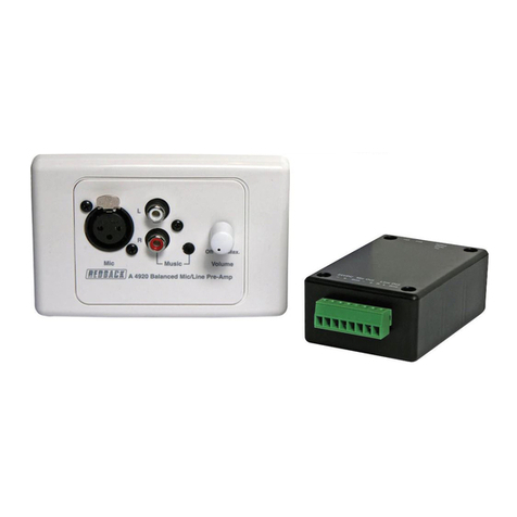
A 4931 Mic/Line Preamp Wallplate
A 4932 Mic/Line Preamp Box
OVERVIEW
The Redback®A 4931 remote mic/line pre-amp wallplate or the Redback®A 4932 remote mic/line pre-amp box accepts
either a microphone or line input for conversion to a balanced high level signal. Mic input is via a balanced XLR whilst the
line input is via 2 x RCA sockets or 3.5mm jack.
The 3V output signal is carried via Cat5e cable (suitable for distribution up to 300m without interference) to the Redback®
A 4928 Line Output box which provides a balanced high or low level output and an unbalanced Aux output signal to be
fed into an amplier.
Power is supplied via the included 24V Plugpack which is connected to the Redback®A 4928 Line Output box. Power for
the Redback®A 4931 mic/line pre-amp wallplate or the Redback®A 4932 mic/line pre-amp box is provided through the
Cat5e cable connection.
The Redback®A 4928 has a 24V DC switched output (limited to 120mA current draw) which activates when the VOX
output of the Redback®A 4931 or Redback®A 4932 is active.
User manual revision number: 1.0 25/06/2019
A 4931
A 4932
A 4928
www.redbackaudio.com.auRedback® Proudly Made In Australia2
Redback® A 4928 Line Output Box
CONNECTIONS
Figures 1 and 2 illustrate typical wiring congurations for the Redback® A 4928 Line Out Box connections to the Redback®
A 4931 mic/line pre-amp wallplate or Redback®A 4932 mic/line pre-amp box. Connection is made via a Cat5e/6 cable
with a maximum run distance of 300 metres. The audio from the A 4931 or A 4932 is fed down the cable to the A 4928
and power is fed back from the A 4928 to power the A 4931 or A 4932. The A 4928 is powered by the supplied 24V DC
plugpack or by any other 24V DC source which can be connected to the 24V DC input euro block.
There are two available outputs from the A 4928 which include a Line level Unbalanced output and a Balanced output which
can be either Mic or Line level depending on the DIP switch 2 setting of the A 4928 (see DIP Switch settings).
Fig 1. Fig 2.
24V DC SWITCHED OUTPUT
The Redback®A 4928 has a 24V DC switched output (limited to 120mA current draw) which activates when the VOX circuit
of the Redback®A 4931 or Redback®A 4932 is active.
Note 1: DIP switch 1 of the A 4928 must be set to ON to enable the switched output option.
Note 2: DIP switch 3 of the A 4931 or A 4932 must also be set to ON to enable the VOX output.
Mic
R
L
21
3
Mic Music
R
L
Volume
0
2
46
8
10
Cat5e max. 300m
24V DC Plugpack
(Supplied)
Amplifier
Balanced mic/line
Unbalanced line
OR
Microphone
CD Player, Tuner etc
Media Player,
Mobile Phone etc
A 4931 Mic/Line
Preamp Wallplate
A 4928 Line Output Box
A 4928 Line Output Box to
A 4931 Mic/Line Preamp Wall Plate Connection Diagram
Cat5e max. 300m
24V DC Plugpack
(Supplied)
Amplifier
Balanced mic/line
Unbalanced line
OR
MicrophoneCD Player, Tuner etc
Media Player,
Mobile Phone etc
A 4932 MIc/Line
Preamp Box
A 4928 Line Output Box
A 4928 Line Output Box to
A 4932 Mic/Line Preamp Box Connection Diagram
MicVoxActive
L
R
Timer
Mic/line Preamp
A 4932
Music
21
3
Redback® A 4928 Line Output Box
www.redbackaudio.com.au Redback® Proudly Made In Australia 3
Redback® A 4928 Line Output Box
A 4928 DIP SWITCH SETTINGS
DIP SW 1: ON - 24V DC switched output option active
DIP SW 2 (Balanced Output): ON - High Level output, OFF - Low level output
DIP SW 3: Not Used
DIP SW 4: Not Used
A 4931 and A 4932 DIP SWITCH SETTINGS
The A 4931 and A 4932 have a set of DIP switches on the rear which determine how the audio is output.
The DIP switches are labelled 1) VOX BOTH, 2) VOX ENABLE, 3) VOX OUTPUT.
When the A 4931 or A 4932 is used with the A 4928 there are four possible audio output options.
1) Mixed OUT (No switched Output) - The audio from the A 4931/32 microphone input and the line and/or music inputs
are mixed together and output to the A 4928. The VOX Output is inactive.
DIP Switches set as follows: 1-OFF ,2-OFF, 3-OFF
2) Mixed OUT (With switched Output) - The audio from the A 4931/32 microphone input and the line and/or music
inputs are mixed together and output to the A 4928. The VOX Output (and hence the Switched Output) is enabled.
DIP Switches set as follows: 1-ON ,2-OFF, 3-ON
3) Mic Priority Over Line/Music Inputs (No switched Output) The A 4931/32 microphone input has VOX priority over
the line and music inputs. I.e. the audio from the line/Music inputs will be over ridden by the MIc input when a microphone
is used. The VOX Output is inactive.
DIP Switches set as follows: 1-OFF ,2-ON, 3-OFF.
4) Mic Priority Over Line/Music Inputs (With switched Output) The A 4931/32 microphone input has VOX priority over
the line and music inputs. I.e. the audio from the line/Music inputs will be over ridden by the MIc input when a microphone
is used. The VOX Output (and hence the Switched Output) is enabled.
DIP Switches set as follows: 1-OFF ,2-ON, 3-ON.
The VOX sensitivity of the microphone is adjusted by the trimpot on the rear of the A 4931 and A 4932 labelled “VOX” or
“VOX sensitivity”.
DIP SWITCHES
VOX SENSITIVITY
Fig 4 - A 4931 DIP switches and VOX sensitivity adjustment location.
DIP Switches
VOX
Sensitivity
DIP Switches
Fig 5 - A 4932 DIP switches and VOX sensitivity adjustment location.
Fig 3 - A 4928 DIP switches location.
www.redbackaudio.com.auRedback® Proudly Made In Australia4
Redback® A 4928 Line Output Box
A 4928 Specications
UNBALANCED OUTPUT SENSITIVITY: ...............................1V
BALANCED OUTPUT SENSITIVITY: .......................... 3mV/1V
INPUT CONNECTORS: ...................................... RJ45 8P8C
24V DC Power :..............2.1mm JACK (centre +ve)
...................... Euroblock terminals
OUTPUT CONNECTORS:
Unbalanced AUX Out: ............ Euroblock terminals
Balanced Output: .................... Euroblock terminals
24V DC Switched Out: ............ Euroblock terminals
AUDIO : .......................3 pin XLR balanced
DIMENSIONS:≈...................................... 130W x 95D x 28H
WEIGHT: ≈................................................................ 0.2 kg
A 4931 Specications
INPUT MIC LEVEL SENSITIVITY:......................................3mV
INPUT LINE LEVEL SENSITIVITY:.........................................1V
MUSIC INPUT LEVEL SENSITIVITY: .............................200mV
OUTPUT CONNECTOR: ...................................... RJ45 8P8C
INPUT CONNECTORS:
AUDIO : .......................3 pin XLR balanced
....................................... 2 x RCA
............................... 3.5mm JACK
A 4932 Specications
INPUT MIC LEVEL SENSITIVITY:......................................3mV
INPUT LINE LEVEL SENSITIVITY:.........................................1V
MUSIC INPUT LEVEL SENSITIVITY: .............................200mV
OUTPUT CONNECTOR: ...................................... RJ45 8P8C
INPUT CONNECTORS:
AUDIO : ......................3 pin XLR balanced
....................................... 2 x RCA
............................... 3.5mm JACK
DIMENSIONS:≈...................................... 133W x 65D x 44H
WEIGHT: ≈................................................................ 0.2 kg
All Australian made Redback products are covered by a 10 year warranty.
Should a product become faulty please contact us to obtain a return authorisation number. Please ensure you have all the
relevant documentation on hand. We do not accept unauthorised returns. Proof of purchase is required so please retain
your invoice.
Distributed by Altronic Distributors Pty. Ltd. Perth. Western Australia.
Phone: 1300 780 999 Fax: 1300 790 999 Internet: www.altronics.com.au
RJ45 cabling conguration for system components (586A ‘Straight through’)
System components are connected using “pin to pin” conguration RJ45 data cabling as shown below. When installing
ensure all connections are veried with a LAN cable tester before switching any system component on.
Failure to follow the correct wiring conguration may result in damage to system components.
Troubleshooting
NO Power (Power LED does not illuminate):
Check power supply DC jack is 2.1mm and not 2.5mm size.
Check polarity of 24V DC supply.
A 4931 Wallplate or A 4932 not operating correctly:
Check RJ45 cabling is correct.
586A
1 TX+
2 TX-
3 RX +
4
5
6 RX-
7
8
StraightThrough
(both ends)
Pins Face Upwards
1 TX+
2 TX-
3 RX +
4
5
6 RX-
7
8

Other manuals for A 4931

2

This manual suits for next models

2

Other Redback Amplifier manuals

Redback A 4230 User manual

Redback

Redback A 4230 User manual

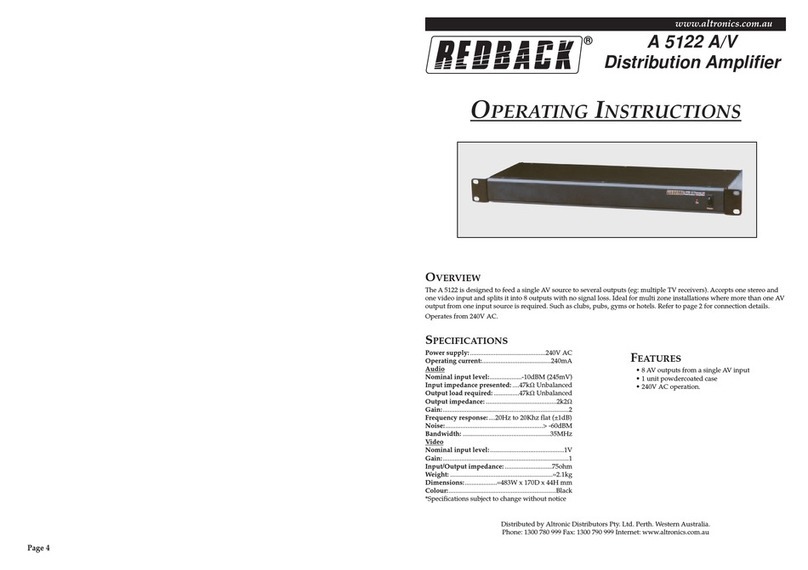
Redback A 5122 User manual

Redback

Redback A 5122 User manual

Redback A 4270 User manual

Redback

Redback A 4270 User manual

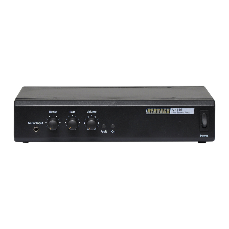
Redback A 4116 User manual

Redback

Redback A 4116 User manual

Redback A 4860 User manual

Redback

Redback A 4860 User manual

Redback A 1937 User manual

Redback

Redback A 1937 User manual

Redback A 4370A User manual

Redback

Redback A 4370A User manual

Redback A 4036 User manual

Redback

Redback A 4036 User manual

Redback A 4230A User manual

Redback

Redback A 4230A User manual

Redback PHASE 5 A 4264 User manual

Redback

Redback PHASE 5 A 4264 User manual

Redback A4260B User manual

Redback

Redback A4260B User manual

Redback A 4235 User manual

Redback

Redback A 4235 User manual

Redback A4260 User manual

Redback

Redback A4260 User manual

Redback A 4377 User manual

Redback

Redback A 4377 User manual

Redback A 4031C User manual

Redback

Redback A 4031C User manual

Redback A 4024 User manual

Redback

Redback A 4024 User manual

Redback A 2082 User manual

Redback

Redback A 2082 User manual

Redback A 4582 User manual

Redback

Redback A 4582 User manual

Redback A 1922A User manual

Redback

Redback A 1922A User manual

Redback A 4262B User manual

Redback

Redback A 4262B User manual

Redback A 4020A User manual

Redback

Redback A 4020A User manual

Redback A 1116 User manual

Redback

Redback A 1116 User manual

Redback A 4937 User manual

Redback

Redback A 4937 User manual

Redback A 4314 User manual

Redback

Redback A 4314 User manual

Popular Amplifier manuals by other brands

DAPAudio PA-250 manual

DAPAudio

DAPAudio PA-250 manual

Crystal Vision Indigo MADDA 105 user manual

Crystal Vision

Crystal Vision Indigo MADDA 105 user manual

Global Invacom Loftbox installation guide

Global Invacom

Global Invacom Loftbox installation guide

Acoustic APDI user manual

Acoustic

Acoustic APDI user manual

Fosgate Audionics Signature owner's manual

Fosgate Audionics

Fosgate Audionics Signature owner's manual

Carver Professional PM-900 owner's manual

Carver Professional

Carver Professional PM-900 owner's manual

Octava HDDA34-V1.3 installation guide

Octava

Octava HDDA34-V1.3 installation guide

Luxman 5M20 Service manual

Luxman

Luxman 5M20 Service manual

NXP Semiconductors BGU7008 user manual

NXP Semiconductors

NXP Semiconductors BGU7008 user manual

Onkyo M-588F Service manual

Onkyo

Onkyo M-588F Service manual

X-PROGRAM X-D11 How to install and operate

X-PROGRAM

X-PROGRAM X-D11 How to install and operate

Ltc Audio ATM7000USB manual

Ltc Audio

Ltc Audio ATM7000USB manual

Reloop AMPEROR-4000 Operation manual

Reloop

Reloop AMPEROR-4000 Operation manual

Stanford Research Systems SIM954 Operation and service manual

Stanford Research Systems

Stanford Research Systems SIM954 Operation and service manual

Ground Zero GZCA 3.0SPL-M1 owner's manual

Ground Zero

Ground Zero GZCA 3.0SPL-M1 owner's manual

Crest Audio FXA4801 Specifications

Crest Audio

Crest Audio FXA4801 Specifications

ORTEC 570 Operating and service manual

ORTEC

ORTEC 570 Operating and service manual

Pioneer VSA-1000 operating instructions

Pioneer

Pioneer VSA-1000 operating instructions

manuals.online logo
manuals.online logoBrands
  • About & Mission
  • Contact us
  • Privacy Policy
  • Terms and Conditions

Copyright 2025 Manuals.Online. All Rights Reserved.