manuals.online logo
Brands
  1. Home
  2. •
  3. Brands
  4. •
  5. Redback
  6. •
  7. Amplifier
  8. •
  9. Redback A 4031B User manual

Redback A 4031B User manual

Operating Manual
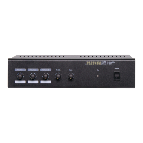
A 4031B 30 Watt Public Address Amplifier
A 4033B 30 Watt Public Address Amplifier Rack Mount
Redback®Proudly Made In Australia
IMPORTANT NOTE:
Please read these instructions carefully from front to back prior to installation. They include important setup instructions.
Failure to follow these instructions may prevent the system from working as designed.
®
A 4031B
A 4033B
2Redback®Proudly Made In Australia
FEATURES
• 3 Inputs suitable for either microphone or line level, or for use as microphone and line level coupled together. disc, cassette, tuner, etc.
• Bass and treble controls (on both microphone and auxiliary inputs).
• Full 30W RMS output (100V and 4 -16Ωoutputs).
• Push to talk muting.
• Protection against over-voltage, over current, thermal run-away and short circuit load.
• Internationally accepted IEC mains socket (240V AC operation only).
• Stereo RCA sockets for all auxiliary inputs (configured to mono internally allowing standard stereo equipment to be directly connected).
• Fully balanced microphone inputs.
• Tape output, suitable for recording, or for connection to a second amplifier.
• Ten year warranty.
CONNECTIONS
Microphone 1
There are three types of sockets on the rear of the amplifier for microphone one. These are 6.35 mm (unbalanced) jack, 5 pin din, or 3 pin XLR
female. The 5 pin din has facility for PTT (push to talk) muting. The PTT contacts will mute input 2 (mic 2 and aux 2) and input 3 (mic 3 and
aux 3). The PTT contacts will not mute Aux 1 input. Wiring for 5 pin din socket is as per Fig 1. We recommend that you connect only one
microphone at a time to input 1.
For connection to the 3 pin XLR sockets refer to Fig 2.
Microphones 2 and 3
These are via 3 pin XLR sockets. Refer to Fig 2 for wiring these.
Speaker Outputs
Screw terminals are provided for both VC (voice coil) and 100V outputs. Minimum impedance for 100V loads is 333Ω(When only the 100V
output is used).Minimum impedance when only VC output is used is 8-16Ω@ 30W total load. A combination of 100V and VC is possible how-
ever we do not recommend this. If more than 30W is used then the unit may shut down due to overloading.
Tape Out
This is a mono output configured for a stereo lead for direct connection to a stereo source. This is suitable for connection to an auxiliary input
on external equipment. This is also suitable for driving 600Ωloads.
JP1 JP2
Configuration 1
When both jumpers are set to the outside the following logic applies...
•When paging through input 1, the VOX switch (where fitted) mutes
both inputs 2 and 3.
•When the PTT contacts on input 1 are closed, both inputs 2 and 3
are muted.
•Paging through input 2 or input 3 has no effect on any other input.
Note
1-There is no PTT facility on inputs 2 and 3.
2 - The PTT facility on microphone 1 will not mute Aux.1.
Configuration 2
When both jumpers are set to the inside the following logic applies...
• When paging through input 2, the VOX switch mutes input 3.
• When the PTT contacts on input 1 are closed, input 3 is muted.
• Paging through input 3 has no effect on any other input.
Note
1 - There is no PTT facility on inputs 2 and 3.
2 - There is no priority between input 1 and input 2 in this
configuration, i.e. paging on both inputs 1 and 2 simultaneously will
mean they mix together.
INTERNAL JUMPER SETTINGS
The amplifier has 3 sets of internally selectable jumpers, located as per figure 3.
VOX Muting Adjustments
VOX can be selected ON or OFF on the board via JP3.
1-VR1 adjusts the VOX sensitivity (i.e. input level that will activate switch). Turning the trimpot anticlockwise (as viewed from top) will make the
VOX switch less sensitive. This will prevent unwanted activation due to high ambient (background noise).
2 - VR2 adjusts the tail length (i.e. time before switching off) of the VOX switch. Turning VR2 anti-clockwise will increase the tail length.
Important Note: There are only two combinations of jumper settings for JP1 and JP2:
• Configuration 1: both jumpers set to the outside
• Configuration 2: both jumpers set to the inside
No other combinations can be used.
JP1 JP2
3
Redback®Proudly Made In Australia
Figure 1 - Inside top view of amplifier, showing the location VOX adjustments.
OPERATION
Once all inputs and outputs are connected:
1 - Turn bass and treble to midway point.
2 - Turn all volume controls to zero.
3 - Turn power switch on. Power indicator should illuminate.
4-Turn on microphone or auxiliary input source and adjust appropriate volume control to desired level.
The microphone and auxiliary for each input are mixed together, e.g. mic 1 and aux 1 are mixed. Both the mic and auxiliary inputs can be run
together but note there is only the one volume control for both of these.
TROUBLESHOOTING
No Power
(Power LED light does not illuminate)
Check mains fuse. Only replace with M205, 240V AC 0.5A rated fuse.
Distorted output
Check that the speaker type is correct for the output that you are using. Check for any short circuits on the speaker line.
Very low output
Make sure that the input is the correct level (check for shorted connectors). Check for any short circuits on the speaker line.
Continually blows fuses
Make sure that the speaker line is not shorted. Check also speaker types, ratings and if on correct output.
Amplifier keeps cutting in and out
Make sure that there is adequate ventilation around the amplifier. Check the vent slots on the case are not covered or blocked. Check also
speaker types, ratings and for any short circuits on the speaker line.
4Redback®Proudly Made In Australia
BALANCED
AUDIO
PTT
Figure 2 - 5 Pin din socket
wiring diagram. As viewed
from the rear of the amplifier.
From Microphone
Input
Unbalanced
1
2
3
Signal
Shield
XLR Mic
Input
From Microphone
Input
Balanced
Shield
XLR Mic
Input
Signal
12
3
Figure 3 - Microphone Connections
Connector Type:........................................................XLR 3Pin Female
Pin 1: .........................................................................................Earth
Pin 2: ....................................................................Signal Inphase (hot)
Pin 3: ...........................................................Signal Out of Phase (cold)
FOR P.T.T. (Push To Talk) paging use the 5 pin din input on mic 1
1
4
3
5
2
SPECIFICATIONS
POWER OUTPUT: 30 Watts RMS
T.H.D.: typically < 0.5% @ 1kHz
FREQUENCY RESPONSE
Microphone: 52Hz - 10kHz, ±3dB
Auxiliary: 40Hz - 10kHz, ±3dB
SPEAKER OUTPUTS: 100V (330Ω) (floating)
or 8 - 16Ω(0V referenced)
NOISE LEVEL: All volume controls min:
typically 76dB below rated output
(All inputs display same signal to noise ratio)
OUTPUT CONNECTORS
Speakers: Screw Terminals
Tape Output: RCA Stereo Socket
INPUT SENSITIVITY
Mic 1: 2.6mV Balanced
or 3.2mV Unbalanced
Mic 2: 2.6mV Balanced
Mic 3: 2.6mV Balanced
Aux 1: 150mV
Aux 2: 150mV
Aux 3: 150mV
MUTING: PTT Via Microphone
Switch Contacts
or Optional VOX Muting
-79dB below rated output
INPUT CONNECTORS
Mic 1: 5 pin DIN balanced
or 3 pin XLR balanced
or 6.35mm jack unbalanced
Mic 2: 3 pin XLR balanced
Mic 3: 3 pin XLR balanced
Aux 1: RCA Stereo Socket
Aux 2: RCA Stereo Socket
Aux 3: RCA Stereo Socket
240V AC Power: IEC Type Chassis Socket
CONTROLS
Input 1 (Mic 1 / Aux 1): Volume
Input 2 (Mic 2 / Aux 2): Volume
Input 3 (Mic 3 / Aux 3): Volume
Bass: ±10dB @ 100Hz
Treble: ±13dB @ 10kHz
Power: On/Off Switch
POWER SUPPLY 240V AC
INDICATORS: Power on LED
PROTECTION: AC Fuse 0.5A
DC Fuse 2 x 3A
DIMENSIONS
A 4031B: ≈300W x 220D x 80H mm
A 4033B: ≈483W x 220D x 88H mm
WEIGHT:
A 4031B: ≈4.1kg
A 4033B: ≈5.1kg
ACCESSORIES IEC Mains Lead
* Specifications Subject to Change Without Notice
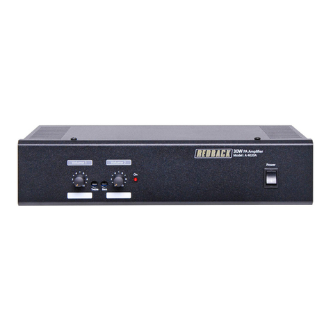
This manual suits for next models

1

Other Redback Amplifier manuals

Redback A 1922A User manual

Redback

Redback A 1922A User manual

Redback A 4312 User manual

Redback

Redback A 4312 User manual

Redback A 4017 User manual

Redback

Redback A 4017 User manual

Redback A 4905 User manual

Redback

Redback A 4905 User manual

Redback A 4037 User manual

Redback

Redback A 4037 User manual

Redback A 4031C User manual

Redback

Redback A 4031C User manual

Redback A 4377A User manual

Redback

Redback A 4377A User manual

Redback A 4310 User manual

Redback

Redback A 4310 User manual

Redback A 4931 User manual

Redback

Redback A 4931 User manual

Redback A 1937 User manual

Redback

Redback A 1937 User manual

Redback A 4116 User manual

Redback

Redback A 4116 User manual

Redback A 4387A User manual

Redback

Redback A 4387A User manual

Redback A 4020B User manual

Redback

Redback A 4020B User manual

Redback PHASE 5 A 4395A User manual

Redback

Redback PHASE 5 A 4395A User manual

Redback Phase 5 A 4390A User manual

Redback

Redback Phase 5 A 4390A User manual

Redback A 4235 User manual

Redback

Redback A 4235 User manual

Redback A 4270 User manual

Redback

Redback A 4270 User manual

Redback A 4205 User manual

Redback

Redback A 4205 User manual

Redback A 5122 User manual

Redback

Redback A 5122 User manual

Redback A 4230 User manual

Redback

Redback A 4230 User manual

Redback A 4377 User manual

Redback

Redback A 4377 User manual

Redback A 4370A User manual

Redback

Redback A 4370A User manual

Redback Phase 4 Installation guide

Redback

Redback Phase 4 Installation guide

Redback A 4860 User manual

Redback

Redback A 4860 User manual

Popular Amplifier manuals by other brands

Boss Audio Systems CHD4000 user manual

Boss Audio Systems

Boss Audio Systems CHD4000 user manual

Jadis JA30 owner's manual

Jadis

Jadis JA30 owner's manual

Sherwood AVP-9080 user guide

Sherwood

Sherwood AVP-9080 user guide

Rockville RPA-5 owner's manual

Rockville

Rockville RPA-5 owner's manual

Creek Audio EVOLUTION 100A instruction manual

Creek Audio

Creek Audio EVOLUTION 100A instruction manual

HearingAble IRIS20 user manual

HearingAble

HearingAble IRIS20 user manual

GRASS VALLEY 7510 instruction manual

GRASS VALLEY

GRASS VALLEY 7510 instruction manual

Bogen C10 Technical specifications

Bogen

Bogen C10 Technical specifications

ADC RF Worx RDS-2 user manual

ADC

ADC RF Worx RDS-2 user manual

Rotel RB-870BX owner's manual

Rotel

Rotel RB-870BX owner's manual

JLM TMP-8 user manual

JLM

JLM TMP-8 user manual

PSSO PRIME user manual

PSSO

PSSO PRIME user manual

Dynakit stereo 70 Instructions for assembly and operation

Dynakit

Dynakit stereo 70 Instructions for assembly and operation

Pepperl+Fuchs HiD2844 quick start guide

Pepperl+Fuchs

Pepperl+Fuchs HiD2844 quick start guide

Monacor SA-100 instruction manual

Monacor

Monacor SA-100 instruction manual

Esoteric AI-10 owner's manual

Esoteric

Esoteric AI-10 owner's manual

Macrom 1000 owner's manual

Macrom

Macrom 1000 owner's manual

Cisco Prisma II Installation and operation guide

Cisco

Cisco Prisma II Installation and operation guide

manuals.online logo
manuals.online logoBrands
  • About & Mission
  • Contact us
  • Privacy Policy
  • Terms and Conditions

Copyright 2025 Manuals.Online. All Rights Reserved.