RedEarth DropBear User manual

DropBear_UserManual
RE_PROD_0012 Version2 Page 1 of 22 Date Issue 28/07/2020
DropBear
Home Battery System – On and Off-grid
Selectronic-Fronius with Lithium Batteries
(Single Phase)
User Manual

DropBear_UserManual
RE_PROD_0012 Version2 Page 3 of 22 Date Issue 28/07/2020
Shutdown and Safety Procedures
WARNING: Working inside the DropBear system is restricted to qualified personnel.
Installers must be qualified electricians with CEC accreditation for Solar and Battery.
WARNING: Lithium Battery hazard
The DropBear must only be installed by suitably qualified personnel.
Many of the procedures covered in the INSTALLATION sections of this
manual have inherent risks. Whilst the DropBear is designed to be safe,
including residual current device and double insulated cables, the voltages
connected or generated by the equipment are hazardous and potentially
fatal.
It is the responsibility of the installer to ensure the installation and all the
wiring is carried out according to all safety standards that are applicable to
the installation. The wiring diagrams and installation instructions are given
as a guide only and compliance to appropriate standards is the responsibility
of the installer.
From 1st February 2020, Non-Selectronic Accredited Integrators can obtain
a 10 year SP PRO Warranty by adding a Select.Live with new SP PRO
installations.
In our efforts towards constant product enhancement, this document is subject
to change at any time. Please visit www.redearth.energy and download the
appropriate and latest version manual.

DropBear_UserManual
RE_PROD_0012 Version2 Page 4 of 22 Date Issue 28/07/2020
Your RedEarth DropBear is an AC coupled ready-to-run energy storage system for On or Off-Grid
applications. It comprises of a Fronius Primo Solar MPPT inverter, Selectronic SP Pro Battery
inverter, self-managed lithium batteries and is fully assembled and factory tested. It is ready to
connect a PV Solar array and generator with either auto or manual start.
The DropBear is designed to be installed indoors or outside in a shaded area against a wall, in a
protected environment. A changeover switch is included in case of system failure. In this case the
loads can then be run off a generator until the system is operational again.
RedEarth Energy can provide remote monitoring, technical support and service to ensure ongoing
operation of your DropBear. You can also access remote monitoring to view your consumption
online.
DropBear installations require the electrical connection of:
•The customers load – there are dedicated terminals inside the unit to connect to.
•Two arrays of PV solar panels which can be installed with different orientations.
•Generator - there are dedicated power, auto-start and battery charger terminals
inside the unit to connect to.
•Monitoring - The installer will need to connect the system to the internet via LAN
cable or 4G SIM-card. The details on how to set this up are explained in the
INSTALLATION - MONITORING section of the Installation manual.
Note: The DropBear is not
designed to act as a main switch
board for the premises, as it does
not include space for additional main
& customer circuit breakers or
RCDs. The MEN link and Earth
connection need to be placed at the
premises as required.
About DropBear

DropBear_UserManual
RE_PROD_0012 Version2 Page 5 of 22 Date Issue 28/07/2020
Overview
DropBear Weight: 205kg without any Lithium batteries (42kg per battery)
Dimensions: 200.5 H x 131.4 W x 65.6 D [cm]
DropBear Minimum Clearance
Dimensions: 210 cm H x 166.7 cm W x 117.4 cm D

DropBear_UserManual
RE_PROD_0012 Version2 Page 6 of 22 Date Issue 28/07/2020
The Inside
The DropBear has two separate areas, one for the batteries and the other for the switches,
electronic equipment. Each section has a key-lockable door.
The top enclosure contains the-electronic equipment, switches and AC connection terminals.
The “AC Breakers” window shown below contains all the AC protective and isolation points as well
as the changeover switch. Each device contains an identification labelled directly above it.
Overview

DropBear_UserManual
RE_PROD_0012 Version2 Page 7 of 22 Date Issue 28/07/2020
The bottom enclosure consists of a robust and perforated base to support full weight of the
batteries and front and rear rails to secure the batteries in place.
If purchased without the full capacity of twelve (12) self-managed batteries (PowerPlus Energy’s
ECO 4840), you may purchase additional batteries along with the appropriate battery cables from
RedEarth Energy Storage.
Overview

DropBear_UserManual
RE_PROD_0012 Version2 Page 8 of 22 Date Issue 28/07/2020
Attached to the top of this chamber there are two fully enclosed battery busbars with the correct
number of battery cables required.
The DropBear is tested and commissioned at RedEarth’s headquarters before shipping. All
parameters are pre-set for correct operation between the SP Pro inverter, the Fronius and the
battery bank.
Some parameters may need to be adjusted during installation (eg. Generator size, maintenance
run, etc). Please check DropBear Commissioning section in this manual as well as the Selectronic
Manual.
You can reach RedEarth Energy Storage Ltd
during business hours on
On 0487 002 451 for Technical Support or
Head Office on 1800 733 637 (+61 7 3279 6707).
Overview

DropBear_UserManual
RE_PROD_0012 Version2 Page 9 of 22 Date Issue 28/07/2020
Battery Inverter
The Selectronic SP Pro operates as an inverter as well as a charger, it will
charge the batteries by rectifying AC into DC power as well as invert the
batteries DC power into AC usable power.
With many operating modes, our most popular is the "Self-Use"
configuration. This setting defines the following priority:
Loads -> Battery -> Export
All the solar power produced will be prioritized to the loads, the excess will
be used to charge the battery and once the battery is full, the solar will be
exported to the grid or ramped down in a "off-grid" application.
NOTE: In the event of critically low battery charge (SOC), the inverter will use the
grid to support the loads until the solar power returns. In a "off-grid" application, the inverter will
auto-start the generator or flash an emergency light.
•The Inverter/Charger will control the various energy sources depending on the demand or
SOC of the battery.
•The Inverter/Charger efficiently manages and maintains the batteries.
•Our intelligent battery management system accurately records the battery state-of-charge
(SOC) ensuring efficient use of the batteries and helps extend service life.
•The LED's on the SP Pro indicate the health and operational status of your system. It is
important to be able to understand the key values displayed.
Solar Inverter
The MPPT solar inverter converts the solar arrays DC power into usable AC power. This will then
directly power your home appliances first, then charges the battery bank available for later use.
In an Off-grid situation, if the system has excess power available, the incoming
power from the solar MPPT must be scaled back. The solar MPPT inverter is
automatic and proportionally powered down as directed by the battery inverter.
This inverters performance can be monitored via the embedded display or the
on-line portal.
Internal Components

DropBear_UserManual
RE_PROD_0012 Version2 Page 10 of 22 Date Issue 28/07/2020
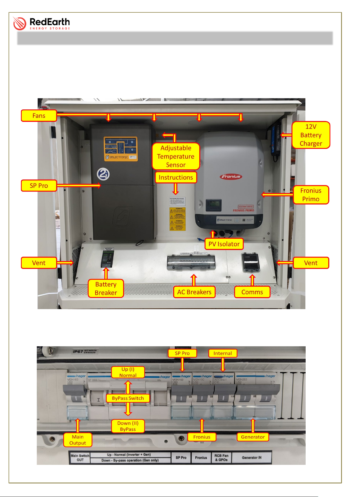
ByPass Feature
In the event of a system (battery or PV inverter) failure, the DropBear is fitted with a three-position
changeover switch that can operate as a ByPass, supplying power to the loads directly from the
generator (or grid).
The changeover switch has three positioning options,1, neutral and 2.
By pushing the switch up into position 1, it will operate in “Normal”
mode, meaning that the Battery and PV inverter are operating
together and using the generator/grid if available.
By pushing the switch down into position 2, it will operate in “ByPass”
mode, meaning that the power will bypass the inverters and “flow”
from the generator/grid directly to the loads.
The middle position is a neutral option. In this position all terminals
are disconnected, and no power will pass through it.
For more information, check “How to Operate” section in this manual.
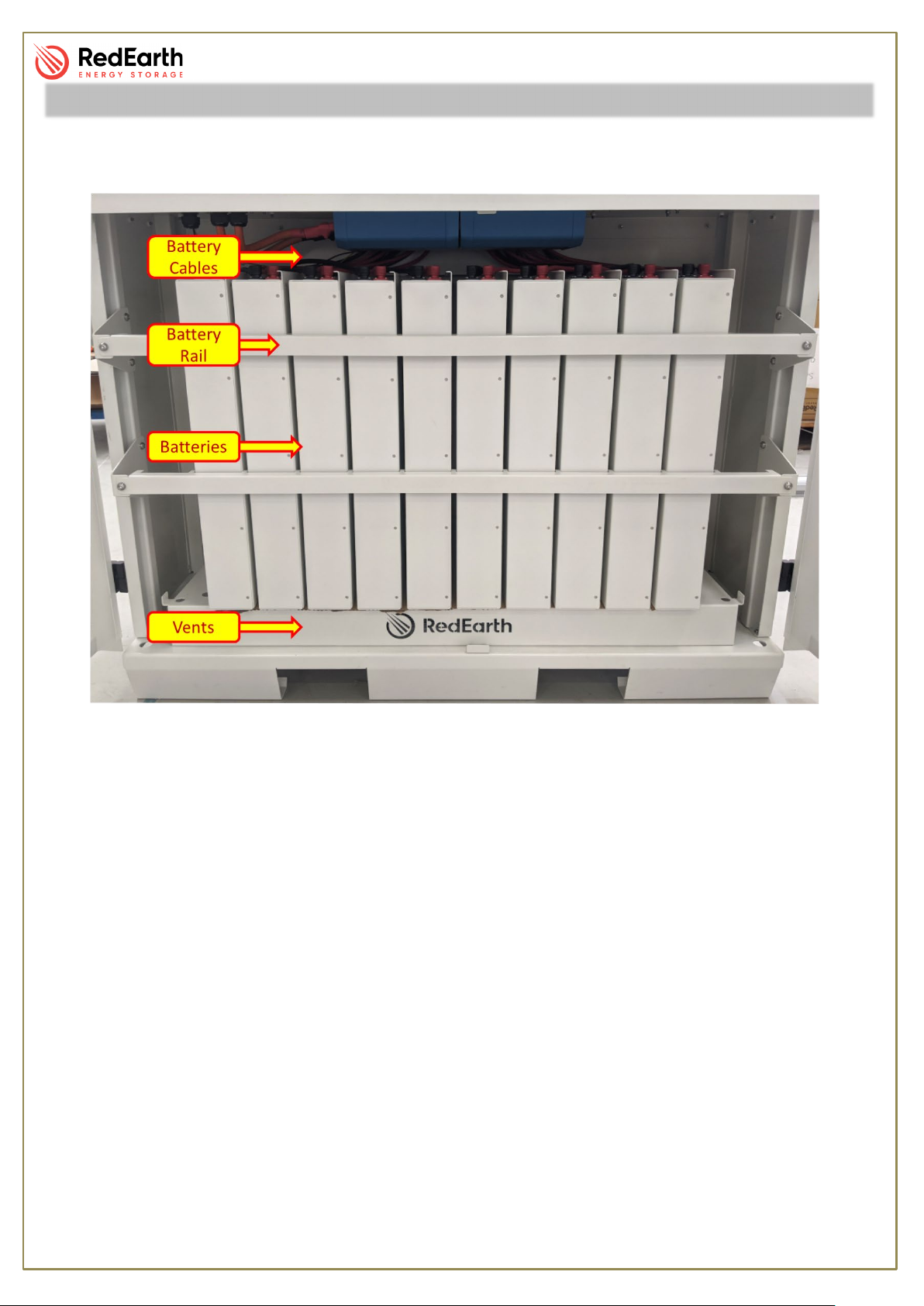
Battery
Batteries are a critical part of the Off-Grid system as they store energy
generated from the solar panels and fuel powered Generators. This power
can then be utilised at times when solar energy is not available.
The battery bank has been carefully sized to meet your requirements
according to your Load Profile and energy assessment. They do need
monitoring and maintenance to guarantee safe operation and service life.
The battery can be either a Self-managed lithium ECO from PowerPlus
Energy or LG Chem from LG.
12Volt battery Charger
The Blue Smart IP65 Charger is the new state-of-the art battery charger
from Victron with built-in Bluetooth offering long life durability, low
consumption and high performance.
This device is designed to keep your generator’s battery charged for the
event of an “auto-start” is requested, the generator has no issues with the
electric start.
Internal Components

DropBear_UserManual
RE_PROD_0012 Version2 Page 11 of 22 Date Issue 28/07/2020
Generator/Grid
Because the DropBear is an off or on grid system, it is possible to connect it to the grid, a
generator or both. These options must be specified upon purchase as the electrical design varies
with each option. However, retrofitting is also available.
If purchasing separately, inverter-generators are recommended for use with DropBear due to their
better power quality. If voltage, frequency or current waveforms of the generator are not of a high
enough quality, then it will be rejected by the inverter.
NOTE: Selectronic has the recommendation of a 9.5 kVA generator for the SPMC481 (5kW) and a
14kVA for the SPMC482 (7.5kW).
The following specifications must also be met for a guaranteed compatibility with the inverter.
-Generator waveform THD: < 10%.
-Generator Vrms range: 180 ~ 264Vac
-Generator voltage crest factor (Vpeak/Vrms): < 1.6
-Generator peak voltage: <380V
-Frequency range: 45Hz ~ 55Hz
-Frequency slew rate: <0.3Hz/sec
Generator Auto-Start
RedEarth’s DropBear is fitted with terminals that allow the connection of an auto-start generator.
The SP Pro is configured to start the generator when the batteries reach a State of Charge (SOC)
of 30% and stop when they reach a SOC of 40%. In the event that the generator does not turn on,
the batteries will discharge down to 20% and then the inverter will stop outputting power under
“LOW SOC fault”.
Low SOC Shutdown:
The SP Pro has a safety feature that determines a low battery cut-off. When this
level (low voltage) is reached, the inverter will turn off under “low battery fault”
and will need to be turned back on manually. See “How to Operate -> Restart”
section on how to bring the system back to operation
Internal Components

DropBear_UserManual
RE_PROD_0012 Version2 Page 12 of 22 Date Issue 28/07/2020
Temperature Sensor
A temperature activated relay is positioned on the rear panel behind the
top part of the Selectronic inverter as shown in the picture. This relay is
connected to the four (4) fans on the roof and will turn them on once the
set temperature is reached. The dial is set to activate between the
temperatures of 35⁰ and 40⁰ Celsius.
Internal Components

DropBear_UserManual
RE_PROD_0012 Version2 Page 13 of 22 Date Issue 28/07/2020
Power-up
To power-up the unit you must follow the steps below.
1. Turn on individual battery breakers.
This will charge up the capacitors inside the inverters. The LED on the three inverters will flash
and beep. Wait for approximately 10 seconds.
2. Turn on the Main Battery Breaker.
3. Turn on the PV isolator located under the Fronius Primo.
Before step 4, the inverters are powered but not turned on (outputting AC power).
4. Turn ON the Selectronic
To turn the inverter on you must press and hold the “ON” button on the top left-hand-side of the
Master inverter.
5. Turn on all AC circuit breakers.
Shutdown
The following shutdown procedure should be followed. This procedure is also displayed on a
sticker placed between the inverters.
How to Power-up / Shutdown my DropBear
NOTE: The Power-up and shutdown procedures are the same, only in
the reverse order.

DropBear_UserManual
RE_PROD_0012 Version2 Page 14 of 22 Date Issue 28/07/2020
Normal Operation
Normal operation assumes the SP Pro will use the Fronius (solar power) to charge the batteries
and supply the loads during the day, use the battery during the night and use the generator when
needed. When this type of operation is desired, this is what the AC breakers must look like after
performing Step 5 of Power-up Procedure (see How to Power-up/shutdown my DropBear).
ByPass Operation
In the event of maintenance or failure of the SP Pro and/or the Fronius and there is no power
output from the system, you can configure the system to operate in ByPass mode. This will allow
the generator to provide power directly to the loads.
To use this mode, the system must be set to the following configuration:
1. Turn OFF all the AC breakers.
2. Turn OFF Main Battery Breaker and individual battery breakers.
3. Turn changeover switch from position 1 to position 2.
4. Turn ON generator AC breaker and Main Switch Out.
5. Manually start generator.
By doing this, the generator will provide power directly to the loads.
How to Operate

DropBear_UserManual
RE_PROD_0012 Version2 Page 15 of 22 Date Issue 28/07/2020
Restart under low SOC
This procedure must be taken when the SP Pro has stopped inverting (providing 230V) but is still
turned on (has lights on the front display).
As mentioned previously in “Low SOC Shutdown”, when the SP Pro identifies the batteries at a
low SOC, it will stop producing 230V to avoid too deeply discharging the batteries and therefore
damaging them.
To restart the SP Pro, you must:
1. Turn OFF the Main Switch Out.
2. Press the ON button on the SP PRO (this will change the state of the inverter from “fault” to
“idle”).
3. Press the ON button once again (this will change the state of the inverter from “idle” to
“inverting”).
4. Wait for the Fronius to start producing power and charge the batteries to a safe level (at
least 3 lights on the battery gauge).
5. Turn ON the Main Switch Out.
How to Operate

DropBear_UserManual
RE_PROD_0012 Version2 Page 16 of 22 Date Issue 28/07/2020
Maintenance Schedule
Weekly
Check component operating lights are normal
Monthly
Clean inside the enclosure of dust, vermin or obstructions
Ensure safety labels/instructions remain visible
Clean air filter with vacuum or soft brush
Clean outside of enclosure soft brush or damp cloth
Bi-annually
Clean solar panel surfaces to ensure optimal performance.
Annually
Visually inspect for loose cables or connections near inverter
Clear any vegetation or overgrowth over the solar panels
Inspect conditions of solar panels, cables, array frame for damage or corrosion
End of Life Recycling
Please contact RedEarth Energy Storage to arrange recycling of your battery.
Maintenance and End of Life

DropBear_UserManual
RE_PROD_0012 Version2 Page 17 of 22 Date Issue 28/07/2020
The DropBear can be monitored online through the SwitchDin platform.
SwitchDin has developed a droplet (router) that enables the management and orchestration of
solar, battery storage and electrical loads to improve energy efficiency, reduce costs and
maximise benefits to the owner and the utility. This droplet can be found in the Comms area of the
DropBear (right of the AC breakers).
Monitoring
Registering
1. OPTIONAL: During testing and commissioning, RedEarth will setup an account for the end
user and send out the following invitation.
2. Click on the link to create an account.
3. In a web browser, visit https://app.switchdin.com/ and Sign in to view your system.
Monitor My DropBear
1. If you haven’t received this email from us, please email
support@redearth.atlassian.net with the following information:
Full name, address, unit serial number with subject: Setup online monitoring

DropBear_UserManual
RE_PROD_0012 Version2 Page 18 of 22 Date Issue 28/07/2020
How to monitor my system?
Once signed in, you will see the following page.
Overview Tab
LIVE DATA - Illustrates the movement of power at this given moment, in terms of PV production,
battery power, grid and load.
WEATHER - Displays the current weather at the location of the system, time of day when solar is
available, wind speed and humidity.
SYSTEM STATUS - Shows the last time data was collected from the SwtichDin droplet and
updated to this profile.
SOC - This graph shows the state of charge of the battery for today as a percentage value.
SO FAR TODAY – This section has three graphs. Two of these are doughnut graphs and relate to
Production (PV) and Consumption (Loads). The third graph shows power values from solar, load,
grid and battery over time.
Monitor My DropBear
Battery State of
Charge (SOC)
In this example, the solar PV is producing 22.94kW of power, there is 17.04kW of load and solar PV is exporting
5.9kW to the grid. The battery power is 0kW.
Power flow
between solar,
grid, load and
battery, in kW

DropBear_UserManual
RE_PROD_0012 Version2 Page 19 of 22 Date Issue 28/07/2020
Performance Tab
The performance tab can be customised to see several historical data about the system.
NOTE: If the “Grid Power” is a positive value (above the zero line) then the system is buys power
from the grid. If this is a negative value (below zero the line), then the system is selling power to
the grid.
NOTE:If the “Battery Power” is a positive value (above the zero line) then the in a charging state.
If this is a negative value (below zero the line), then it’s discharging.
Live Tab
The Live Tab displays all the live readings of data in numerical form from the connected devices.
In the example on the previous page, 123.61kWh energy was produced from solar. 21.09kWh of it was
exported to the grid and 102.52kWh was consumed by the loads and 0W was stored in the battery.
123.61kWh energy was produced from solar. 21.09kWh of it was exported to the grid and 102.52kWh
was consumed by the loads and 0W was stored in the battery.
Monitor My DropBear

DropBear_UserManual
RE_PROD_0012 Version2 Page 20 of 22 Date Issue 28/07/2020
Users Tab
This tab shows the users who can view this system. This will include you, the customer, and staff
involved in monitoring your system.
Alert Tab
The alert tab shows any errors or warnings received about the system. You will also receive an
email if an alert occurs.
Further Questions
For further questions, feel free to email us at support@redearth.atlassian.net
Monitor My DropBear
Other manuals for DropBear
2
Table of contents