iPower TPD-800A User manual

iPOWER TPD-800A User Manual
1
iPOWER TPD-800A
User Manual

iPOWER TPD-800A User Manual
2
Contents
Ⅰ. TPD-800A Introduction................................................................................................................................3
Ⅱ. Function Description ....................................................................................................................................3
Ⅲ. Applied Range ..............................................................................................................................................3
Ⅳ. Product Picture & Description......................................................................................................................4
Ⅴ. Mounting Method.........................................................................................................................................5
Ⅵ. Hardware Introduction..................................................................................................................................5
1. Powering on & Self-check........................................................................................................................5
2. Current, Temperature & Humidity Monitoring.........................................................................................5
3. Water logging & Smoke Monitoring ........................................................................................................5
4. Outlet Fault Monitoring............................................................................................................................5
5. Individual Current, Total Current, Temperature & Humidity Over Limit Monitoring…………………..5
6. Self-checking Parameter Monitoring........................................................................................................5
7. Stopping Alarm Monitoring......................................................................................................................5
8. Master / Slave TPD-800A Configuration .................................................................................................6
9. Daisy-chain Connection Method ..............................................................................................................6
10. Radialized Connection Method ..............................................................................................................6
11. Software Upgrade in Hardware...............................................................................................................7
Ⅶ. Software Introduction...................................................................................................................................8
1. Software Overview ……………………..………………………………………………………..… ...…8
2. Access Method..................……………………………………………………………………...…....8
3. Device Daisy-chain.…………………………………………… ………………………….…….....24
4. Frequently Asked Questions..………………………………….……………………….…..…….....25

iPOWER TPD-800A User Manual
3
Ⅰ. TPD-800A Introduction
TPD-800A can monitor, control and manage the power supply of many equipments in cabinets in data room all
over the world through LAN or WAN. For meeting with the restrictions and requirements in different
environment, TPD-800A supplies many connection methods; can be connected through RJ-45 in the LAN and
WAN; can be accessed and controlled through standard network management station.
Ⅱ. Function Description
1. Monitoring function: by the cooperation of LED screen and knob on TPD-800A, user can monitor the total
load current, voltage, individual load current, power on/off state of individual outlet, temperature/humidity,
smoke, water logging, door opening/closing state. User can also monitor through LAN or WAN.
2. Controlling function (May not support this version): turn on/off individual outlet, set the interval of sequential
power on/off, set the time for outlet power on/off.
3. Keeping the original state (May not support this version): keep the original state of each outlet when resetting.
4. User-defined alarming: the limit of total load current, individual load current (May not support this version)
and temperature/humidity.
5. System default alarming: system alarming when total load current, individual load current beyond the limit
(May not support this version), individual outlet breaks down, smoke appears, water logging or door opening.
6. Alarming methods: problem information show on LED screen and TPD-800A buzzer alarms, the problem
value flashes on web interface and PC buzzer alarms, automatically send e-mail to system administrator,
SNMP sends alarm information, wireless telecommunication report to administrator.
7. KwH measurement: measure the total Kilowatt per hour
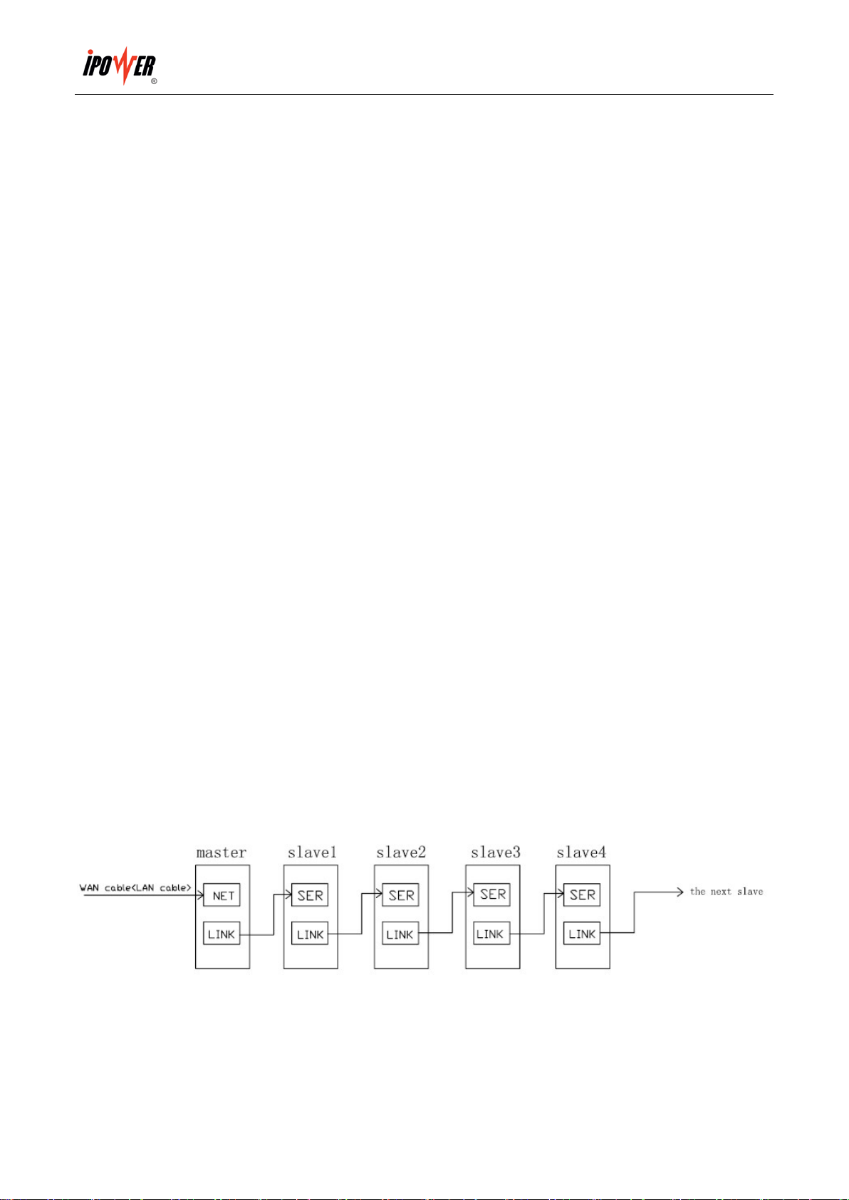
8. Daisy-chain: can daisy-chain at most 9 pcs TPD-800A.
9. Alarming record: record and save the alarming information which can be checked and exported. (Note: record
can only be checked in order. Record information concludes overload, temperature/humidity beyond the limit,
smoke appears, water logging, door opening/closing, outlet breaks down and the insert and pull out of the
sensors)
10. User management: User right configuration
11. Safe mode turn-off: remote soft turn off the TPD-800A
12. Access method: Web, through IE, SNMP (V1/V2/V3) or Telnet, SSH to access and control.
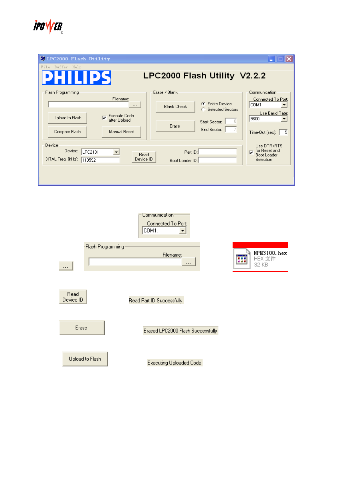
13. Support multi-user operation system and software upgrade.

iPOWER TPD-800A User Manual
4
Ⅲ. Applied Range
1. TPD-800A can be applied to server cabinet, network cabinet etc.
2. The socket quantity (8 or 12) and socket standard (C13, C19, NEMA5-15R, NEMA5-20R) of TPD-800A can
be selected.
3. TPD-800A conforms to RoHS instruction, suitable for 110VAC and 220VAC power supply, can meet the
customers’different requirements all over the world.
Ⅳ. Product Picture & Description
1: Port1:The software upgrade port of hardware
2. LINK: when daisy-chain TPD-800A, connect with the SER port of the next TPD-800A
3. SER: for daisy-chain
4. NET: 10-100Mbps Ethernet(RJ-45 Connector), to connect PC, Hub, router or switch.
5. No.2: select outlet
6. RESET: set master or slave TPD-800A and reset TPD-800A (press 30 seconds)
7. Mounting bracket

iPOWER TPD-800A User Manual
5
8/9. Display TPD-800A address and other parameters
10. RUN:operation indicator
11. M/S:Master/slave indicator
12. OUTLET No. 1:select outlet and other parameters (T/H)
13. Water: connect water sensor
14. Smoke: connect smoke sensor
15/16. T/H1, T/H2: connect temperature/humidity sensor
17. Fuse
18. Power indicator
19. Socket lock
20. Outlet sockets
Ⅴ. Mounting Method
Horizontal installation.
Ⅵ. H ar d w ar e I n tr od u cti on
1. Power on & Self-check
The buzzer makes a sound when TPD-800A is connected with AC power source, LED screen lightening and
sequentially display 8.8.8. 8.8.8. (it means digitron is normal, any different display means fault), software
version number (for example U0.0 1.01), baud rate (for example9 600), TPD-800A default address (For
example ABC DEF), TPD-800A series (for example310 1-d), socket quantity(for example OU7 08), finally
display the value of which OUTLET No.1 pointing to (for example A1 0.0), and RUN indicator flashes. M/S
indicator on means this TPD-800A is master while off means slave TPD-800A.
2. Current, voltage, temperature & humidity Monitoring
OUTLET No.1 and OUTLET No.2 are together used to monitor the relative outlet value (OUTLET No.2 has the
function of plus 8 port or minus 8 port).
3. Water logging & Smoke Monitoring
3.1 When the water logging sensor monitoring the water, TPD-800A LED screen displays and the buzzer
alarms at the same time.
3.2 When the smoke sensor monitoring the smoke, TPD-800A LED screen displays ,and the buzzer
alarms at the same time.
4. Outlet Fault Monitoring
When one outlet breaks down (For example: A1), the TPD-800A LED screen will display relative fault (for

iPOWER TPD-800A User Manual
6
example: A1 Err), and the buzzer alarms at the same time.
5. Individual current, total current, voltage, temperature & humidity over the Limit monitoring
5.1 When individual load current, total load current, voltage, temperature & humidity value are lower than the
Min., the TPD-800A screen displays as A.1 (that means the load current of outlet No. 1 is lower than the Min.
value)
5.2 When individual load current, total load current, voltage, temperature & humidity value are higher than the
Max., the TPD-800A screen displays as A.1.. (that means the load current of outlet No.1 is higher than the Max.
value)
6. Self-checking Parameter Monitoring
Make the OUTLET N0.1 display - - - - - -, then press reset button, the TPD-800A LED screen sequentially
display the TPD-800A self-checking parameter for one minute.
7. Stopping alarming
Click the RESET button to stop alarming for one minute (When TPD-800A has alarm information, OUTLET
No.1 has no function, you have to stop the alarming for one minute then you can check other information. But it
will continue alarming after one minute until you have modified the fault.)
8. Master / Slave TPD-800A Configuration
Press the RESET button for 12 seconds(the interval of RUN light is 2 seconds), the indicator of M/S on indicates
the TPD-800A is the master TPD-800A; Press the RESET button for 6 seconds(the interval of RUN light is 2
seconds), the indicator of M/S off indicates the TPD-800A is the slave TPD-800A. Account the time please refer
to the RUN indicator (T= 2S)
9. Daisy-chain Connection Method
9.1 Each TPD-800A owns the sole default address which is different from others. The address has been locked
before leaving factory and can not be changed.
9.2 Set one TPD-800A as master and the others as slaves. One master can daisy-chain 9pcs TPD-800A slave at
most.
9.3 One end of the network wire connects to the LINK port of the master TPD-800A, the other end connects to

iPOWER TPD-800A User Manual
7
the SER port of the first slave TPD-800A, then use one end of another wire connects to the LINK port of the first
slave TPD-800A, the other end connects to the SER port of the next slave TPD-800A. Use the same way to
connect other slave TPD-800A.
9.4 One end of the network wire connects to the net port of the PC; the other end connects to the NET port of the
TPD-800A, then through IE to access. (Details please refers to the software introduction)
10. Radicalized Connection Method
10.1 Set one TPD-800A as master and the others as slaves. One master can link 9pcs TPD-800A slave at most
10.2 One end of the network wire connects to the net port of the PC; the other end connects to the NET port of
the TPD-800A
10.3 One end of the network wire connects to the LINK port of the master TPD-800A, the other end connects to
the RJ-45 port of the HUB (special HUB for TPD-800A link from our company)
10.4 Use the end of another network wire connects to another in/out port of the HUB, the other end connects to
the SER port of the slave. Each in/out port of HUB connects to the SER port of one slave TPD-800A, can link
9pcs slave at most.
10.5 Through IE to access (Details please refers to the software introduction)
11. Software Upgrade in Hardware
11.1Our company will provide the file of software upgrade ,please save it in your PC
11.2 Please open the software upgrade file ,then double click this file to install
the software.

iPOWER TPD-800A User Manual
8
11.3 Operate this software after installation, see the following picture:
11.4 The RJ-45 end of the signal wire for upgrade software (special wire, it must from our company) inserts to
PORT1 on TPD-800A, DB9 end inserts to the RS-232 port of PC
11.5 Please select the correct series port in , make other selection according the picture
11.6 Click in , add the file .
11.7 Power on the TPD-800A
11.8 Click , it will show when read successfully; if fails, please check the
connection wire and the communication port
11.9 Click , it will show when erase succeeds; If fails, please
check the connection wire and the communication port
11.10 Click , it will show when uploading the file succeeds; if fails,
please check the connection wire and the communication port
11.11 Power off the TPD-800A
11.12 Power on the TPD-800A, LED screen will show the new version which means the software upgrade
successful and then it can work normally.

iPOWER TPD-800A User Manual
9
Ⅶ. Software Introduction
1. Software overview
This software is a technology that employs the total embedded system solution. It is based on the monitoring
technology of SNMP standard protocols,encryption of SSH data transmission, sensor network node technology and
other high-tech technologies. Through the network the user can timely monitor and remotely control the devices
power and micro environment in the cabinet. It help user to monitor、control and manage the status of each outlet as
well as the sensor of environment temperature, humidity, smoke, water, door open status with its multiple-user
operation system、friendly administration interface and compatible network connection.
2. Access Method
By connecting the devices to the LAN or WAN, the user can carry out the remotely control and management
through IE browser、SNMP、SSH and Telnet.
2.1. IE Access
Open the IE browser (only support IE6.0 and IE7.0 version currently), input the device IP address and log on to the
administration interface with the correct user name and password, The system will automatically log out if the user
input the incorrect user name or password for three times consecutively.
The administration interface is made up of three parts: the system information interface、user guide menu and the
device control interface.
The system information interface: mainly contain the company Logo as well as the device current IP address;
User guide menu: display the user name and function menu, it helps and guides the user complete the operation
conveniently and promptly;
Device control interface: the user can monitor、control and manage the devices through the device control interface.,
please see the details as below 1)to 16):
1) Device Control
"Device Control" interface control the switch on/off of the each outlet and look over the status of outlets and basic
information of sensors, details as below:
a) to view the model of device;
b) "output Name" display the name of each outlet;
c) "current" display the total load current as well as the current of individual outlet. The digit of current in red will
flash when it's over the limiting value to alarm
d) "Output Status" shows the switch on/off status of outlets: means on, means off, means problem
occurred to the outlet;

iPOWER TPD-800A User Manual
10
e) "Control" controls the switch on/off: "ON" means switch on, "OFF" means switch off, "REBOOT" means
restarting the device and its default status was "NONE", the user can switch on/off single outlet, multiple-outlet
or all outlets;
f) The load current can be read if the device equipped with ampere meter. If not, it will display" Not found"
g) The power consumption can be read if the device equipped with power consumption meter. If not, it will display
"Not found"
h) The corresponding value and status of temperature, humidity, smoke, water logging and door open can be read if
all this sensors are equipped. If not, it will display "Not found". The digit in red will flash if the sensors alarm.
2) Sensor Status
View the current status of all these sensors. Details as below:
a) "Temperature/Humidity" displays the current temperature/humidity sensor connection status and value. "Not
found" means no Temperature/Humidity sensor is connected. The digital figures in red will flash if it's over the
value to alarm.
b) "Door" displays the connection status of door. "Not found" means no door sensors are connected. The word
"open" in red on the screen will flash if the door is opened.
c) "Smoke alarm" displays the connection of smoke sensor, "Not found" means no smoke alarm is connected. The
word "CLOSE" or "OPEN" can be read on the screen if connected. The word "YES" in red will flash if smoke
alarm happens.
d) "Water logging" displays the status of water sensor, "Not found" means no water sensors is connected. The word
"YES" or "NO" can be read when connected. The word "YES" in red will flash if water-logging alarm happens.
3) Device Configuration
Configure the device series number, input outlet name as well as the interval of sequential power on/off, details as
below:
a) " TPD-800A Address No": each device has a unique series number; the user can not normally monitor and
manage the device if the displayed figure is not the same as the device series number.
b) " TPD-800A name": configure the device name which can reach as long as 20 bytes;
c) Configure outlet name, it can reach as long as 35 bytes;
d) "Sequence Interval": configure it according to specific requirement; the interval is between 0 to 255 seconds.
4) Network
Configure IP address、Sub-net Mask、default gateway DNS according to different application environment, details
as below:

iPOWER TPD-800A User Manual
11
a) IP address: LAN or WAN IP address, the default IP is 192.168.1.163
b) Sub-net Mask: correspond with IP; the default sub-net mask is 255.255.255.0
c) Gateway: correspond with IP; the default gateway is 192.168.1.1;
d) DNS address: the default DNS is 0.0.0.0, any DNS address of normal domain name resolution, make sure the
e-mail can be send successfully
Note: network configuration information will be valid after system reboot.
5) Timing Control
Configure the time of power on/off, the device automatically switch on/off according to the set time, details as
below:
a) Click on “Setting" to adjust time and make sure the time is the same with the PC
b) "ON Timing" time of power on setting, the format is: yy/mm/dd hours: minutes:
"OFF Timing" time of power off setting, the format is: yy/mm/dd hours: minutes:
c) Select "Repeat", the device will automatically power on/off daily according to the time set by user if setting
success.
6) Threshold Value
Set current, temperature/humidity threshold and ensure the devices operation well in normal status, details as
below:
a) Individual outlet current rate: 0~10(A), total current rate: 0~16(A) or 0~32(A), connecting to the load, the device
will alarm when the current exceed the set limiting value of current.
b) Temperature rate setting: -40~215(℃), Humidity rate: 0~100(100%), the sensor will alarm when the
temperature/humidity exceed the limiting value.
Note: the Max. value can not be smaller then the Min. value.
7)Alarm Setting
Set the style of alarm, voice alarm and e-mail alarm. The alarm information will be sent to the administrator by
voice or e-mail when the current, temperature/humidity exceed the limiting value or any problem occurred.
a) Voice alarm:
♦Select the voice document from the PC through the interface prompt, save it after testing;
♦The interface displays the path of the voice document and prompt of setting success;
♦The PC will alarm through the voice set by user when device alarms, only single user setting is available to the
voice path and only one voice path can be saved.
Note: The voice alarm count on the browser, the voice alarm can not be realized when the browser is closed

iPOWER TPD-800A User Manual
12
b) E-mail alarm:
♦Select “Enable e-mail alarm"
♦POP3 address: receive e-mail server address, e.g. Sina POP3 address: pop.sina.com;
♦SMTP address: deliver e-mail server address, e.g.Sina SMTP address: smtp.sina.com;
♦Port: delivery e-mail port (general e-mail port: 25), input the corresponding output port according to e-mail level.
♦User name: input the receive e-mail address, make sure this e-mail address is accordant with the SMTP address
♦User Password: fill in the e-mail password of sender, the password is accordant with e-mail of sender.
♦Authentication type: the way of e-mail login (general e-mail default as: LOGIN), select the login way according to
the level of e-mail
♦To address: the e-mail address of receiver, the user can fill one or more receiver, but all the receive address must
be separated by ";"
♦Cc to: fill in one or more CC-email address, each address must be separated by ";"
♦From address: the same with User name
♦Repeat interval: interval of email sending
Note: Please fill in correct DNS on “Network Config” interface.
E-mail alarm function only support non-encrypted e-mail, does not support encrypted e-mail.
8)Alarm Logs
Automatically record the alarm information and data, offer viewing and leading out function, details as below:
a) Daily record the alarm and recovering information of current overload, temperature/humidity from exceeding
limitation, problem occurrence and the status information of sensor connection and disconnection;
b) "Select Device" to select and view the single device daily record information;
c) Select "First", "Previous" "Next" to view the daily record;
d) Select "WEB" or "EXCEL" to leading-out the daily record information;
e) "clear all records" to clear all the record information of single device.
9) System
a) View the latest software version, time of update, hardware address( MAC), RAM space, CPU occupancy rate
and total system operation time.
b) Click "reset system settings" to restore factory settings e.g. Device Configuration, Alarm Setting, Web, Console,
SNMP, User Manage and other configuration of menu; it will be valid after rebooting.
10) Web
Configure HTTP, user can enable or disable the HTTP port, details as below:

iPOWER TPD-800A User Manual
13
♦Set and save the HTTP port according to the network environment, the default HTTP port is 80;
♦Select "Enable" to start and save HTTP, set the HTTP enable and can not be closed
Note: the setting will be valid after system reboot.
11) Console
Configure devices Telnet and SSH access method, details as below:
a) Telnet
♦Select "Enabled" or "Disabled" to decide start the Telnet function or not, the system defaults status was "Enabled"
♦Change the Telnet port according to requirement of user, the default port was: 23
b) SSH
♦Select "Enabled" or "Disabled" to decide start SSH function or not, the system default status is "Disabled"
Note: the changed Console configuration will be valid after reboot
12) SNMP
"SNMP" interface configure the SNMP access method, details as below:
a) Select "Enabled" or "Disabled" to decide starting the SNMP function or not through drop-down menu of "SNMP
Agent" interface;
b) Set the character string of "get" "set" "trap" respectively. Get community is to offer read-only channel mark of
visiting the MIB object, set community is to offer the read-write channel mark of visiting MIB object, TRAP
community is the style mark of all TRAP information generated and sent. The default status of these three items is:
public, private, private. The length of the community string must be between 1-24 bytes.
c) Set calculagraph of SNMP trap from 1 to 65535 seconds, better to above 10 seconds, the defaults time is 30
seconds.
d) Set trap destination, input the SNMP management platform object address in the frame of Trap Destination, the
Trap information will be sent to the corresponding address automatically, user can set 2 Trap Destinations.
e) The system name of SNMP records the information of SNMP system name.
f) SNMP server position record the server position information
Note: the SNMP configuration will be valid after reboot
13) Update
To upgrade the software, the image.bin file packet from supplier is required when upgrading, the user can complete
the updating process according to the prompt message, details as below:
a) Connecting device and the PC directly by network cable.
b) Click "Browse" and select the the image.bin file path on the PC

iPOWER TPD-800A User Manual
14
c) Click "Update"
d) Return to prompt information automatically when file submitting successfully (letters in blue), which means the
update document submitted successfully.
e) Waiting for the system pop the login window after software system initialized when file submit successfully.
Note: Make sure no power failure, no network disconnected and no operation on the interface when upgrading
14) User manage
Create or delete user account and configure user's right, details as below:
a) The administrator can add 5 users at most. The user name can only be made up of letters, number and underline;
other character can not be filled in.
b) Administrator can open the "Edit" which under the Action menu to modify the password and lever of all the
users.
c)Administrator can delete users, but the last administrator can not be deleted.
d) Administrator can open the "Edit" which under the "Control Rights" menu to view and assign the user's right, the
administrator holds all the right.
Note: General user can only monitor and manage the assigned devices status, sensor status, device configuration
information, network configuration, power on/off automatically, limiting value to alarm setting, alarm setting, daily
record information and so on.
15) Restart
"Restart" interface is designed to restart and refresh the device software system (e.g. Change the IP address, HTTP
port, Telnet port, software update), no need to cut off the power supply as this operation does not affect the normal
power supply. The system will automatically pop the login window when system restart.
16) Logout
According to the prompt message to close the software system interface`
2.2.SNMPAccess Method
SNMP(Simple Network Management Protocol), this software support the V2 version of SNMP with a MIB file
which contain an enterprise number, network management system offer network management of device through
SNMP, the user can change the output port name, view the device and sensor status, receive alarm information
through SNMP approach.
The user has to open the SNMP access method through visiting interface of IE browser, please refer to the 13th item
of IE access method SNMP introduction. Install corresponding SNMP management software after completing the
SNMP start setting, set up the configuration according to the software menu provided by SNMP software company,

iPOWER TPD-800A User Manual
15
leading-in MIB file on the SNMP management platform, user can monitor and manage the device status
information and alarm Trap information after translating and editing success, the details information of device
status are as detailed in figure 2-1, figure 2-2,
1). The status of the device and sensor can be read through the table format of SNMP software, details as below:
Figure 2-1 the information table of device output status
Figure 2-2 the information table of device sensor status
Menu Description of menu
Device name Display the connected device name
Device Type Display the connected device model
Series No Display the current hardware device series number
ON Interval The interval of power on
Total Load Value Display the total output load current
Temperature 1 Display the current connection status and temperature of temperature sensor 1
Humidity 1 Display the current connection status and humidity of humidity sensor 1
Temperature 2 Display the current connection status and temperature of temperature sensor 2
Humidity 2 Display the current connection status and humidity of humidity sensor 2
Temperature 3 Display the current connection status and temperature of temperature sensor 3
Humidity 3 Display the current connection status and humidity of humidity sensor 3
Door 1 Display the current status of door sensor 1
Door 2 Display the current status of door sensor 2
Smoke Display the current status of smoke sensor
Water Logging Display the current status of waterlogging sensor
Menu Description of menu
XX output ID XX stands for device name, output ID display the device ID address
Name The output end name
Status The corresponding switch on/off status of each output
Load Value The corresponding current of each output
Load Low limit The corresponding minimum value of each output
Load High limit The corresponding maximum value of each output

iPOWER TPD-800A User Manual
16
2) According to the setting of the SNMP on the IE browser interface, TRAP information will be sent to Trap
Destination automatically, the time information of alarm, device name and the alarm type will be included in the
TRAP information. Overview of the TRAP information as below:
Minor 11/17/2009 11:07:56 device
thresholdAlert
[1] unitName.0 (DisplayString): total load
[2] deviceName.0 (DisplayString): device1
[3] alertStatus.0 (DisplayString): load low
[4] alertValue.0 (DisplayString): 7.2
[5] lowLimit.0 (DisplayString): 10.0
[6] highLimit.0 (DisplayString): 16.0
[7] pollLastState (Integer): unk
2.3. SSH command line console access
SSH(Secure Shell) is kind of protocol which provide telnet and other secure network service through unsafe
network. Besides the configuration of safe network terminal conversation and power management, SSH
conversation can also be employed to safe direct connecting devices.
The configuration and client of SSH require using the PC client agent, lots of free shared software like PUTTY are
available or user can buy the SSH client in the market.
The SSH monitor, control and manage the device mainly through command line like STATUS ON OFF、REBOOT、
SHOW、SET、ADD、REMOVE、RESET、RESTART、QUIT
1). STATUS
"STATUS" command line can be used to view the basic information of devices, status of total output, individual
output and sensor; the format of command line: STATU【ADDRESS】【 OPTION】
【ADDRESS】: the series number of connected device, view the current status of device according to the series
number;
【OPTION】: View the device information according to the options, as detailed in Figure 3-1
Figure 3-1 the description table of STATUS OPTION
【OPTION】Description
SUMMARY View the basic information of device, e.g device series, model, series number,
output quantity, total load current, total voltage, and power consumption
OUTPUTS View all the output numbers, switch on/off status, threshold of individual and total

iPOWER TPD-800A User Manual
17
current
NO. This option only require outlet No., user can only view one outlets status at a time,
e.g output name, switch on/off status, load current, and the current threshold.
SENSORS View the sensor status, e.g the current status of the temperature/humidity/door
/water/smoke sensors and the threshold of temperature/humidity.
For instance: STATUS ABCDEF 5: View the status of output 5 of the TPD-800A whose series number is ABCEDF,
e.g the statue of switch on/off, load current and threshold of current.
2) ON
"ON" command can switch on the individual or total outputs.
Command input format: ON 【ADDRESS】【 OPTION】
【ADDRESS】: the series number of connected device, control the status of switch on/off according to the series
number.
【OPTION】select the quantity of the output to be controlled according to the options, as detailed in figure 3-2:
Figure 3-2 the description table of switch on option
For instance: ON ABCEDF 1: Switch on the output 1 of TPD-800A whose series number is ABCDEF
3) OFF
"OFF" command line can switch off individual or total output;
Command input format: OFF【ADDRESS】【 OPTION】;
【ADDRESS】: the series number of connect device, control the status of switch on/off according to this series
number
【OPTION】: select the output No. to be controlled according to the options, as detailed in figure 3-3:
Figure 3-3 the description table of switch off option
For instance: OFFABCDEF 1: Switch off the output 1 of TPD-800A whose series number is ABCDEF
4) REBOOT
【OPTION】Description
ALL Switch on all output of the device
NO. This option only require output number, switch on only one outlet at a time
【OPTION】Description
ALL Switch off all the output of the device
NO. This option only require output number, switch off only one outlet at a time

iPOWER TPD-800A User Manual
18
"REBOOT" command line can restart the individual or total outputs.
Command line input format: REBOOT【ADDRESS】【 OPTION】;
【ADDRESS】: the series number of connect device, control the status of switch on/off according to this series
number
【OPTION】: select the output No. to be controlled according to the options, as detailed in figure 3-4:
Figure 3-4 the description table of REBOOT OPTION
For instance: REBOOT ABCDEF 1: restart the output 1 of TPD-800A whose series number is ABCDEF
5) SHOW
"SHOW" command line can be used to read the network configuration information, system information, user
management information, e-mail configuration information, SNMP configuration information, HTTP configuration
information, TELNET configuration information, SSH configuration information, device configuration information,
output configuration information, timing power on/off configuration information, interval of sequential power on
configuration information and so on.
Command line input format: SHOW 【OPTION】;
【OPTION】as detailed in figure 3-5
Figure 3-5 the description table of SHOW OPTION
【OPTION】Description
USERS View the user name and level
DEVICE View all the connected devices and corresponding serial number
SYSTEM View the system information e.g software version, update time, MAC
code, CPU occupancy rate, operation time
NETWORK View the network configuration e.g IP address, sub-net mask, default
gateway, main DNS and back up DNS
SNMP View the SNMP configuration information
SSH View the SSH on/off status and port configuration
TELNET View the TELNET on/off status and port configuration
HTTP View the HTTP on/off status and port configuration
【OPTION】Description
ALL Restart all the output of devices
NO. This option only require output number, restart only one outlet at a time

iPOWER TPD-800A User Manual
19
MAIL
View the e-mail alarm setting, e.g POP3 server address, SMTP server
address, e-mail sending port, e-
mail sender's address and password,
receive address, carbon copy address, interval of alarm
ONINTERVAL
【ADDRESS】View the power on interval of this 【ADDRESS】
OUTPUTS
【ADDRESS】View the output name and address information of this 【ADDRESS】
TIMING
【ADDRESS】
ALL
View time setting and time of power on/off of all output of this
【ADDRESS】
NO.
View time setting and time of power on/off of this individual output of
this 【ADDRESS】
, "NO" means outlet number, input one outlet
number at a time.
For instance: SHOW USER: view user information and level.
6) SET
"SET" command line can configure and control the IP, SUBNET, GATEWAY, DNS1, DNS2, HTTP, TELNET, SSH,
SNMP, MAIL, THRESHOLD, TIMIGN, ONNTERVAL of the device.
A. Network configuration
Network configuration include: IP address, Sub-net mask, Gateway, DNS1 and DNS2
Command line input format: SET 【Network configuration】=
For instance: SEG IP=192.168.1.163: configuration network IP address: 192.168.1.163
Note: the network configuration will be valid after reboot.
B. HTTP
Command line input format: SET HTTP 【OPTION】
【OPTION】as detailed in figure 3-6-b
Figure 3-6-b the description table of HTTP OPTION
For instance: SET HTTP ENABLE: enable HTTP function
【OPTION】Description
ENABLE Set the HTTP enable
DISABLE Set the HTTP disable
PORT Set the HTTP port

iPOWER TPD-800A User Manual
20
Note: HTTP configuration will be valid after reboot
C. TELNET
Command line input format: Set TELNET 【OPTION】
【OPTION】as detailed in figure 3-6-c
Figure 3-6-c the description table of TELNET OPTION
【OPTION】Description
ENABLE Set the HTTP enable
DISABLE Set the HTTP disable
PORT Set the HTTP port
For instance: SET TELNET ENABLE: enable TELNET function
Note: TELNET setting will be valid after reboot
D. SSH
Command line input format: SET SSH 【OPTION】
【OPTION】as detailed in figure 3-6-d
Figure 3-6-d the description table of SSH OPTION
For instance: SET SSH ENABLE: set the SSH enable
Note: SSH setting will be valid after reboot
E. SNMP
Command line input format: SET SNMP 【OPTION】
【OPTION】detail as figure 3-6-e
Figure 3-6-e the description table of SNMP OPTON
【OPTION】Description
ENABLE Set the SNMP enable
DISABLE Set the SNMP disable
GETC Set getting the character string of community
【OPTION】Description
ENABLE Set the HTTP enable
DISABLE Set the HTTP disable
PORT Set the HTTP port
Other manuals for TPD-800A
1
Table of contents
Other iPower Power Supply manuals