Triamec TP150 User manual

TP150/TP350 Power Supplies
Hardware Manual
Document HWTP150-TP350_B_HardwareManual_EP
Version 017
Source :\doc\Hardware\HWTP\HWTP150-TP350_B_HardwareManual\
Destination T:\doc\Hardware\
Owner mvx
Copyright © 2014
Triamec Motion AG
All rights reserved.
Triamec Motion AG
Industriestrasse 49
6300 Zug / Switzerland
Phone +41 41 747 4040
Email inf[email protected]
Web www.triamec.com
Disclaimer
This document is delivered subject to the following conditions and restrictions:
This document contains proprietary information belonging to Triamec Motion AG. Such information
is supplied solely for the purpose of assisting users of Triamec products.
The text and graphics included in this manual are for the purpose of illustration and reference only.
The specifications on which they are based are subject to change without notice.
Information in this document is subject to change without notice.
2014-04-01

Table of Contents
1 Safety Information...................................................................................................................................3
2 Product Description.................................................................................................................................4
2.1 Block Diagram..................................................................................................................................5
3 Technical Specifications...........................................................................................................................6
3.1 Environmental conditions................................................................................................................6
3.2 Electrical Specifications....................................................................................................................7
3.3 AC-Line.............................................................................................................................................8
3.4 Discharge Currents...........................................................................................................................8
3.5 EN 61800-5-1...................................................................................................................................8
3.6 EN 61800-3.......................................................................................................................................8
3.7 Overvoltage......................................................................................................................................9
Internal brake capability 9
External brake resistor 9
Overvoltage protection 9
3.8 LED Diagnostics and Status............................................................................................................10
3.9 RS232 communication...................................................................................................................10
4 Mounting and Wiring............................................................................................................................11
4.1 Dimensions....................................................................................................................................11
4.2 Cooling...........................................................................................................................................11
4.3 Brake resistor.................................................................................................................................11
4.4 Capacitor reforming.......................................................................................................................11
4.5 Wiring and Connectors..................................................................................................................12
5 Warranty Information............................................................................................................................13
6 Revision History.....................................................................................................................................13
HWTP150-TP350_B_HardwareManual_EP017 2014-04-01 2/13
1 Safety Information
The user must have read and understood this documentation before carrying out any operation on Tria-
mec Motion AG hardware. Please contact Triamec Motion AG in case of missing information or doubt
regarding the installation procedures, safety or any other issue.
Caution
Caution Triamec Motion AG disclaims all responsibility to possible industrial accidents
and material damages if the procedures & safety instructions described in this
manual are not followed.
Never use the power supply for purposes other than those described in this manual.
A competent and trained technician must install and operate the power supply, in accordance with
all specific regulations of the respective country concerning both safety and EMC aspects.
Troubleshooting and servicing are permitted only by Triamec Motion AG technicians.
The safety symbols placed on the power supply or written in this manual must be respected.
If this power supply is integrated into a machine, the manufacturer of this machine must establish
that it fulfills the 2004/108EC directive on EMC before operating the system.
Danger
Danger To avoid electric arcing and hazards to personnel and electrical contacts, nev-
er connect/disconnect the power supply while the power source is on.
Danger
Danger Power cables can carry a high voltage, even when the motor is not in motion.
Disconnect the hardware from all voltage sources before it is disassembled
for servicing.
After shutting off the power and removing the power source from the equip-
ment, wait at least 5 minutes before touching or disconnecting parts of the
equipment that are normally loaded with electrical charges (such as capacit-
ors or contacts). Measuring the electrical contact points with a meter before
touching the equipment is recommended.
Caution
Caution The TP150/TP350 contains hot surfaces and electrically-charged components
during operation.
Caution
Caution The maximum AC power supply connected to this hardware must comply
with the parameters outlined in this guide.
Never connect directly to three phase European 400 VAC network. A 300VAC
to 230V transformer is required for three phase applications.
Never connect one European 230VAC Phase (single Phase configuration)
without the corresponding Neutral wire.
HWTP150-TP350_B_HardwareManual_EP017 2014-04-01 3/13

Caution
Caution Read the paragraph „Overvoltage“ on possible mechanical damage that may
occur if an external brake resistor is missing or improperly dimensioned.
2 Pro uct Description
The Triamec Motion AG TP150 and TP350 power supplies
complement the TS15x and TS35x series drives that do not
include an integral power supply. Their typical use is with
the TMPS2/4 mounting kits for up to 4 drives, a suitable ex-
ternal transformer and external means for optional safety
protection.
The TP150 and TP350 contain
a three phase rectifier, in-rush current limiter
a large capacitance to recuperate motion energy
an internal brake resistor and a connector for an extern-
al brake resistor to limit the DC-bus voltage
DC-Bus output connectors for up to four drives
Connectors for two cooling fans
Status output
The TP150 and TP350 include the following protective func-
tions:
Short term energy dissipation of the internal brake res-
istor
Over temperature of the device
Short circuit protection of the external resistor connect-
or
AC-Line input EMC protection and interference suppres-
sion
The TP350 is the power supply for up to four TS35x drives with one or three phase 230V AC line-input
or lower. It is therefore not intended for direct connection to European 3x400VAC power lines.
When using the TP150 for TS15x drives, the input must be limited to 1x or 3x110VAC. In a mixed config-
uration with TS15x and TS35x drives, the TP150 must be used to ensure correct brake action.
HWTP150-TP350_B_HardwareManual_EP017 2014-04-01 4/13
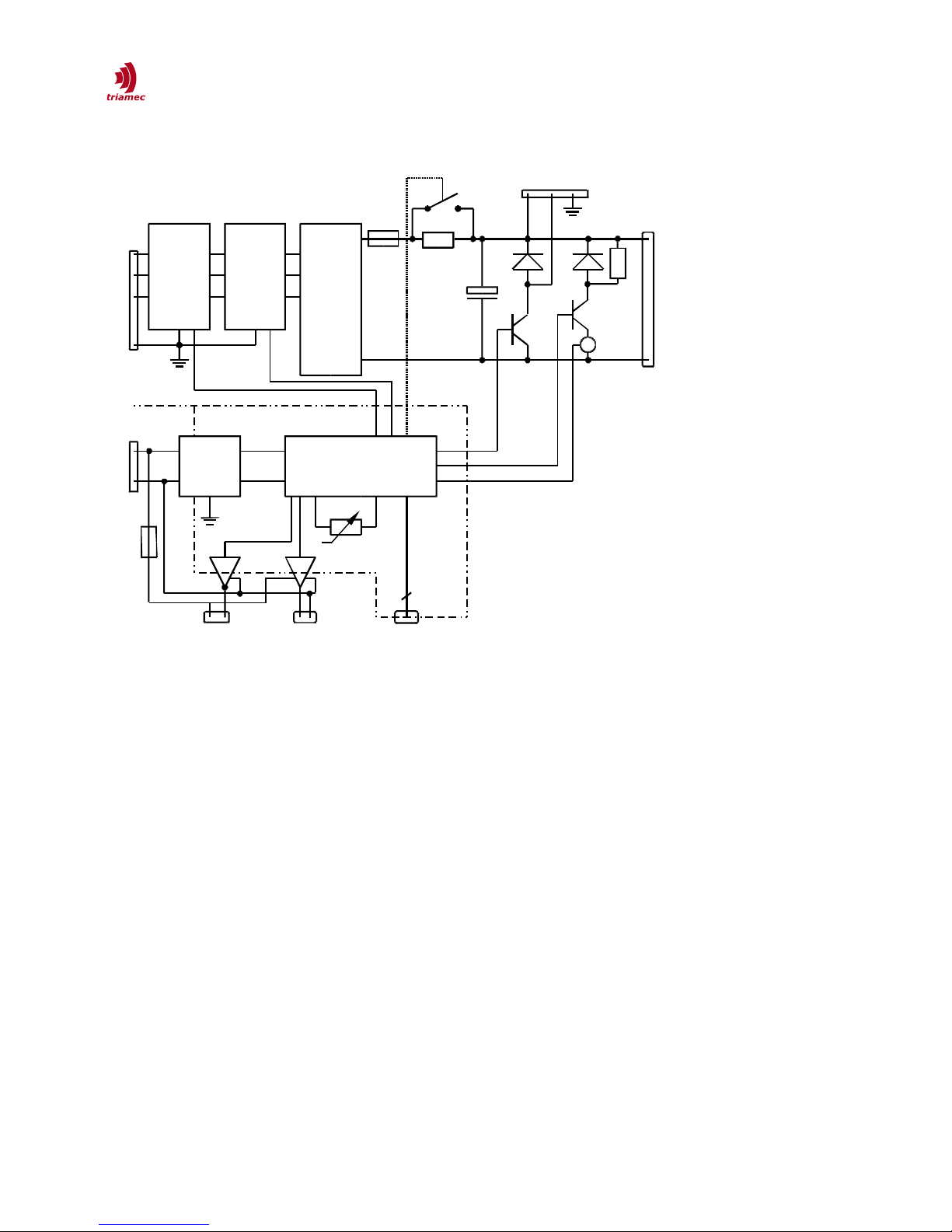
2.1 Block Diagram
Figure 1: lock Diagram
HWTP150-TP350_B_HardwareManual_EP017 2014-04-01 5/13
MOV
with
Monitoring
EMC
Filter
Rectifier
Fuse
Galvanic insulation
Controller
to four DC-Bus
Connectors
RS232
Config
DC Bus
Goo
Out
Ext. Brake
Resistor
AC-Line in
DC/DC
an
EMC
i
24V in
2 * Fan
Out
44
int. brake
+
-
Fuse

3 Technical Specifications
3.1 Environmental con itions
Transport and storage conditions
During the transport and the storage, the power supply must remain inside their original packaging
which complies with the ESD standard.
The transport conditions must respect the class 2K3 of the IEC 60721-3-2 standard (temperature
between -25°C (-13°F) and +70°C (+158+C), and humidity <95% without condensation) and
the storage conditions must respect the class 1K2 of the IEC 60721-3-1 standard (temperature
between +5°C (+41°F) and +45°C (+113°F), and humidity between 5 and 85% without
condensation). If either storing for more than two years or at temperatures higher than 35°C, ob-
serve the reforming procedure as shown under „Capacitor reforming“.
General Operating conditions
The power supply has the following electrical safety degree: IP 20 (according to EN 60529 standard).
The power supplies are designed to operate in a non-aggressive and clean environment, with a (non-
condensing) humidity ranging between 5% and 85%, an altitude < 2000m (6562 ft), and a temperature
ranging between +5°C (50°F) and +40°C (104°F).
The electronics must be in an enclosure respecting a pollution degree of 2 (refer to UL 508C and EN
61800-5-1 standards for more information). They are not designed or intended for use in the on-line
control of air traffic, aircraft navigation and communications, explosive atmosphere, as well as critical
components in life support systems or in the design, construction, operation and maintenance of any
nuclear facility.
HWTP150-TP350_B_HardwareManual_EP017 2014-04-01 6/13
3.2 Electrical Specifications
All the specifications are given for an ambient temperature ranging from +10°C (50°F) to +40°C (104°F)
and with the air flow cooling system of the TMPS4 mounting kit.
TP150 TP350
3-phase AC-Line input Nominal voltage UVN
AC voltage (between the phases)
Primary ULN of autotransformer (1)
110
25 to 1.1UVN
400
230
25 to 1.1UVN
400
V AC
V AC
V AC
Nominal frequency
Nominal maximum AC current IVN
Require External fuse maximum
Internal Dc-Bus Fuse (Fast)
Power factor correction
In-rush limiter
Insulation test voltage (2)
50-60
22
20 , e.g., Hager NBN320
30
no
300
360
Hz
A rms
A rms
A rms
Ohm
VDC
DC-Bus output DC voltage nominal
DC voltage maximum
150
185 ± 2%
325
380 ± 2%
V
V
Max current (sum)
continuous
pulse 30s
pulse 2s
14
20
25
A
A
A
Capacitance C 3.4 ±20% mF
Internal brake res. Break - point U_break_I
A iabatic issipation energy
Continuous power
180 ± 2%
1000
120
375 ± 2%
1000
120
V
J
W
External brake res Min Resistance
Setpoint U_break_E
15,
180 ± 2%
15
375 ± 2%
Ohm
V
24V logic supply (3)
PELV
Voltage
max current
Output Fuse (4)
24 VDC ±20%
100 + Fan and status output
1.1
V
mA
A
Fan connectors (4) Low si e switch 24V on/off, 1A
Status out (4) High Si e switch 24V on/off, 0.8A
Caution
Caution Before running an Insulation test or voltage test on a machine, disconnect all
connectors from Triamec drives.
Caution
Caution Mains input voltage drops at maximum load on the Dc-Bus side may break
the internal fuse due to capacitor recharging. Consult Triamec on how to
avoid this problem.
1 See chapter 3.3
2 Limited by an internal arrestor circuit.
3 The logic supply is galvanically isolated from the internal logic power. It can be switched on and off independently of the
AC-Line. It is, however, recommended to turn on the logic before the AC-line and turn it off after the AC-Line. Hot-plug -
ging is not recommended. Drawing DC-Bus current without logic supply is prohibited.
4 The fan and status outputs are galvanically connected to the 24V logic supply (see Output-fuse).
HWTP150-TP350_B_HardwareManual_EP017 2014-04-01 7/13

3.3 AC-Line
The power supply must be connected to an electrical network
of overvoltage category 3 (refer to EN 61800-5-1 and UL 840 standards for more information)
capable of delivering not more than 40kArms, symmetrical amperes (prospective current according
to EN 60269-1).
The network must be a TN-C-S with center earth or similar. In these cases, a transformer with com-
mon center (not insulating) is sufficient. An IT-net with phase on earth requires an isolating trans-
former. The same applies, if the network supplies more than 400VAC+15%, due to arrestor limits if
only one of three lines is connected and due to double isolation requirements. In this case, a trans-
former with common center is not allowed.
3.4 Discharge Currents
Caution
Caution Discharge currents (EN 50178, IEC 60755). If the primary side of this power
supply contains a residual current device for the protection of personnel
against electric shock, this device must be of type B according to EN50178.
Otherwise, alternative protection must be enforced, such as: insulation from
the environment by double isolation or using an isolation transformer.
3.5 EN 61800-5-1
The power supply confirms to EN 61800-5-1 (2008). Monitored varistors at AC-Line input and gas dis-
charge tube allow internal reduction of the overvoltage category III to II in the basic isolation part. Safe
electrical separation according to EN 61800 between the power circuit and 24V / Earth.
3.6 EN 61800-3
The interference suppression filter in this power supply complies to EN 61800-3 C2 under certain condi-
tions as detailed in the following.
The hardware manuals of the drives contain
Guidelines for proper shielding.
Restrictions on the motor and motor cable properties depending on the PWM frequency.
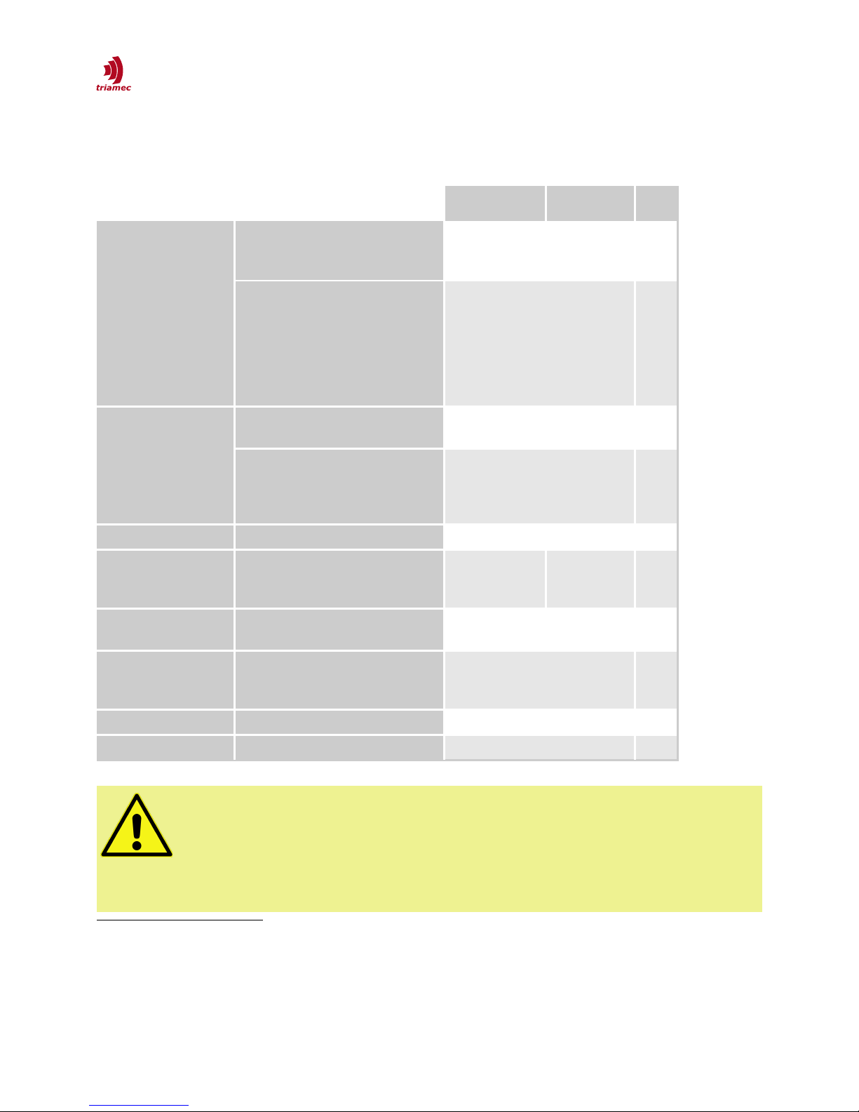
In the following table, capacity refers to the sum of cable capacity and motor capacity with respect to
earth. The table shows the total permissible capacity of all motors and motor cables attached to the
same power supply and the expected EMC class according to the standard EN 61800-3.
100 kHz ECO (50 kHz)
Capacity per Power Supply 8-12 (EMC C3)
<8 (EMC C2)
16-24 (EMC C3)
<16 (EMC C2)
nF
nF
Table 1: Permissible total capacity and expected EMC class
The critical requirement is the conducted voltage limit in the frequency range between 2MHz and
4MHz. Lower frequencies are not expected to break the C2 limit. Therefore a Ferrite (5) is supplied with
5 TDK ZCAT3035-1330 or similar.
HWTP150-TP350_B_HardwareManual_EP017 2014-04-01 8/13

every power supply, which is to be introduced around the three phase wires of the AC-Line. In some
cases it might be beneficial to insert further blocking ferrites (6) into the DC-Bus pairs. If doing so, make
sure, every DC-Bus output of the power supply gets its own ferrite to prevent overheating of the ferrite.
Other combinations of motors and cable might require a single stage line EMC filter or an insulated
transformer between 3x400V line-in and TP350.
3.7 Overvoltage
A system of a motor coupled with a load has a certain amount of energy. This energy is mainly kinetic
when the load is moving or rotating. While stopping these loads, the energy must either be stored or
dissipated. The same applies during moves when gravitational energy or spring energy is involved.
The drives recuperate this energy back to the power supply and the bridge voltage rises.
Internal brake capability
The following measures are provided internally of the power supply to store and dissipate energy. The
internal capacitors can store a certain amount of energy
Ec = 0.5 * C * (U2 - UdcSupply2)
Since the maximum voltage is given, the energy stored is defined by the rectified supply voltage UdcSupply.
See technical specification sheet.
Above UBrake-I, the internal brake will be activated to dissipate energy. This resistor can dissipate a short
term energy Eb but only a small continuous power Pb. If an external brake is missing or not properly de-
signed and high mechanical energy is involved the internal brake resistor might reach its thermal limit.
It will turn off and the DC-bus voltage might increase further until the drives turn off. Then the axis does
not stop and might cause mechanical damage.
This failure is avoided by adding an external brake resistor or reducing the deceleration of the drives.
Slower stopping reduces the load on the brake resistor. See section RS232 communication on how to
measure the internal state of the brake resistor.
External brake resistor
The external brake resistor must be dimensioned properly to account for the amount of energy to be
dissipated in the axis system if the internal resistor is not sufficient.
It is recommended to use a resistor that is protected against overtemperature. Contact manufacturer
for dimensioning.
Overvoltage protection
If the external braking resistor is not dimensioned properly, the DC-bus voltage may exceed the limit U d-
cMax. The drives will not be damaged because they protect themselves by turning off their semiconduct-
or switches. The axis is not decelerated anymore and the voltage will not increase any further. However,
turning off the drives during fast motion leaves the axis at the original speed. The axis might crash into
its end-limits, which might cause significant mechanical damage to the mechanical system.
Therefore it is important to choose a well dimensioned braking resistor. Also, the overvoltage error
message of the drives may be used by the control system for further information.
6 Würth 742 7010 or similar.
HWTP150-TP350_B_HardwareManual_EP017 2014-04-01 9/13

3.8 LED Diagnostics an Status
AC-Line DC-Bus Brake Int Brake Ext Status
No line power red flash off 0V
Inrush limiter green green flash 0V
Rea y green green 24V
AC-Line isturbance red flash green 24V
Discharging DC-Bus red flash green flash green flash 0V
Varistor broken all four LED moving red slow ( 1 per second) 0V
Internal brake active green
External brake active green
DC-Bus voltage excee e green alternate red flash green 0V
External brake short (*) red flash 0V
Over - temperature simultaneous blinking 4Hz 0V
Fuse Broken all four LED flashing 2 times then pause ones 0V
Internal error all four LED flashing 3 times then pause ones 0V
(*) cleared in state „no line power“
3.9 RS232 communication
Use the RS232 connection to check the internal state of the power supply, mainly the brakes.
Do not connect an active modem (Hyperterminal) during power-up or the power supply will enter
the firmware update state. If done unintentionally, power-off the power supply, disconnect RS232
and turn-on the hardware again.
Use a hyperterminal at 9600Baud (8data bits, no parity, one stop bit, no flow control).
Commands are one or two letters sent by the hyperterminal followed by „enter“. They are not case
sensitive.
? Show the list of the comman s
?i The SW version installed
LB Start the brake logger. The columns „D“ and „B“ show the DC-bus voltage in volt and the internal brake resistor
energy in Joule. If the adiabatic dissipation energy (see specifications) is reached, the internal brake resistor
will stop and only the external brake resistor continues running.
LV Start the Varistor logger showing voltages of Phases (R,S,T) against Earth and average voltage N and varistor
voltage V which should be the same as N.
LD Start the DcBus Logger showing voltages of DcBus N and P against Earth and their difference D.
L Stop logging
HWTP150-TP350_B_HardwareManual_EP017 2014-04-01 10/13

4 Mounting an Wiring
The power supply should be protected against any splashes of liquid and any contacts with smoke and
dust. It must be installed inside a closed cabinet and mounted as mentioned below.
4.1 Dimensions
Dimensions:
Width 91 mm
Height 205 mm
Depth 210 mm
The screw pattern is 100mm by 50mm.
4.2 Cooling
The maximum allowable ambient temperature is 40ºC. The TMPS4 mounting kit provides circulating air
to cool the power supply (and the drives). If this kit is not used, a minimum air speed of 3m/s is re -
quired at maximum current.
4.3 Brake resistor
Use only resistor with thermal shutdown protection. The use of an undersized power and energy with-
stand capability resistor might cause damage to the system. See section „Overvoltage“ for dimension-
ing.
Caution
Caution The cables connected to the external brake resistor must be shielded.
4.4 Capacitor reforming
Caution
Caution If the power supply has been stored without power for more than two years
after shipment or after last time use, the internal capacitors require reform-
ing. The same applies if storing above 35°C for more than one month without
power.
Solution: Add three series resistors 470Ohm/5W into the three phase power cable. Apply power for
half an hour without enabling the drives. Then shut down and disconnect for 4 hours, remove the
series resistors and the power supply is ready for use (7).
7 See the CECC 30302-809 detail specification and JIS C 5101-4 clause 4.1 for details.
HWTP150-TP350_B_HardwareManual_EP017 2014-04-01 11/13
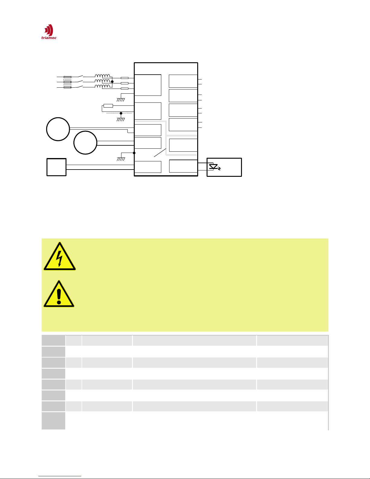
4.5 Wiring an Connectors
Supply TPx50
Fan 1
Fan 2
J1 DcBusP
DcBusN
J5
J6
U
V
W
PE
PE
Control
24VDC
Groun
Isolation
Mains
Switch Fuse
Mains Auto-
Transformer
L1
L2
L3
J2 DcBusP
DcBusN
J3 DcBusP
DcBusN
J4
UBreakN
UBreakP
J10
Fan
GND
J11
Fan
GND
J7
24V
GND
Ext.-Brake-Res
DcBusP
DcBusN
Drive 1
Drive 2
Drive 3
Drive 4
J8 RS232
J9 Status
GND
Ferrite
Figure 2: Power Supply Connections
The following measures must be taken to ensure personal safety and EMC requirements
There must be two earth connections. Each must have at least the same diameter as the AC-Line
wires.
The motor and encoder cable shield must be in firm contact with the earth at the drive and power
supply ground plate.
Danger
Danger
Must!
Must!
Always connect first the protective earth (PE) to the dedicated screws in the
top left corner of the housing!
Caution
Caution In a one phase configuration, never connect an European 230V phase L
without the corresponding neutral N. This might cause damage to the high
voltage protection circuit.
The TP350 is intended for 3x230VAC or lower. Never connect a European
3x400VAC power line.
Dir Name Connector Cross-section
J1-J4 out DC-Bus Sauro CGF029M7 1.5mm2 min, 2.5mm2 typ
J5 out External brake res. Sauro CGF039M7 1.5mm2 min, 2.5mm2 typ
J6 in AC-Line in Phoenix PC 5/4-G-7,62 (4 pins, Raster 7.62mm) 1.5mm2 min, 2.5mm2 typ
J7 in 24V logic supply Phoenix (or similar), 2 pins, 5mm pitch
J8 com Config RS232 9 pin sub-D female receptor, Pin3=RX
J9 out Status Out Phoenix (or similar), 2 pins, 3.5mm pitch
J10
J11
out Fan 1&2 Out Phoenix (or similar), 2 pins, 3.5mm pitch
HWTP150-TP350_B_HardwareManual_EP017 2014-04-01 12/13

PE Protective Earth M5 in the top left corner of the housing Same or larger than AC-Line
5 Warranty Information
The products covered in this manual are warranted to be free of defects in material and workmanship
and conform to the specifications stated either within this document or in the product catalog descrip-
tion. All Triamec Motion AG products are warranted for a period of 12 months from the time of installa-
tion, or 18 months from time of shipment, whichever comes first. No other warranties, expressed or
implied – and including a warranty of merchantability and fitness for a particular purpose – extend bey -
ond this warranty.
6 Revision History
Version Date E itor Comment
1.0 2010-08-18 mvx/up First edit
1.1 2010-10-06 mvx First delivery of Rev. B
1.2 2010-11-02 mvx Add RS232 communication
1.3 2010-11-18 mvx SW 1.1, Subversion 11102
1.4 2011-12-22 mvx Add warnings on single phase configuration
015 2012-11-30 mvx/chm Changed LED code for internal error, add logger Ld and Li. New document style
016 2014-03-22 mvx Extend chapter on EMC, discharge currents and earth and maximum current, add
requirement for external fuse.
017 2014-04-01 mvx Add wire cross-sections and PELV requirement for 24V, SW1.5
HWTP150-TP350_B_HardwareManual_EP017 2014-04-01 13/13
This manual suits for next models
1
Table of contents
Other Triamec Power Supply manuals


