Redexim Verti-Core III 1600 User manual

User Manual
and Parts Manual
Verti-Core III®
Model: 1600-2100
Serial number:
Translation of the original operating
instructions
Kwekerijweg 8
3709JA Zeist
The Netherlands
T: (31)306933227
F: (31)306933228
www.redexim.com
NOTE:
PLEASE READ THIS USER MANUAL CAREFULLY PRIOR TO USING THE
VERTI-CORE III® TO ENSURE SAFE USE OF THE MACHINE AND TO GET THE BEST
RESULTS.
1703 English 912.120.300

2
PREFACE
Congratulations on the purchase of your Verti-Core III. In order to ensure safe operation and a long life
span of this Verti-Core III it is crucial that you read and fully understand this user manual.
Without full knowledge of the contents of this manual, you will not be able to safely operate this
machine.
The Verti-Core III is not a stand-alone machine. It is the user’s responsibility to use a suitable tractor.
The user will also have to assess the tractor/ Verti-Core III combination’s safety aspects, such as
noise levels, user instructions and risk analysis.
On the following page you will find general safety instructions. Every user must be acquainted with
these instructions and apply them at all times. Below you will find a registration card, which you are
asked to return to us in order for us to be able to handle any future claims.
This User Manual provides a wide range of instructions which are numbered in a specific order. You
should always work in that order. If an instruction is accompanied by an icon, it is a safety
instruction. If an icon is used, the information in question is a tip and/or note.
All information and technical specifications provided at the moment that this document is published are
the most recent ones. Design specifications may be changed without prior notice.
This document is a translation of the original operating instructions.
Upon request, the original operating instructions are available in Dutch.
WARRANTY CONDITIONS
THIS VERTI-CORE III COMES WITH A WARRANTY AGAINST DEFECTS IN MATERIALS.
THIS WARRANTY IS VALID FOR A TERM OF 12 MONTHS FROM THE PURCHASE DATE.
VERTI-CORE III WARRANTIES ARE SUBJECT TO THE “GENERAL CONDITIONS FOR SUPPLY OF
PLANT AND MACHINERY FOR EXPORT, NUMBER 188”, AS PUBLISHED UNDER THE AUSPICES OF
THE UNITED NATIONS ECONOMIC COMMISSION FOR EUROPE.
REGISTRATION CARD
Complete the following table for your records:
Machine serial number
Dealer name
Purchase date
Notes

3
! SAFETY INSTRUCTIONS !
Fig. 1
The Verti-Core IIIis designed to facilitate safe
operation. But safe operation is only possible if all
safety instructions described in this manual are
observed without fail.
Read and understand (Fig. 1) the manual prior to
working with the Verti-Core III.
Failure to use the machine as described in the
manual can lead to a serious risk of physical
injury and/or damage to the Verti-Core III.
(1) The Verti-Core III is exclusively intended for the treatment of lawns or areas where grass should
be growing.
Any other use will constitute improper use. The manufacturer will not assume any liability for any
damage ensuing from improper use. Any risks involved in such improper use will be the full
responsibility of the user.
Proper use also includes the carrying out of operating, maintenance and repair instructions given
by the manufacturer.
Inspect the area you will be treating prior to using the Verti-Core III. Remove any loose obstacles
and avoid uneven areas.
(2) The Verti-Core III has been built in line with the latest technological advances to enable safe use.
Use, maintenance or repairs of the machine by untrained persons can give rise to a risk of injury
to the user and any bystanders. Avoid this at all times!
Always use the Verti-Core III in combination with a suitable tractor as described in the technical
data.
(3) All persons assigned by the proprietor to operate, maintain or repair the Verti-Core III must first
have fully read and understood the user manual, and, in particular, the Safety Instructions
chapter.
The user is responsible for a safe Tractor/Verti-Core III combination. The combination must
be assessed for noise levels, safety, risk and user-friendliness. User instructions for the
combination will also have to be drawn up.
(4) It is obligatory for the user to check the Verti-Core III for any visible damage and defects prior
to using it.
Changes to the Verti-Core III (including its functioning) that negatively affect safety, must be
remedied/undone right away.
Making any changes or additions to the Verti-Core III (except for those approved by the
manufacturer) is not permitted for reasons of safety.
If any modifications have been made to the Verti-Core III, its current CE mark will lapse, and the
party that implemented the modifications must secure a new CE mark himself.

4
Always check the Verti-Core III for loose nuts/bolts/parts prior to use.
Check any possible hydraulic hoses regularly, and replace them when they are damaged or
showing signs of excessive wear. Replacement hoses must meet the technical requirements
specified by the manufacturer.
The hydraulic system, if installed, must always be depressurized prior to working on it.
The Verti-Core III must NEVER be used when protective covers and safety stickers are missing.
NEVER crawl under the Verti-Core III.
If necessary, tip the Verti-Core III over.
NEVER get off the tractor when the engine is still running.
The Verti-Core III must always be secured against sagging/rolling away/sliding during
maintenance, setup and repair work.
Always switch off the tractor engine and remove the key from the ignition, and
disengage the PTO prior to any maintenance, setup and repair work.(Fig. 2)
Fig. 2
Only use original Verti-Core III parts during maintenance or repair work to safeguard the safety of
both machine and user.
Repair work on the Verti-Core III must only be carried out by competent and authorized technical
staff.
Keep a maintenance log.
(5) Apart from the instructions from this user manual, general occupational health and safety
instructions also have to be observed.
When going out onto public roads with the machine, relevant traffic regulations will also apply.
Transporting people is not permitted!
Do not use the Verti-Core III in the dark, in heavy rain/strong winds, or on slopes
above 20 degrees.

5
(6) Prior to working with the machine, all people who will be operating the Verti-Core III must be
acquainted with all its functions and control elements.
Hook up the Verti-Core III to the tractor as per the instructions (Danger of physical injury!)
Make sure you have good visibility, both close by and of the entire surroundings, prior to setting
off.
There are safety stickers on both sides of the Verti-Core III (Fig. 3,4,5) as well as on the back(Fig. 6),
which all have the same meaning. These safety stickers must always be visible and readable, and
they must be replaced without delay whenever they are damaged.
Keep all people out of the danger area of the Verti-Core III during operation, because they
would otherwise be subjected to serious danger of personal injury caused by moving parts. (Fig. 3)
Fig.3
Fig.4
Maintain a distance of at least 4 metres! (Fig. 4)
The back cover has to remain closed at all time and be damage-free during operation of the
machine! (Fig. 5)
Beware of body parts getting caught when opening the back cover! (Fig. 5a)
Fig. 5
Fig. 5a
Check the permitted lifting power of the tractor.
Wear appropriate clothing. Wear sturdy steel-capped shoes, full-length trousers, long hair tied back and
no loose garments.

6
(7) Location of safety stickers. (Fig. 6)
Fig. 6
All safety stickers have to remain on the machine at all times - and be fully
understood by the operator.
Used oil is harmful to the environment; dispose of it in line with local regulations.

7
EU DECLARATION
We,
Redexim BV
Utrechtseweg 127
3702 AC Zeist, Holland
hereby declare under our own full responsibility that the product:
VERTI-CORE III WITH MACHINE NUMBER AS INDICATED ON THE MACHINE AND IN THIS
MANUAL,
to which this declaration refers, complies with stipulation of the 2006/42/EC machine directive and is in
conformity with the following standards: NEN-EN-ISO 12100 : 2010 NEN-EN-ISO 13857 : 2008
Zeist, 06/02/2013
A.C. Bos
Manager Operations & Logistics
Redexim Holland

8
TABLE OF CONTENTS
PREFACE..........................................................................................................................2
WARRANTY CONDITIONS...........................................................................................................2
REGISTRATION CARD.................................................................................................................2
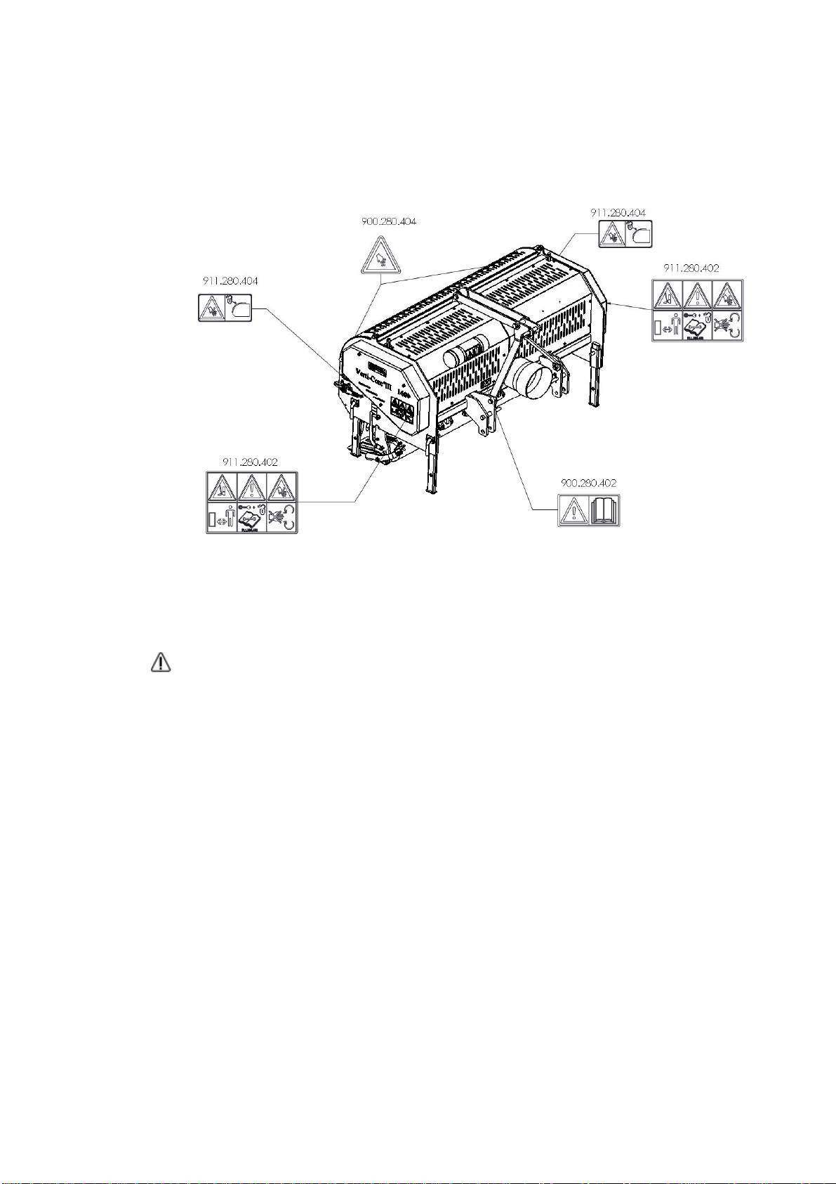
! SAFETY INSTRUCTIONS !...............................................................................................3
EU DECLARATION .......................................................................................................................7
1.0TECHNICAL DATA.............................................................................................................9
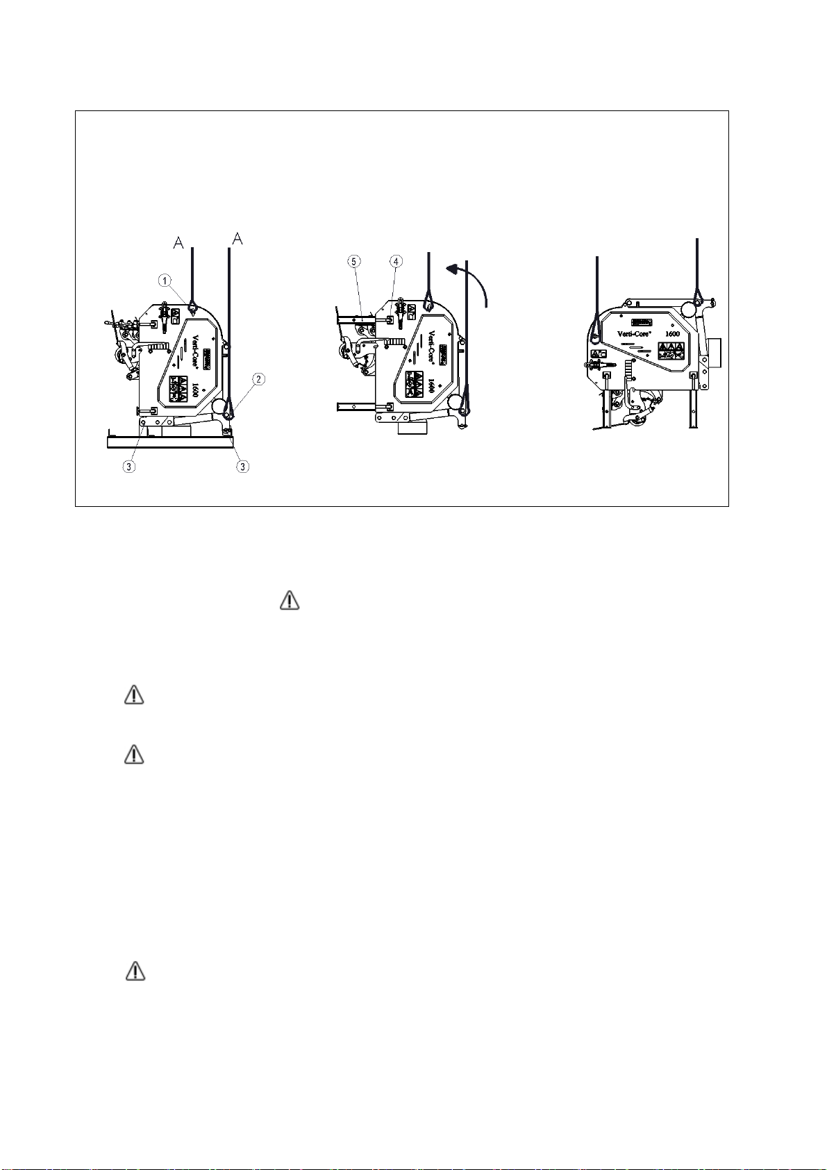
2.0TAKING THE MACHINE OFF THE PALLET....................................................................10
3.0THE PTO...........................................................................................................................11
3.1PTO LENGTH...................................................................................................................11
3.2PTO USE ..........................................................................................................................12
3.3PTO INFORMATION AND MAINTENANCE.....................................................................12
4.0CONNECTING TO THE TRACTOR .................................................................................14
5.0SETTING THE WORKING DEPTH...................................................................................15
6.0DRIVING SPEED..............................................................................................................16
7.0STARTING PROCEDURE...............................................................................................16
8.0USING THE VERTI-CORE III ...........................................................................................17
9.0TRANSPORTING THE VERTI-CORE III..........................................................................18
10.0DISCONNECTING THE VERTI-CORE III.........................................................................19
11.0TROUBLESHOOTING......................................................................................................20
12.0MAINTENANCE................................................................................................................21
13.0LUBRICATION PIONTS....................................................................................................22
14.0V-BELT TENSIONING......................................................................................................23
15.0TECHNICAL INFORMATION............................................................................................24
15.1REPLACING A CRANK/CONNECTING ROD BEARING.................................................24
15.2RELEASING CRANKSHAFT TENSION...........................................................................25
15.3TIMING AND TORQUES..................................................................................................25
16.0OPTIONS..........................................................................................................................27
16.1HOLLOW TINES...............................................................................................................27
16.2TURF HOLD DOWN FINGERS........................................................................................28
16.3WINDROW KIT.................................................................................................................28

9
1.0 TECHNICAL DATA
Model 1600
2100
Working width 1.6 m (63”)
2.1mtr (83”)
Working depth 0mm - 100mm (0”-4”)
Tractor speed measured at 540
rpm on power take-off (PTO)
shaft
Hole spacing 55 mm (2.2”)
Hole spacing 110 mm (4.3”)
Up to 1.8 km/h (1.2 mph)
Up to 3.6 km/h (2.4 mph)
Weight 846 Kg (1865 lbs)
1022 Kg (2253 lbs)
Recommendations for tractor 45 HP with minimum lifting
capacity of 1000 Kg (2205lbs)
55 HP with minimum lifting
capacity of 1250 Kg (2755lbs)
Tine spacing 55 mm (2.1”) @ 19mm (0.75”) holes
68,75 mm (2.7”) @ 22mm (0.87”) holes
Hole spacing in driving direction 25 – 110 mm ( 1” – 4.3”)
Maximum capacity
Hole spacing 55 mm (2.2”)
Hole spacing 110mm (4.3“)
Up to 2880 m²/h (31000 ft²/h)
Up to 5760 m²/h (62000 ft²/h)
Up to 3780 m²/h (31000 ft²/h)
Up to 7560 m²/h (62000 ft²/h)
Shipment dimensions L x W x H
1960 x 1040 x 1110 mm
77” x 41” x 43.7”
L x W x H
2581 x 1100 x 1080 mm
102” x 43.3” x 42.5”
3-point hitch CAT. 1
Gearbox oil SAE 90
Lubricant EP 2
Standard parts -Set hollow tines 13/16” with
¾”” mounting
-Roller.
-Tool case with tools and user
manual.
-PTO shaft.
-Turf hold down fingers
Set hollow tines 13/16” with
¾”” mounting
-Roller.
-Tool case with tools and user
manual.
-PTO shaft.
-Turf hold down fingers
Options -7/8” Tine holders with 4 tines

10
2.0 TAKING THE MACHINE OFF THE PALLET
Fig.7
The machine is placed on the pallet vertically. Perform the following actions to remove the machine
from the pallet and place it horizontally on the floor (see Fig.7):
!! NEVER CRAWL UNDER THE MACHINE !!
1. Attach a cable to the lifting points (1) on both sides of the machine, and to the top of the 3-point hitch
(2) on the front.
Verti-Core III 1600 Make sure the cable/crane/lift has the capacity to lift at least 1700 kg
(3750 lbs).
Verti-Core III 2100 Make sure the cable/crane/lift has the capacity to lift at least 2100 kg
(4630 lbs).
2. Lift the machine, including the pallet, about 50 mm (2”) off the ground (A).
3. Remove the pallet by removing the bottom 3-point pins (4).
4. Pull the pallet from under the machine (B).
5. Turn de locking pins (4) half a rotation and remove them. Pull out the legs (5) and replace the locking
pins.
6. Now slowly rotate the machine horizontally.
7. Lower the machine in a controlled and slow fashion until it is fully on the ground.
!! STAY CLEAR OF THE MACHINE, IT CAN SLIDE !!

11
3.0 THE PTO
The PTO is an essential part of the machine. This part drives the machine from the tractor, and ensures safe
use of the machine, providing it has been maintained and installed correctly. The PTO has its own CE
certification. Read the PTO manual, which you will find on the PTO itself.
Fig. 8
3.1 PTO LENGTH
The length of the PTO is crucial. If it is too long, the tractor and/or Verti-Core III can be damaged.
When the overlapping length of the sleeves drops below 150 mm (6”) at any time, the PTO can be damaged.
(Fig 8)
!! PTO length will change when the machine is lifted or used on a different tractor!!
In order to attain the right PTO length, when one has been purchased new or was previously used on another
tractor, you will have to do the following:
1. Couple the Verti-Core III to the tractor as described in Chapter 4.0.
2. !! Switch off the tractor and make sure the tractor is secure and cannot start moving !!
3. Lower the Verti-Core III onto the floor until it is resting on the front and back rollers.
4. Measure the distance A between the PTO connection of the tractor and that of the Verti-Core III, from
groove to groove.
5. Measure length B of the PTO in its shortest position, from locking pin to locking bolt.
6. Split the PTO in two, and remove the protective cover from both ends.
7. Both the ends of the sleeves and of the safety covers have to be shortened: (B-A) + 75 mm (3”).
8. De-burr all parts, use some grease and assemble the parts.
9. Mount the PTO on the Verti-Core III side.
10. Couple the other end of the PTO to the tractor.
11. Check sleeve overlap.
!! Never use the machine with a damaged PTO protection cover; Replace it first!!

12
3.2 PTO USE
Proper use of the PTO requires checking the following items:
1. While the Verti-Core III is operating, the angle of the pivoting points must never exceed 30
degrees.
2. Pivoting points must always be in line.
3. Sleeve overlap must be at least 150 mm.
4. Never use the machine with a damaged PTO protection cover.
3.3 PTO INFORMATION AND MAINTENANCE
The slip clutch, when used and maintained correctly, will protect your machine against damage.
The following items are important here:
1. The length of the spring is set to 33 mm (1.300”) as standard.
2. When the slip clutch slips, the bolts/nuts can be tightened a further quarter turn, up to a minimum
spring length of 31.5mm (1.250”). Further compression will subject the machine to excessive load.
When bolts/nuts are tightened too much, the machine could eventually sustain damage, or unsafe
situations could occur.
3. The slip clutch must be maintained on a monthly basis. Do so as follows:
- Remove the top PTO protection cover from the machine.
- Loosen all bolts/nuts 2 turns.
- Operate the machine on the lawn at low speed.
- If the clutch slips, stop the machine after 10 seconds.
-If the clutch is not slipping, further loosen the bolts or move on to (annual) maintenance (see
point 4 below)
- If the clutch has slipped, tighten the bolts/nuts up to the point at which the slip clutch functions
properly again.
* Do not immediately turn it back to as it was in the previous setting.

13
4. Annual maintenance:
- Remove the PTO from the machine
- Inspect the PTO components. All damaged parts must be replaced.
- Disassemble the slip clutch by removing all spring assembly bolts/nuts; the slip clutch
should then fall apart.
- Lay all parts down and check them closely. Replace any damaged and worn parts.
- Clean all intermeshing parts.
- Reassemble all parts, and tighten the bolts and nuts so that the springs are set at 33 mm
(1.3”).
- Grease both sleeves and put both PTO parts back together.
- Reassemble the PTO and mount it on the machine.
- Adjust, if required, the springs of the slip clutch as described above.
The slip clutch only protects the machine against short periods of overload when it is set
correctly. Prolonged overload will damage the machine. The slip clutch will not protect the
machine against that. Be sure to avoid overload on your machine.
Please refer to the manual with the PTO for further information on PTO maintenance and
disassembly.
If the PTO is shortened incorrectly, or another tractor is used, the gearbox can be
subjected to excessive load. This can lead to damage to both the tractor and Verti-Core III!

14
4.0 CONNECTING TO THE TRACTOR
Checks prior to connecting the Verti-Core III.
Check the Verti-Core III for any visual damage, and repair if safe operation of the
machine cannot be guaranteed.
Check whether all nuts and bolts have been tightened properly.
Check whether all protective covers and safety stickers are in place on the machine,
and whether they are undamaged.
NEVER use the machine without them.
Fig. 9
The Verti-Core III can be connected to the tractor using the 3-point hitch.
The method is as follows: (Fig. 9)
1. Remove the 3-point pins (1 and 2).
2. Mount the PTO on the PTO shaft of the Verti-Core III.
3. Carefully back up the tractor, so that the lifting arms can be connected to the frame.
!! Make sure the tractor is secured in place and cannot start moving!!
!! Switch the tractor off prior to getting off!!
4. Connect the lifting arms to the bottom 3-point pins (2) and secure them using the
included locking pins.
5. Set the stabiliser of the tractor to a 100 mm sideways stroke.
6. Mount the top link of your tractor and extend it until it is at the same height as the top 3-
point hitch (1) of the Verti-Core III.
7. Connect the top link (3) to the frame using the top pin (1) and secure using the included
locking pin.
8. Keep extending/retracting the top link until the machine makes a 90° angle with the
ground.
9. Mount the PTO (4) on the tractor’s PTO shaft.
!! Make sure all locking pins are secured!!
10. Start the tractor and lift the Verti-Core III off the ground.
11. Place the support legs (5) in the working position

15
5.0 SETTING THE WORKING DEPTH
Fig.
10
The
wor
king
dept
h
can
be
set
whe
n
the
mac
hine
is
lifte
d off
the
grou
nd.
(see Fig.10)
The procedure is as follows:
!! Make sure the tractor/Verti-Core III are secured in place, and cannot start moving !!
!! Switch the tractor off prior to getting off !!
1. Unscrew the nuts (1) on both sides of the machine a few turns.
The machine comes with a set of spanners; you can find these in the tool case
(4).
2. Set the spindles (2) using the provided spanners, which will change the working depth.
Stickers (3) on the side of the machine indicate the depth setting on both sides of the
machine.
3. As soon as the right working depth has been achieved, you can tighten the nuts (1) on
both sides.
4. Check whether the setting is the same on both sides.
Never change the setting on one side by more than 4 turns. First compensate on the other side,
before proceeding.
! IMPORTANT!
Check the working depth first in a static situation on the ground before actually starting the
work!

16
6.0 DRIVING SPEED
Driving speed is limited to 12 km/h (7.5mph).
We advise against going any faster because that could lead to excessive wear and damage to the
machine and the treated lawn.
Hole spacing in the driving direction is determined by the driving speed.
The input speed of the PTO shaft must not exceed 540 rpm. If you expect to encounter any hard
objects on your path, this speed should be lowered to 200-300 rpm.
Refer to technical specifications for an overview of the relation between tractor speed
and hole spacing.
If the Verti-Core III is connected to the tractor incorrectly, Chapter 4, Fig.11, different
PTO shaft angles can cause vibrations in the machine’s drive shaft. These vibrations can
damage the machine and negatively affect the pattern of holes in the ground.
If the PTO shaft length is set incorrectly (too short or too long), the gearbox and/or
tractor PTO shaft can be subjected to additional load. This can cause damage.
7.0 STARTING PROCEDURE
The starting procedure is VERY important. If this procedure is not adhered to as described below, the
machine can become seriously damaged. The starting procedure is as follows, see Fig. 11.
1. Drive to the spot where you want to start the work.
2. Lower the machine until the lowest tines almost touch the ground.
3. Rev the tractor engine up to about 1000 rpm.
4. Shift the tractor to the right gear and drive forward (A).
5. Switch on the PTO shaft of the tractor (B).
6. CAREFULLY lower the RUNNING machine into the ground as the tractor is moving forward (C).
7. Raise the PTO shaft rpm to the maximum permissible value.
Fig. 11

17
Stop as follows:
1. Lower the engine rpm to about 1000.
2. Raise the machine from the ground.
3. Disengage the PTO shaft, as soon as the tines are out of the ground.
4. Raise the machine further, until the tines are at least 120 mm above the ground.
5. Go to the next spot and start again as described.
It is absolutely necessary to follow the procedures described above. If the machine is
placed in the ground first, with the PTO shaft not yet running, this can lead to serious damage
to the machine.
Lower the machine into the ground CAREFULLY.
Be careful when reversing.
During the work, the front roller must rest on the ground in a stable manner. If the machine is
unstable, fit different tines or change the working depth.
Not doing anything about machine instability will cause damage to the machine. The
machine is NOT protected against prolonged overload.
NEVER reverse with the tines in or near the ground.
NEVER reverse with the tines less than 120 mm above the ground. If the tines touch the
ground, the machine and/or the lawn will be damaged.
Do not use a hydraulic top link.
8.0 USING THE VERTI-CORE III
Before the Verti-Core III can be used on a lawn, the following must be checked:
1. Are there any loose objects on the lawn? If so, remove these first.
2. Are there any slopes? The maximum slope on which the machine can function properly is
20 degrees.
Always work from the top down.
3. Is there any danger of objects flying around, such as balls, which could distract the
operator? If so, do NOT use the Verti-Core III.
4. Is there any danger of subsiding, sliding? If so, postpone the work until circumstances
improve.
5. When the ground is frozen or very wet, the work should be postponed until conditions have
improved.
6. Are there any cables/pipes in the ground? If so, find out at what depth they are, and set the
working depth to 60% of that depth.
7. Are there any hard objects in the ground? If so, use the Verti-Core III at a low PTO shaft
speed, and adjust the working depth.
8. If the ground is very compacted, you should use shorter tines or adjust the working depth.

18
9.0 TRANSPORTING THE VERTI-CORE III
The user is responsible for the transport of the Verti-Core III behind the tractor on public roads. Check
national legislation for regulations for driving on public roads.
Do not exceed a speed of 12 km/h on open fields, due to the weight of the Verti-Core III.
Higher speeds can pose a serious danger to the operator/bystanders, and could possibly damage the
machine.
Make sure the top link (3), see Fig. 10, is connected and tensioned in the conveyor. If
this is not case, the machine could sustain serious damage.
When the machine is lifted off the ground, at least 20% of the weight of the tractor
must rest on the front axle.

19
10.0 DISCONNECTING THE VERTI-CORE III
Fig.12
The machine can be disconnected from the tractor in the following way (See Fig 12):
1. Drive the Verti-Core III to a storage space with a stable/even floor.
!! Make sure the tractor is secured in place and cannot start moving !!
!! Switch the tractor off before getting off !!
2. Turn the locking pins (2) halve a rotation and remove them.
3. Lower the support legs (1).
4. Secure the support legs (1) by replacing the locking pins (2).
5. Carefully lower the Verti-Core III to the ground.
6. Release the top link and remove it.
7. Remove the locking pin (4), remove the top link connection pin (5)
8. Remove the locking pin (7), remove the connection pins (6). Disconnect the bottom lifting arms from
the tractor.
9. Disengage the PTO on the tractor side.
!! Make sure the Verti-Core III is stable and cannot roll/slide away!!
10. Start the tractor, and drive it away.

20
11.0 TROUBLESHOOTING
Machine vibrates Crankshaft turns irregularly
Difficult conditions
Machine not at 90 degrees
Angles of PTO pivoting points
differ
PTO pivoting points not in line
Adjust working depth
Use thinner/shorter tines
In case of dryness, sprinkle
first
Hollow tines bend/break Wrong tine
Difficult conditions
Change tines, use shorter
ones.
First break the ground using
another machine.
Adjust working depth
Use thinner/shorter tines
In case of dryness, sprinkle
first
Front roller not stable on the
ground Wrong tines, too much
resistance
Difficult conditions
Change tine size
Adjust working depth
Use different tine size.
Adjust working depth
Sprinkle first
PTO breaks Sleeves crack PTO angles too big
PTO angles do not match
Damage to the lawn Oval holes
Damage to the lawn
Ground too wet
Decrease forward speed
Decrease working depth
Use Turf Hold Down Fingers
Irregular pattern of holes (One) slipping V-belt
Rubber buffers worn
Check V-belt tension
Check pretension and replace
Change PTO rpm
V-belt/belts slip V-belts / pulleys worn
Insufficient pre-tensioning
Difficult conditions
Check and replace
Check and replace
Adjust working depth
Decrease forward speed
Use thinner tines
This manual suits for next models
1
Table of contents
Other Redexim Lawn And Garden Equipment manuals

Redexim
Redexim BLEC POWER BOX RAKE 80 User manual

Redexim
Redexim RINK S 510 Product manual

Redexim
Redexim Verti-Drain 7007 Hydro User manual

Redexim
Redexim VERTI-CUT 1600 User manual

Redexim
Redexim Combi-Groom User manual

Redexim
Redexim Verti-Drain 7007 User manual

Redexim
Redexim 7117 Product manual

Redexim
Redexim Speedseed Walk Behind User manual

Redexim
Redexim Vibra-Sandmaster 1600 User manual

Redexim
Redexim Verti-Drain 7113 Product manual