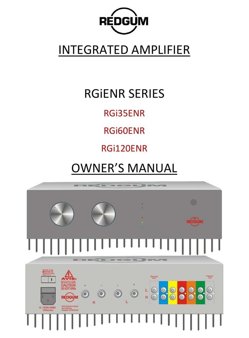
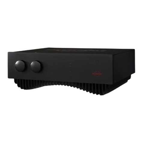
Redgum RGi35ENR User manual

!"#$%&


!
"
!

#

$%&'(&%)*'*+,-.*&
'/
,!!0
!!!!!!
1+ !!!
&*'-2)$ !!
!&! !
03!!!
0
4!
5"!
'),
6!1
(,!03)%+(*!
!
$!1+!
!$0!!
2(7+ !!!0
!!!,!!
689:!!&)+1
7!*),
!! !
'! 1+ ;0
< !
%")!"0
!!0
==!
%
>
,&
?

$"+,.*/$&%.
> 1+ !0! 703
!!!
@!
!
!A
!!B
$/!B
7B
!
!!! !
03!!
!
C

CONNECTIONS
The amplifier is heavy. Place it on a sturdy and stable surface.
The rear panel is equipped with five sets of line-level inputs, each identified with a different
colour. Insert the RCA cables for each source device into the input you have chosen for it. The
bottom RCA socket (red) is for the right channel, and the top RCA socket (white) is for the left
channel.
If you have a turntable ensure that the signal from its pickup cartridge is first connected to a
phono pre-amp such as the REDGUM RGPH2ENR. The output of the phono pre-amp can be
connected to any of the inputs on the back of your amplifier.
Connect ‘Record Out’ to an audio recording device. Connect ‘Preamp Out’ to other amplifiers
such as a pair of power amplifiers, a single active subwoofer, or a pair of active subwoofers.
Note: Any of the line-level inputs can be used to provide a Home Theatre ByPass.
The coloured line-level inputs on the back of the amplifier correspond to the indicator lights
on the front panel. These indicator lights show you by colour which source input has been
selected.
Page of7 18
Mute & source
indicator lights
Line-level"
inputs
Standby"
switch
To loudspeakers
IEC power
socket
Record
Out
Preamp
Out

Always use high-quality interconnects such as REDGUM Audio Pipeline or REDGUM OCC Pure
Silver.
Use a high-grade speaker cable (such as REDGUM’s Expressive-Line) to connect the amplifier’s
terminals marked ‘R’ and ‘L’ to your speakers. The ‘+’ and ‘−’ signs indicate the polarity of the
signal. By convention the red lead should be connected to ‘+’ while the other lead (typically
black) is connected to ‘−’. At the other end of the cable, connect the red and black leads to the
speaker terminals marked ‘+’ and ‘−’ respectively.
You are now ready to power-on the amplifier.
CONNECTING TO MAINS POWER
1. Ensure that both volume control knobs on the front of the amplifier are fully turned
down, i.e., turned fully counter-clockwise.
2. Set the red standby rocker switch (above the power socket on the rear of the amplifier) to
the ‘OFF’ position.
3. Insert the IEC power connector into the power socket.
4. Plug the mains power cord into a wall socket (or your AC power distributor, if you are
using one) and switch it on. Note that the rocker switch is lit from within.
5. Now, set the standby rocker switch to the ‘RESET’ position. This energises the
microprocessor that manages and monitors the amplifier’s health and functions. After
two seconds the amplifier will go through the following Power-On Self-Test sequence:
• The red LED within the REDGUM logo on the lower right of the front panel will be lit.
• The amplifier will emit a beep tone followed by a rising tone.
• The amplifier will emit three rapid beeps, three times. On the front panel, the red LED at
the top of the vertical array of Source Input LEDS - indicating the ‘Mute’ function - will
flash with each beep.
• The source input LEDs will flash in sequence from top to bottom. Each flash is
accompanied by a clicking sound. These are the source input selector switches being
‘cleaned’.
• Two soft thumps will be heard from the loudspeakers, first from one speaker then from
the other speaker. This is normal and safe, and due to the controlled energising of
amplifier’s left and right output stages.
• The volume controls are moved to the setting previously in use when the amplifier was
last powered off. If that volume position was very high then the amplifier will move the
volume controls to a safe lower level.
Page of8 18

At this point the Power-On Self-Test sequence has been completed. The amplifier is now in
Standby mode. The red LED within the REDGUM logo will remain lit as long as the Standby
switch (on the rear) is in the ‘RESET’ position, This is regardless of whether the amplifier has
been powered on or offvia the remote controller.
USING THE REMOTE CONTROLLER
Prepare the remote controller for use by pulling out the clear plastic tab from the bottom
edge. This allows the battery to supply power to the controller’s electronics.
Powering On/Off
• To power-on the amplifier, point the remote controller at the amplifier’s front panel, then
press the red ‘Amp Power’ button on the top-left of the controller. The LED indicating the
source last selected will light up, and the volume controls will be moved to the position
they were at when that source was last in use. As a Power-On indicator, the light of a blue
LED underneath the amplifier can be seen through the SignWave heat sink.
• To power offthe amplifier, point the remote controller at the amplifier’s front panel then
again press the red ‘Amp Power’ button (i.e., this button toggles on/off). The unit will go
back into Standby mode, and the blue LED underneath the amplifier will turn off."
"
The amplifier draws very little power (between 0.1W to 0.25W) when in standby mode, so
there is no need to turn offthe mains power.
Selecting the Input Source
The picture below shows how the colour-coded line-level inputs on the rear of the amplifier
correspond with the LEDs on the front panel (if read from the top down), and with the source
labels on the remote controller (read from left to right).
Page of9 18
SOURCE INPUT
LABEL ON REMOTE
CONTROLLER
COLOUR OF LINE-
LEVEL INPUT AND
LED
CD1
Blue
AV1
Yellow
DVD
Red
CD2
Orange
AV2
Green
CD1
AV1
DVD
CD2
AV2
Mute

Volume & Balance Control
The instructions below refer to the cluster of remote controller buttons containing the four
blue-coloured arrow buttons.
The buttons below the arrow cluster are for controlling REDGUM Audio CD players equipped
with the remote control feature.
Increase volume
Press the blue ‘up’ arrow button.
Decrease volume
Press the blue ‘down’ arrow button.
Shift the audio image left
Press the blue ‘left’ arrow button.
Shift the audio image right
Press the blue ‘right’ arrow button.
Centre the audio image
Press the silver ‘Bal’button.
Mute the volume
Press the silver ‘Mute’ button. Note: Mute is partial (-15dB).
Un-mute the volume
Press the silver ‘Mute’ button.
Check if the remote controller’s
battery needs to be replaced
Press the silver ‘Magic’ button while the amplifier is powered on. With a
healthy battery, the‘Mute’ indicator should flash and click continuously as
long as the button is held down. If this is not the result, replace the battery
with one from a quality “name” brand.
Page of10 18

TROUBLESHOOTING
If the problem cannot be resolved by any of these recommended actions you should make
certain that the problem lies with the amplifier, as malfunction within other components may
also be the cause of the symptoms. You can do this by borrowing a CD player and speakers
that you are certain are working, and replace your normal components with these to test the
amplifier in isolation. Please contact your local REDGUM Audio dealer if the problem persists.
Thermal Cut-off
There are no replaceable thermal fuses in REDGUM amplifiers. Unlike other amplifiers, all
REDGUM amplifiers are protected against internal overloads by a thermal sensor. The thermal
sensor will shut down the amplifier if the heat sink’s temperature reaches approximately 60ºC/
140ºF. This usually happens only if the speaker leads remain ‘shorted’ together for a period of
time.
The warning of such an event is given by the behaviour of the blue Power-On indicator LED,
which shines downwards through the fins of the SignWave heat sink base.
Normal operation: This LED will be lit continuously when the heatsink is within its normal
operating temperature range.
Near thermal cut-off:The blue LED will start to flash slowly at approximately 50ºC/122ºF,
indicating that the heat sink’s temperature is rising. The frequency of flashes increases as the
temperature approaches the thermal cut-offtemperature of approximately 60ºC/140ºF.
SYMPTOM
LIKELY CAUSE
RECOMMENDED ACTION
No sound.
The amplifier is not turned on, or
is not connected to the power
outlet.
Check that the amplifier is plugged into
the power outlet, and turned on.
The sound of a particular
input source is not heard.
Improper connections. If on all
inputs, check Mute button status.
Make sure that the external component
is connected correctly.
Stereo image is vague/bass
response is lacking.
Speakers out of phase.
Check that the correct + to + and – to –
connections have been made between
the amplifier and your speakers.
Buzzing or crackling sound
when connecting wires.
Equipment is turned on.
Turn offall equipment before making
any cable connections.
Distortion at low volumes.
Speaker wires are touching each
other, or another terminal, and
shorting the signal."
"
Amplifier is damaged.
Ensure that all cable connections are
clean with no loose wires.
Check/repair amplifier.
Distortion at high volumes.
Amplifier is overloaded.
Turn down the volume to avoid damage
to your speakers and amplifier.
Page of11 18

After thermal cut-off:The amplifier will emit a repeating sequence of flashes/beeps.
•A sequence of 4 flashes+beeps followed by no light/sound for 4 seconds indicates that
you should power down the amplifier. Once the amplifier has returned to a safe operating
temperature, its operation can be resumed by using the remote controller to power-on
the amplifier.
•A repeated sequence of 5 flashes+beeps indicates that the thermal sensor is not able to
reset itself, and that you should contact your local REDGUM dealer for a service call.
Circuit Breaker Rocker Switch
The ‘Standby’ switch (red rocker with RESET and OFF positions) above the IEC mains socket on
the rear of the amplifier’s chassis is actually a circuit breaker. In the unlikely event of a mains
power overload or an internal malfunction, the circuit breaker will activate (‘trip’). The switch
will automatically rock to the OFF position, and will be lit from within.
In the case of a mains power overload, rocking the switch to the RESET position will turn on
your amplifier again. Once reset, the red light in the ‘Standby’ switch will turn off, the amplifier
will go through its full Power-On Self-Test sequence, and the red LED within the REDGUM logo
on the front panel will be lit.
However, if there is an internal malfunction, it will not be possible to reset the switch.
Attempting to do so will cause the switch to instantly flick back to the OFF position, and the
switch will remain lit. Please seek professional service should this occur.
Consult your local REDGUM dealer if in any doubt whatsoever!
Not Enough Volume?
If you have pressed the Up/Down volume buttons on your remote controller but the resultant
change in volume does not match previous adjustments, do a quick visual check to see if the
amplifier’s ‘Mute’ setting is On. If ‘Mute’ is On, the red LED at the top of the vertical array of
source indicator lights will be lit. If the “Mute” is Off, no light is visible in this position.
The ‘Mute’ button does not completely cut offthe volume. Instead, the ‘Mute’ is partial,
dropping the volume by approximately 15dB. This allows you to quickly attain background
music levels whilst talking, or to hear the sound cues of a TV programme returning without
needing to watch a silent screen throughout an ad break.!
Page of12 18

WARRANTY
Your warranty can be registered directly via the REDGUM Audio website: http://
www.redgumaudio.com/warranty-registration/.
If you prefer, the details (including the amplifier’s Serial Number) on the next page can be
If you are not the original owner of this REDGUM product, feel free to send your unit’s details
to owners@redgumaudio.com or your local REDGUM representative so that you can be placed
on the REDGUM Owner’s Register. We and our representatives welcome your feedback and
would be happy to include you on our REDGUM Updates email list.
REDGUM amplifiers are warranted to be free of defects in material and workmanship, subject
to the following conditions and limitations, for SEVEN (7) years from the date of purchase by
the original owner. Warranty claims must be accompanied by proof of purchase, including
date.
This warranty is void and inapplicable under the following conditions:
A. The amplifier has not been used in accordance with the instructions in this owner’s
manual.
B. The amplifier has been subject to misuse or abuse, one example of which would be
damage consistent with the speaker terminals being connected to another electrical
source.
C. The amplifier has been modified, repaired or tampered with by anyone not specifically
authorised by REDGUM or its agents in writing to do so.
D. The amplifier has been damaged by accident, intent, neglect or transportation.
Fuses, LEDs, and batteries are not covered under this warranty.
Should the product be faulty, the owner is liable for the cost of freight to the nearest REDGUM
repair agent, or the REDGUM main office in Australia. The owner will be liable for the return
freight should the product be found to be without fault.
Page of13 18

WARRANTY REGISTRATION
All information below is required for complete warranty registration. Scan and/or email the
Date of Purchase
Place of Purchase
Model
Serial Number
Name
First
Last
Address
Line 1
Line 2
City
Zip/Post Code
Country
Page of14 18

SPECIFICATIONS
Power Output (continuous)"
RMS per channel."
Both channels driven 20Hz −20kHz
Black RGi35ENR
• 2 x 65W (8Ω)
• 2 x 80W (4Ω)
• 2 x 95W (2Ω)
Black RGi60ENR
• 2 x 120W (8Ω)
• 2 x 180W (4Ω)
• 2 x 244W (2Ω)
Black RGi120ENR
• 2 x 175W (8Ω)
• 2 x 264W (4Ω)
• 2 x 500W (2Ω)
Power Output (transient)"
RMS per channel."
Both channels driven 20Hz −20kHz
Black RGi35ENR
• 2 x 140W (8Ω)
• 2 x 270W (4Ω)
• 2 x 560W (2Ω)
Black RGi60ENR
• 2 x 240W (8Ω)
• 2 x 480W (4Ω)
• 2 x 970W (2Ω)
Black RGi120ENR
• 2 x 310W (8Ω)
• 2 x 630W (4Ω)
• 2 x 1265W (2Ω)
Peak Current Output
Black RGi35ENR
• >120A
Black RGi60ENR
• >150A
Black RGi120ENR
• >150A
Damping Factor
>800
Harmonic Distortion
0.009% (below clipping)
Intermodulation Distortion
<0.005% (below clipping)
Signal-to-Noise Ratio
>100dB
Input Impedance
10kΩ(matches 600Ωto 50kΩ)
Frequency Response
0.8Hz −80kHz (-3dB points)
Audio Inputs
5 line-level inputs (identified by colour)
Cabinet Finish
Cast aluminium chassis & aluminium cover
Dimensions
150mm x 410mm x 330mm (H x W X D)
Page of15 18

Net Weight
Black RGi35ENR
• 15.0kg/33.0lb
Black RGi60ENR
• 16.0kg/35.3lb
Black RGi120ENR
• 17.0kg/37.5lb
Shipping Weight
Black RGi35ENR
• 16.5kg/36.4lb (13.8kg cubic)
Black RGi60ENR
• 17.5kg/38.6lb (13.8kg cubic)
Black RGi120ENR
• 19.0kg/42.0lb (13.8kg cubic)
Page of16 18

This page intentionally left blank.!
Page of17 18

Page of18 18
REDGUM Audio Pty. Ltd.!
401 Belgrave-Gembrook Road!
Emerald, VIC 3782!
Australia"
Tel: +61 3 90016788!
Fax: +61 3 90184328!
ABN (Aust. Business Number) 45 093 132 515"
Designed & engineered by Ian Robinson in Australia.
Manufactured in China under strict quality control and
assurance programmes.
Other manuals for RGi35ENR
1
This manual suits for next models
2
Table of contents
Other Redgum Amplifier manuals

Redgum
Redgum RGM175 User manual

Redgum
Redgum Black Series User manual

Redgum
Redgum RGi35 User manual

Redgum
Redgum RGi35 / 35ENR User manual

Redgum
Redgum RGPH2 User manual

Redgum
Redgum RGM175 User manual

Redgum
Redgum RGM175 User manual

Redgum
Redgum RGi35ENR User manual

Redgum
Redgum RGH900 User manual

Redgum
Redgum RGM175ENR User manual