Redlake MASD MegaPlus ES 4.0/E User manual

Manual No. 91000116-001
Revision B
October 15, 2002
The MegaPlusâ
Model ES 4.0/E Camera
User’s Manual
Redlake MASD, Inc.
11633 Sorrento Valley Road
San Diego, California 92121-1010
Telephone: 800-854-7006 (USA and Canada only) Outside the USA: 858-481-8182
Fax: 858-481-6254 Internet: www.redlake.com

REDLAKE MASD, INC.
List of Manual Revisions
User’s Manual – Model ES 4.0/E, Part Number 91000116-001
Revision Date EO No. Notes
A 07-15-02 Initial Issue of ES 4.0/E User’s Manual.
B 10-15-02 Inserted corrected dimensional drawings. Inserted
additional commands. All changes identified by a vertical
bar in the margin.
RELATED DOCUMENTS
MegaPlus Model ES 4.0/E Remote Control Panel User’s Manual, Part Number 91000117-001
FCC DECLARATION OF CONFORMITY
This equipment has been tested and found to comply with the limits for a Class A digital device,
pursuant to Subpart B of Part 15 of the FCC rules. These limits are designed to provide
reasonable protection against harmful interference in a residential installation. This equipment
generates, uses and can radiate radio frequency energy, and if not installed and used in
accordance with the instructions, may cause harmful interference to radio communications.
However, there is no guarantee that interference will not occur in a particular installation. If this
equipment does cause harmful interference to radio or television reception, which can be
determined by turning the equipment off and on, the user is encouraged to try to correct the
interference by one or more of the following measures:
· Reorient or relocate the receiving antenna.
· Increase the separation between the equipment and receiver.
· Connect the equipment into an outlet on a circuit different from that to which the receiver
is connected.
· Consult the dealer or an experienced radio/TV technician for help.
This equipment has been certified to comply with the limits for a Class A computing device,
pursuant to FCC rules. In order to maintain compliance with FCC regulations, shielded cables
must be used with this equipment. Operation with non-approved equipment or unshielded cables
is likely to result in interference to radio and TV reception. The user is cautioned that changes
and modifications made to the equipment without the approval of the manufacturer could void the
user’s authority to operate this equipment.
Copyright ã2002 Redlake MASD, Inc.
The information in this manual is for information purposes only and is subject to change without notice.
Redlake MASD, Inc. makes no warranty of any kind with regards to the information contained in this manual,
including but not limited to implied warranties of merchantability and fitness for a particular purpose.
Redlake MASD, Inc. shall not be liable for errors contained herein nor for incidental or consequential
damages from the furnishing of this information. No part of this manual may be copied, reproduced,
recorded, transmitted or translated without the express written permission of the Redlake MASD, Inc.
91000116-001 Revision B ii 10/15/02

MegaPlus®Model ES 4.0/E
PRECAUTIONS
WARNING!
LIFE SUPPORT APPLICATIONS POLICY
MegaPlus cameras are not authorized for and should not be used within life support
systems without the specific written consent of Redlake MASD, Inc.
NON-CRITICAL MEDICAL APPLICATIONS
MegaPlus cameras must be grounded to building earth ground while operating. This
camera has passed IEC 601 class B standards.
The voltage drop on the camera’s power return line must be less than 0.5 Volts DC.
Use a heavier gauge power cable to reduce the voltage drop below 0.5 Volts DC. Fo
r
medical applications, any power supply connected to the camera must meet IEC 601
specifications.
OPERATING TEMPERATURE
The MegaPlus camera is designed to operate satisfactorily in an environment where the ambient
temperature is between 0° and 40°C (32° and 104°F), with no water condensation present.
STORAGE TEMPERATURE
Do not store the equipment in an area where the temperature will drop below –25°C (-13°F) or
exceed 70°C (158°F). Do not allow moisture to condense on the system.
SHIPPING
When shipping, use a carton that protects the camera from shock and moisture, similar to the
carton in which the unit was originally delivered. Do not ship the equipment in a cargo area
where the temperature will drop below -25°C (-13°F) or exceed 70°C (158°F).
CAUTION: A laser beam focused on the sensor, either directly or by reflection, can cause
permanent damage to the sensor. Any laser powerful enough to produce
localized heating at the surface of the sensor will cause damage, even if the
camera power is off. A sensor damaged by laser light is NOT covered by the
warranty.
91000116-001 Revision B iii USER’S MANUAL

REDLAKE MASD, INC.
TABLE OF CONTENTS
1. INTRODUCTION................................................................................................................... 1-1
1.1 INTRODUCTION ................................................................................................................. 1-1
1.2 HOW TO USE THIS MANUAL .............................................................................................. 1-1
2. CONTROLS AND CONNECTORS....................................................................................... 2-1
2.1 CAMERA........................................................................................................................... 2-1
2.1.1 Mounting the Camera ............................................................................................. 2-1
2.1.2 Attaching the Lens .................................................................................................. 2-1
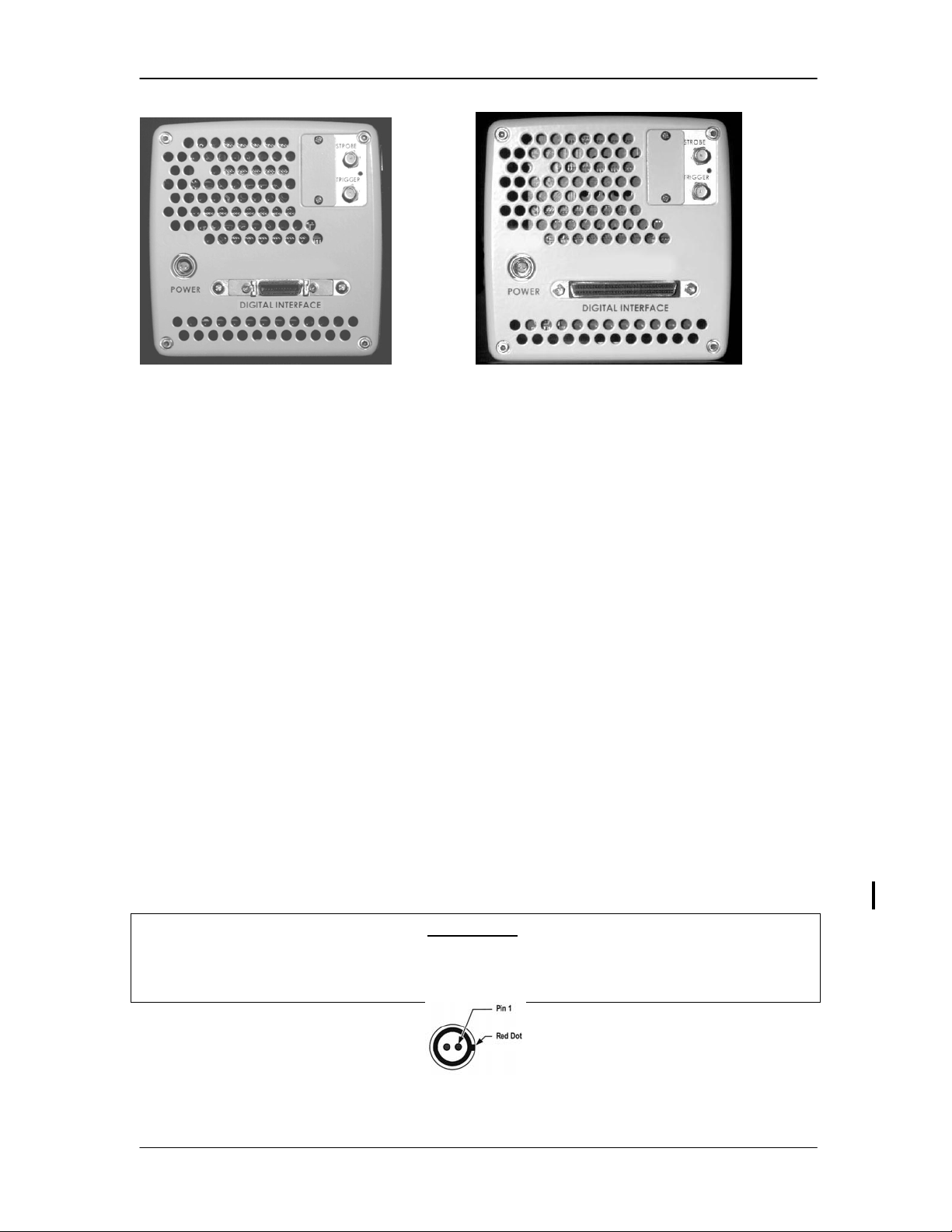
2.2 CAMERA REAR PANEL ...................................................................................................... 2-2
2.2.1 Digital Interface ....................................................................................................... 2-2
2.2.2 Trigger..................................................................................................................... 2-2
2.2.3 Strobe ..................................................................................................................... 2-2
2.2.4 DC Power Input....................................................................................................... 2-2
2.3 CABLES ........................................................................................................................... 2-3
2.4 HARDWARE SETUP ........................................................................................................... 2-4
2.5 ROUTINE MAINTENANCE ................................................................................................... 2-5
2.6 TECHNICAL SUPPORT/CONTACT INFORMATION .................................................................. 2-5
3. CAMERA OPERATION ........................................................................................................ 3-1
3.1 INTRODUCTION ................................................................................................................. 3-1
3.2 SERIAL INTERFACE PROTOCOL.......................................................................................... 3-1
3.3 ERROR CODES................................................................................................................. 3-2
3.4 CONTROL COMMANDS ...................................................................................................... 3-2
3.4.1 Readout Channels .................................................................................................. 3-2
3.4.2 Mode Control .......................................................................................................... 3-2
3.4.3 Continuous .............................................................................................................. 3-2
3.4.4 Continuous Fluoroscopy ......................................................................................... 3-3
3.4.5 Controlled................................................................................................................ 3-3
3.4.6 Trigger..................................................................................................................... 3-3
3.4.7 Double Exposure .................................................................................................... 3-3
3.4.8 Mode ....................................................................................................................... 3-4
3.4.9 Binning Selection .................................................................................................... 3-4
3.4.10 Frame Rate Set....................................................................................................... 3-4
3.4.11 Exposure ................................................................................................................. 3-5
3.4.12 Trigger..................................................................................................................... 3-5
3.4.13 Transfer Pulse Delay .............................................................................................. 3-6
3.4.14 Transfer Pulse Width .............................................................................................. 3-6
3.4.15 Pixel-by-Pixel Corrector .......................................................................................... 3-7
3.4.16 Digital Gain ............................................................................................................. 3-7
3.4.17 Gain Select ............................................................................................................. 3-7
3.4.18 Look Up Table......................................................................................................... 3-7
3.4.19 Alternate Correction Table...................................................................................... 3-8
3.4.20 Strobe Polarity ........................................................................................................ 3-8
3.4.21 Defect Conceal ....................................................................................................... 3-8
3.4.22 Save ........................................................................................................................ 3-8
3.4.23 Reset....................................................................................................................... 3-9
3.4.24 Display Wedge........................................................................................................ 3-9
3.4.25 Smear Correction.................................................................................................... 3-9
3.4.26 PSC Command ..................................................................................................... 3-10
3.4.27 Serial Communication Protocol ............................................................................ 3-10
3.4.28 Fast Read Mode ................................................................................................... 3-10
3.5 QUERY COMMANDS ........................................................................................................ 3-11
91000116-001 Revision B iv 10/15/02

MegaPlus®Model ES 4.0/E
3.5.1 Temperature Query............................................................................................... 3-11
3.5.2 Status Query ......................................................................................................... 3-11
3.5.3 Identification Query ............................................................................................... 3-11
3.6 ALPHABETICAL COMMAND SUMMARY............................................................................... 3-12
4. INTERFACE SPECIFICATIONS .......................................................................................... 4-1
4.1 INTRODUCTION ................................................................................................................. 4-1
4.2 DIGITAL INTERFACE CONNECTOR ...................................................................................... 4-1
4.3 CAMERA LINK CONNECTOR (OPTIONAL) ............................................................................ 4-1
4.4 DIGITAL VIDEO OUTPUTS .................................................................................................. 4-1
4.5 TIMING OUTPUTS.............................................................................................................. 4-1
4.6 CONTROL INPUTS ............................................................................................................. 4-1
4.7 TIMING WAVEFORMS ........................................................................................................ 4-5
4.8 SPECIFICATIONS............................................................................................................... 4-7
4.8.1 Video Performance ................................................................................................. 4-7
4.8.2 Camera Mechanical ................................................................................................ 4-7
4.8.3 Temperature ........................................................................................................... 4-7
4.8.4 Humidity .................................................................................................................. 4-7
4.9 C-MOUNT CAMERA DIMENSIONS ....................................................................................... 4-8
4.10 F-MOUNT CAMERA DIMENSIONS ..................................................................................... 4-10
APPENDIX A – ERROR CODES AND DESCRIPTIONS................................................................ I
LIST OF FIGURES
Figure 2-1. Camera Body Bottom................................................................................................. 2-1
Figure 2-2. C-Mount Lens Length Limit........................................................................................ 2-1
Figure 2-3A. Rear Panel (CameraLink) Figure 2-3B. Rear Panel (RS422/LVDS)................... 2-2
Figure 2-4. DC Power Connector Pins ......................................................................................... 2-2
Figure 2-5. ES 4.0/E Cable Types ................................................................................................2-3
Figure 2-6. Component Connection Diagram............................................................................... 2-4
Figure 3-1. Wedge Display Patterns............................................................................................. 3-9
Figure 4-1. Digital Interface Connector.........................................................................................4-2
Figure 4-2. Continuous Mode – Variable Exposure Timing .......................................................... 4-5
Figure 4-3. Continuous Mode – Variable Exposure Timing (With External Trigger Sync)............ 4-5
Figure 4-4. Triggered Mode Timing .............................................................................................. 4-5
Figure 4-6. Double Image Mode Timing ....................................................................................... 4-6
Figure 4-7. Controlled Mode Timing ............................................................................................. 4-6
Figure 4-8. Line Timing................................................................................................................. 4-6
Figure 4-9. C-Mount Camera Dimensions (Front and Bottom Views).......................................... 4-8
Figure 4-10. C-Mount Camera Dimensions (Side View) .............................................................. 4-9
Figure 4-11. F-Mount Camera Dimensions (Front and Bottom Views) ...................................... 4-10
Figure 4-12. F-Mount Camera Dimensions (Side View)..............................................................4-11
LIST OF TABLES
Table 4-1. Digital Interface Connector Pin Out (on rear of camera) ............................................. 4-2
Table 4-2. 68-Pin Interface Cable*, With 9-Pin RS232 Cable ...................................................... 4-3
Table 4-3. 26-Pin Camera Link Cable Pinout .............................................................................. 4-4
91000116-001 Revision B v USER’S MANUAL

REDLAKE MASD, INC.
THIS PAGE INTENTIONALLY LEFT BLANK
91000116-001 Revision B vi 10/15/02

MegaPlus®Model ES 4.0/E
1. INTRODUCTION
1.1 Introduction
With spatial resolution of four million pixels, and several different frame rates achieved through
binning, the Redlake MASD, Inc. MegaPlus Camera, Model ES 4.0/E, is designed for medical,
scientific, inspection, and machine vision applications. The compact camera package operates
through a digital connection to a host computer. The digital interface connector, located on the
camera’s rear panel, sends eight-bit digital output video to the computer and receives control
commands from the computer. This camera can be ordered with a twelve-bit digital video output
and/or a Camera Link interface as options.
Featuring an interline Charge Coupled Device (CCD) sensor array, the camera has
2048 (H) x 2048 (V) light sensitive elements (pixels). These pixels are 7.4 microns square with a
60% fill ratio. This MegaPlus camera model has individual gain and offset correction for each
pixel. Pixel by pixel gain and offset correction gives the camera a uniform flat field response at all
light levels.
The camera operates continuously or in one of three triggered modes. A minimum
programmable exposure time of 98 microseconds (98ms) is possible with the camera’s electronic
shutter. The frame rate is unaffected by the exposure time in continuous mode. The camera is
capable of binning and has dual output channels with data rates of 10, 20 or 40 MHz. In the
512 x 512 mode, the camera has a maximum frame rate of 60 fps. In the 1K x 1K binning mode,
the camera has a maximum frame rate of 30 fps. In the 2K x 2K binning mode, the camera has a
maximum frame rate of 15 fps at 40Mhz and 8 fps at 20Mhz. The camera requires a maximum of
24 watts at 24 volts DC and can be connected to commercially available frame grabber boards
capable of handling twelve bits of video data. Please note that some frame grabber boards may
not support the highest camera frame rates. Check with your frame grabber board manufacturer.
1.2 How to Use This Manual
WARNINGS, CAUTIONS and NOTES
As you read this manual, you will notice that some of the information is presented as a
WARNING, CAUTION or NOTE. It is important that you understand the significance of these
terms.
A WARNING is important to the safety of anyone operating the Camera and should not be
disregarded under any circumstances.
A CAUTION is intended to alert you to an operation or condition that may cause loss of data or
harm to your Camera.
A NOTE contains information that is important to the operation of your Camera.
Chapter 1 contains an explanation of this manual and a warranty statement.
Chapter 2 explains the function of the controls and connectors of the MegaPlus Camera.
Chapter 3 contains the commands used to operate the camera. The camera is remotely
operated by entering commands into a computer connected to the camera.
Chapter 4 details the signals carried by the digital interface connector, including timing
waveforms.
91000116-001 Revision B 1-1 USER’S MANUAL

REDLAKE MASD, INC.
LIMITED WARRANTY
For a period of one (1) year from the date of shipment, the Redlake Product and any Redlake
manufactured accessories (collectively the “Product”), shall perform substantially in accordance
with the material provisions of the user manual for the Product (“Limited Warranty”). If, because
of a defect in workmanship or material, the Redlake Product fails to perform in accordance with
the Limited Warranty, then, as the sole available remedy, Redlake shall repair or replace, at
Redlake’s option, the Redlake Product or any part thereof. The sole remedy of repair and
replacement is contingent upon shipment of the Product, within the Limited Warranty period, to
Redlake’s United States facility. Redlake shall have no obligation under this Limited Warranty to
provide local repair or replacement services for the Product, but will, at Redlake’s sole discretion,
provide repair and replacement service under the terms of the Limited Warranty at its non-United
States facilities upon prior written request of the Product Purchaser.
NOTE: THIS WARRANTY DOES NOT APPLY TO THE FOLLOWING CONDITIONS:
(1) damage caused by a failure to operate the Product in accordance with Redlake’s written
instructions, including, but not limited to, environmental specifications listed in the Redlake user
manual; (2) damage caused by accidental user damage, misuse or abuse of the Product; (3)
damage caused by the unauthorized attempted repair of or tampering with the Product by non-
Redlake personnel; or (4) damage resulting from shipping of the Product.
EXCEPT FOR THE LIMITED WARRANTY STATED IN THIS SECTION, REDLAKE DISCLAIMS
ANY AND ALL WARRANTIES, EXPRESS OR IMPLIED, INCLUDING BUT NOT LIMITED TO,
ANY WARRANTY OF MERCHANTABILITY, NON-INFRINGEMENT, OR FITNESS FOR A
PARTICULAR PURPOSE, REGARDING THE REDLAKE PRODUCT OR ANY PART THEREOF.
IN NO EVENT SHALL REDLAKE BE LIABLE FOR ANY INCIDENTAL, CONSEQUENTIAL OR
SPECIAL DAMAGES, INCLUDING WITHOUT LIMITATION LOSS OF BUSINESS OR
PROFITS, EVEN IF REDLAKE RECEIVES NOTICE IN ADVANCE THAT THESE KINDS OF
DAMAGES MIGHT RESULT, NOR SHALL REDLAKE’S AGGREGATE CUMULATIVE
LIABILITY TO THE PRODUCT PURCHASER, PRODUCT RECIPIENT, OR PRODUCT
CUSTOMER, PURSUANT TO ANY AND ALL CLAIMS AND LEGAL THEORIES (INCLUDING
NEGLIGENCE AND BREACH OF CONTRACT), EXCEED THE ORIGINAL COST OF THE
PRODUCT PAID TO REDLAKE BY THE ORIGINAL PURCHASER OF THE PRODUCT.
Redlake MASD, Inc. 11633 Sorrento Valley Road, San Diego, California 92121-1010
(Redlake, MegaPlus and 3M are trademarks.)
91000116-001 Revision B 1-2 10/15/02

MegaPlus®Model ES 4.0/E
2. CONTROLS AND CONNECTORS
2.1 Camera
NOTE: A lens cap is installed on each camera to keep dust from getting on the optical sensor or
components when it is shipped. Remove the lens cap and install your lens in a dust free
environment.
2.1.1 Mounting the Camera
The MegaPlus camera has two ¼-20 threaded screw holes for mounting purposes on the bottom
of the camera body (see Figure 2-1). There are two secondary holes, 0.23 inches (5.84 mm) in
diameter, to accommodate a locating pin. There are complete dimensional drawings at the end
of Chapter 4 of this manual.
Figure 2-1. Camera Body Bottom
2.1.2 Attaching the Lens
The camera can be purchased with either a C-mount or F-mount lens adapter. If your camera is
equipped with an F-mount lens adapter, insert the lens into the locking ring, then rotate the lens
counterclockwise until it clicks into position. To remove the lens, hold the release button down as
you rotate the lens clockwise.
If your camera is equipped with a C-mount lens adapter, screw the lens clockwise into the
adapter until you are no longer able to turn the lens with light pressure.
CAUTION: Some C-mount lenses may extend into the camera more than 0.20 inches
(5.08 mm), which may cause damage to internal optical components. Check the
dimension of any lens you plan to use as shown in Figure 2-2.
Figure 2-2. C-Mount Lens Length Limit
91000116-001 Revision B 2-1 USER’S MANUAL

REDLAKE MASD, INC.
Figure 2-3A. Rear Panel (CameraLink) Figure 2-3B. Rear Panel (RS422/LVDS)
2.2 Camera Rear Panel
2.2.1 Digital Interface
The Digital Interface is available as a 68-pin, high density, dual row, D type connector or, as a
purchased option, a 26-pin, high-density Camera Link connector that connects the camera to a
frame grabber board and a serial communication interface for camera control. The frame grabber
board processes and displays video from the camera. A complete technical description of the
connectors and the signals that they carry is contained in Chapter 4 of this manual.
2.2.2 Trigger
The TRIGGER coaxial SMA type input connector on the rear panel of the camera accepts CMOS
TTL signals with a threshold of approximately 2.5 volts. The trigger pulse should have duration of
at least 100 nanoseconds and should be transmitted to the camera using a coaxial cable
terminated at the camera. The camera synchronizes to an external event using this input. The
operator can set the camera to respond to a positive or negative going trigger signal. See the
timing waveforms in Chapter 4 of this manual.
2.2.3 Strobe
The STROBE coaxial SMA type connector on the rear panel of the camera outputs a signal that
is TTL compatible and can drive a 50-ohm load. The strobe output pulse should be transmitted
through a coaxial cable with a terminating resistor at the receiving end. The leading edge of this
output signal can be used to fire a strobe light. The output signal polarity is user-definable. See
the timing waveforms in Chapter 4 of this manual.
2.2.4 DC Power Input
The DC power input is a two-pin connector. The power supply voltage must be 24 volts DC,
±4 volts DC, measured at the camera’s power connector. The current draw is a maximum of
1.0 amp with a typical draw of 0.8 amps.
WARNING!
Reversing the polarity of the DC voltage input or applying voltage levels in excess of 30
volts may permanently damage the camera. Pin 1 must be positive with respect to the
other pin. Pin 1 is nearest the RED DOT on the connector ring. See Figure 2-4.
Figure 2-4. DC Power Connector Pins
91000116-001 Revision B 2-2 10/15/02

MegaPlus®Model ES 4.0/E
2.3 Cables
There are three different cables available to connect the MegaPlus Camera to your computer, as
shown in Figure 2-5 below. The cable needed to connect your camera to your frame grabber
depends upon the options you selected at purchase.
Figure 2-5. ES 4.0/E Cable Types
91000116-001 Revision B 2-3 USER’S MANUAL

REDLAKE MASD, INC.
2.4 Hardware Setup
Follow the instructions supplied by the frame grabber manufacturer when you are using their
cables to install your camera. If using Redlake supplied cables, connect the camera as shown in
Figure 2-6 below. Your equipment may vary from that illustrated below.
NOTE: Illustration is an approximation.
Your equipment may differ.
Figure 2-6. Component Connection Diagram
91000116-001 Revision B 2-4 10/15/02

MegaPlus®Model ES 4.0/E
2.5 Routine Maintenance
There are no user serviceable parts inside the camera. The camera must be returned to the
factory for repair if a malfunction occurs.
The lens and the sensor cover glass should only be cleaned using dust-free compressed air.
Clean the exterior of the camera with a soft, dry, lint-free cloth. For stubborn dirt, the cloth may
be dampened with a mild soap solution.
2.6 Technical Support/Contact Information
FOR TECHNICAL SUPPORT OR OTHER INFORMATION,
CONTACT US AT:
Telephone: 1-800-854-7006 (USA and Canada only)
Outside the USA: (858) 481-8182
Fax: (858) 350-9380
Internet: www.redlake.com
Mailing Address:
Redlake MASD, Inc., 11633 Sorrento Valley Road, San Diego, California 92121-1010
For international customers, please contact your authorized Redlake MASD, Inc. Distributor for
information. You may also contact one of the below listed service centers:
Roper Scientific BV (Europe, Middle East and Africa):
Telephone: (31) 347 32 4989
Fax: (31) 347 32 4979
Internet: subbink@roperscientific.com
Mailing Address:
Roper Scientific BV, Ir. D.S. Tuijnmanweg 10, 4131 PN Vianen, Nederland
Nippon Roper KK, Japan: (For Japan Only)
Telephone: (81) 3 5639 2770
Fax: (81) 3 5639 2775
Mailing Address:
Nippon Roper KK, 6F Sakurai Building, 2 8 19 Fukagawa Koto Ku, Tokyo, 135-0033,
Japan
91000116-001 Revision B 2-5 USER’S MANUAL

REDLAKE MASD, INC.
THIS PAGE INTENTIONALLY LEFT BLANK
91000116-001 Revision B 2-6 10/15/02

MegaPlus®Model ES 4.0/E
3. CAMERA OPERATION
3.1 Introduction
The MegaPlus camera, Model ES 4.0/E, does not have any manual controls on the camera itself.
Camera operation is accomplished by commands sent to the camera through a serial data link
from a personal computer (PC). The camera serial data link may be either RS232 or RS422. In
either case, the command syntax is the same.
The commands in this chapter are in the order that you would use to setup a camera for the first
time. A list of the camera functions, commands and appropriate page numbers follows:
NOTE: The commands can be entered in either upper or lower case.
NOTE: These same commands and their argument ranges are alphabetized and
summarized on page 3-12.
FUNCTION COMMAND PAGE
Readout Channels RDM 3-2
Mode Command MDE 3-4
Binning Set BNS 3-4
Frame Rate Set FRS 3-5
Exposure EXE 3-5
Trigger TRS, TRM, TRE 3-6
Transfer Pulse Delay TPD 3-6
Transfer Pulse Width TPW 3-7
Pixel by Pixel Corrector OGC 3-7
Digital Gain DGN 3-7
Gain Select GAS 3-7
Look Up Table LUT 3-7
Alternate Correction Table ACT 3-8
Strobe Polarity STP 3-8
Defect Conceal DEF 3-8
Save SAV 3-8
Reset RST 3-9
Display Wedge WDG 3-9
Smear Correction SMC 3-10
Serial Communication SCP 3-10
PSC Command PSC 3-10
Fast Read Mode FAS 3-10
Identification Query IDN 3-11
Status Query STS 3-11
Temperature Query TMP 3-11
3.2 Serial Interface Protocol
The camera uses a full duplex UART type asynchronous system, using standard nonreturn-to-
zero (NRZ) format (one start bit, eight data bits, one stop bit, no parity). The baud rate is fixed at
9600. The character code is ASCII standard.
The character flow control protocol is XON/XOFF. XON is assigned DC1 (control-Q) and XOFF
is assigned DC3 (control-S). The receiver sends the XOFF character when it wants the sender to
pause in sending data and an XON character when it wants the sender to resume.
91000116-001 Revision B 3-1 USER’S MANUAL

REDLAKE MASD, INC.
The camera will recognize a command as three command characters, followed by a space
character (or “?” in the case of a query), followed by an argument that consists of one or more
characters, ended by the carriage return and line feed characters. The camera responds to a
valid command with a carriage return and line feed (CR-LF).
3.3 Error Codes
The camera responds to an erroneous command or query by presenting the user with an error
code. The error codes and an explanation for each code are contained in Appendix A of this
manual.
3.4 Control Commands
NOTE: This section of the manual contains the commands and arguments in bold type. The
carriage return and line feed at the end of each command are not shown, as they are
required in every instance.
3.4.1 Readout Channels
Use this command to switch to single channel operation.
Suggestion: Set the camera frame rate to 8 fps (frames per second) using the FRS command
before changing the number of readout channels. Otherwise, the camera may change the frame
rate. See the valid frame rates versus readout channels listed on page 3.5 within the FRS
command description.
TYPE IN: RESPONSE EXPLANATION
RDM 1 CR-LF Sets the camera to single channel readout.
RDM 2 CR-LF Sets the camera to dual channel readout.
RDM? Queries the camera’s current readout.
RDM x Means the readout is set as indicated.
3.4.2 Mode Control
The MegaPlus camera operates in one of six modes: continuous, continuous fluoroscopy,
controlled, trigger, and double exposure. The mode of operation is selected by the MODE
command. The timing waveforms in Chapter Four may help you understand the different modes
of operation.
3.4.3 Continuous
The camera will take pictures at 15 fps in 2K x 2K binning mode, 30 fps in 1K x 1K binning mode,
and 60 fps in 512 x 512 mode. The camera can be synchronized to an external trigger source
through the TRIGGER input on the rear panel of the camera or the EXPOSE input of the digital
interface connector.
When multiple cameras are driven from the same trigger source, they will be synchronized to
each other within ±100 nanoseconds. The exposure time range is between 91 microseconds and
64.957 milliseconds in 2K x 2K binning mode. The exposure time range is between 92
microseconds and 32.451 microseconds in 1K x 1K binning mode. The exposure time range for
the 512 x 512 binning mode is approximately 98 microseconds to 16.2 milliseconds.
91000116-001 Revision B 3-2 10/15/02

MegaPlus®Model ES 4.0/E
3.4.4 Continuous Fluoroscopy
This mode is similar to the Continuous mode, except that the electronic shutter is not used. The
exposure time in continuous fluoroscopy mode is equal to the frame rate time. A frame rate of 30
fps means that the exposure time is 33.3 milliseconds. Since the exposure is fixed, the software
control of exposure is disabled in this mode.
3.4.5 Controlled
The start and exposure time of each image is controlled by input signals supplied by the user to
the EXPOSE input pins in the digital interface connector or the trigger input on the rear panel of
the camera. The exposure time is equal to the time the EXPOSE input signal is true. The frame
rate is inversely proportional to the exposure plus the readout time. The exposure time is
unlimited, but at room temperatures, dark field nonuniformities become noticeable with exposure
times greater than 100 milliseconds.
3.4.6 Trigger
Each exposure is started by a signal connected to the EXPOSE input pins of the digital interface
connector or the trigger input on the rear panel of the camera. The exposure command sets the
exposure time. An exposure starts 17 microseconds (± 100 nanoseconds) after the active edge
of the trigger pulse and ends at the exposure time selected by the EXE command. Use the TRM
command to select the positive or negative edge of the trigger pulse as the trigger point.
The EXPOSE input sets the start time for each frame of video. The camera will ignore additional
EXPOSE signals until it completes the current exposure. The trigger mode of operation is used
to capture a single image or a sequence of images.
3.4.7 Double Exposure
The double exposure sequence begins after receiving a trigger input through the digital connector
or the TRIGGER connector on the rear panel of the camera. The camera captures the first image
in the photo diode array, and then transfers this image to the CCD array. The first image is
transferred from the CCD to the internal frame store while the second image is being captured by
the photo diode array. The second image is then transferred into the CCD array and from there
to the internal frame store’s second image buffer.
When operating in Double Exposure mode, the maximum frame rate is approximately 11.4 fps
due to the necessity for 2 frames per trigger. The camera will ignore triggers that it cannot
accept; so more than 5.7 triggers per second will result in slower operation. If the trigger rate is
set lower, the camera will track the trigger rate exactly.
91000116-001 Revision B 3-3 USER’S MANUAL

REDLAKE MASD, INC.
3.4.8 Mode
Use this command to set the camera mode of operation.
TYPE IN: RESPONSE EXPLANATION
MDE CS CR-LF Sets the mode to continuous.
MDE CD CR-LF Sets the mode to controlled.
MDE TR CR-LF Sets the mode to trigger.
MDE DE CR-LF Sets the mode to double exposure.
MDE CF CR-LF Sets the mode to continuous fluoroscopy.
MDE? Queries the current mode setting.
MDE xx Means the mode is set as indicated.
3.4.9 Binning Selection
Binning gives you the option of trading resolution for increased frame rate and better signal to
noise ratio. Binning is the process of grouping adjacent pixels electronically; thereby reducing the
time required to readout an image. This camera can group two adjacent pixels horizontally and
vertically giving one quarter the resolution but twice the frame rate with a better signal to noise
ratio.
TYPE IN: RESPONSE EXPLANATION
BNS 1 CR-LF No binning is performed; resolution is 2K x 2K pixels.
BNS 2 CR-LF 2 horizontal and 2 vertical pixels are binned together
producing an effective resolution of 1K x 1K pixels.
BNS 3 CR-LF 4 horizontal and 4 vertical pixels are binned together
producing an effective resolution of 512 x 512 pixels.
BNS? Queries the current binning selection.
BNS x Means the binning selection is set as indicated.
NOTE: Check the camera’s frame rate setting after changing the binning setting. Changing the
binning setting may cause the frame rate to change to the nearest valid setting.
3.4.10 Frame Rate Set
This command sets the camera’s frame rate dimensioned in frames per second (fps). Some
frame rates are only valid in specific combinations of readout channels, selected with the RDM
command, and binning modes, selected with the BNS command.
If you change the binning mode the camera will switch to the nearest valid frame rate.
NOTE: The FRS command sets the maximum frame rate limit in controlled and continuous
modes. FRS must be set to 15 in double exposure mode.
91000116-001 Revision B 3-4 10/15/02

MegaPlus®Model ES 4.0/E
TYPE
IN
RESPONSE
RDM=2
BNS=3
RDM=2
BNS=2
RDM=2
BNS=1
RDM=1
BNS=3
RDM=1
BNS=2
RDM=1
BNS=1
FRS 60 CR-LF 60 fps/
20 MHz
** ** ** ** **
FRS 30 CR-LF 30 fps/
20 MHz
30 fps/
20 MHz
** 30 fps/
20 MHz
** **
FRS 15 CR-LF 15 fps/
10 MHz
15 fps/
20 MHz
15 fps/
40 MHz
15 fps/
20 MHz
15 fps/
20 MHz
**
FRS 8 CR-LF ** 8 fps/
10 MHz
8 fps/
20 MHz
** 8 fps/
20 MHz
8 fps/
40 MHz
FRS 4 CR-LF ** ** 4 fps/
10 MHz
** ** 4 fps/
20 MHz
3.4.11 Exposure
This command sets the camera exposure time in increments of 0.063 milliseconds. In continuous
mode, the camera accepts exposure values from .091 to 64.957 milliseconds when BNS is set
to 1; and values between .092 and 32.451 milliseconds when BNS is set to 2. If the camera is
operating in triggered mode, the maximum exposure time becomes 112.298 milliseconds.
NOTE: The camera accepts and remembers a different exposure time for each of the three
binning modes. The camera switches to the stored exposure time when switching
binning modes.
TYPE IN: RESPONSE EXPLANATION
EXE xxxx CR-LF The argument range is from .091 to 112 to 298
milliseconds in increments of .063 milliseconds,
depending on the operating mode, the camera will
round up to the next valid setting for any exposure
value entered.
EXE? Queries the current exposure setting. The value
returned is the corrected value in milliseconds.
EXE xxxx Means the exposure is set, expressed in
milliseconds.
NOTE: After EXExxxx or EXE? Has been executed, type in “+” to increase the exposure time or
type in “-“ to decrease the exposure time by 0.063 milliseconds. The camera will respond
with the new value.
3.4.12 Trigger
This command selects the trigger source and polarity. There is two trigger inputs: the SMA
connector on the rear panel of the camera (labeled TRIGGER), and the EXPOSE input carried by
the digital interface connector. The camera will only respond to the selected source.
TYPE IN: RESPONSE EXPLANATION
TRS AIA CR-LF Selects the digital interface connector EXPOSE
signal as the trigger source.
TRS EXT CR-LF Selects the TRIGGER connector on the rear panel
as the trigger source.
TRS SW CR-LF Selects the TRE software commands as the trigger
source.
TRS? Queries the trigger source.
91000116-001 Revision B 3-5 USER’S MANUAL

REDLAKE MASD, INC.
TRM P
(see *NOTE)
CR-LF A positive going edge at the AIA EXPOSE input
trigger connector will start an exposure.
TRM N
(See *NOTE)
CR-LF A negative going edge at the AIA EXPOSE input or
the trigger connector will start an exposure.
TRM? Queries the current EXPOSE polarity.
TRE 0 CR-LF Ends an exposure in controlled mode if TRS SW is
in effect.
TRE 1 CR-LF Starts an exposure in all modes if TRS SW is in
effect.
TRE? Queries current state of trigger command.
*NOTE: The commands TRM and TRP are interchangeable. TRP may be used in place of TRM.
3.4.13 Transfer Pulse Delay
This command only applies to the double exposure mode. Transfer pulse delay sets the
exposure time for the first image. The exposure time for the second image is 64.946 milliseconds
in 2K x 2K mode, and 32.495 milliseconds with binning set to 1K x 1K.
TYPE IN: RESPONSE EXPLANATION
TPD xxx CR-LF Sets the delay in increments of 0.2 microseconds.
The argument range is from 1 to 999 microseconds.
If TPD is set to zero, the EXE value controls the
first image exposure time permitting equal exposure
time for both images.
TPD? Queries the current transfer pulse delay time
setting.
TPD xxx Means the time is set as indicated.
NOTE: After TPD xxx or TPD? has been executed, type in “+” to increase the transfer pulse
delay time or type in “-“ to decrease the delay time. The camera will respond with the new
value.
Sample commands with arguments:
TPD 1.6 Sets the delay time to 1.6 microseconds.
TPD 0 The EXE value now sets the delay time.
TPD 999 Sets the delay time to 999 microseconds.
3.4.14 Transfer Pulse Width
The transfer pulse width is fixed at twelve microseconds, except in double exposure mode. This
command sets the duration of the transfer pulse when the camera is in double exposure mode.
The transfer pulse width is the time that the first image has to transfer from the photo diode array
to the CCD array. As the transfer pulse width becomes shorter, the charge transfer between the
arrays does not have time to be completed and image quality will suffer.
TYPE IN: RESPONSE EXPLANATION
TPW xx CR-LF Sets the delay in increments of one microsecond.
The argument range is from 1 to 10 microseconds.
The default value is 8.
TPW? Queries the current transfer pulse width setting.
TPW xx Means the pulse width is set as indicated.
91000116-001 Revision B 3-6 10/15/02
Table of contents
Other Redlake MASD Security Camera manuals
Popular Security Camera manuals by other brands

Stealth Cam
Stealth Cam STC-U840IR instruction manual

Hamamatsu Photonics
Hamamatsu Photonics C9300-201 instruction manual

Siemens
Siemens CFFC1310-LP instruction manual

Panasonic
Panasonic Super Dynamic III WV-CW380 Brochure & specs

Dahua
Dahua HDW3441T-ZAS quick start guide

Axis
Axis M4206-V installation guide

American Dynamics
American Dynamics ADCDW Series datasheet

Mobi Technologies
Mobi Technologies MobiCam HDX Series quick start guide

Honeywell
Honeywell NEXPTZ4520HD-NET installation manual

Bosch
Bosch AUTODOME IP starlight 5000i installation manual

Panasonic
Panasonic WVCP220 - COLOR CCTV CAMERA operating instructions

Edimax
Edimax PT-31E Quick installation guide