Redline RL-101M User manual

1
10350 STATE HWY 30 College Station, TX 7784 (979) 776-7200
rev. 3
RL-101M Installation and Operation Manual
Re
SAFETY MESSAGE
•It is important to follow all instructions in this manual.
•This device is to be installed by a trained professional
who is familiar with Redline Safety products.
•Read and understand all instructions before installation
or use of this equipment
•Keep cover tight when circuits are alive.
•Test Instrument regularly to ensure it is operating
properly. After installation provide a copy of manual to
authorized personnel
IMPORTANT SAFETY WARNING
Failure to follow all safety and operational instructions
may result in property damage, serious injury or death.
Power Consumption and Voltage rating
RL101M instrument is powered by 6 AA batteries
(9VDC) internally.
1mA continuous consumption when the device is
operational.
Head Housing Certifications
NORTH AMERICAN CERTIFICATIONS (standard)
CLASS I, DIV 1 GROUP BCD , CLASS II GROUP EFG, CLASS III
CLASS I ZONE 1 AEx d IIC, Ex d IIC (Canada) ,NEMA TYPE 4X
RL-SSH Sensor Housing Certifications
CI, D1 BCD C1, Zn 1, IIB+H2, IIB, IIA

2
OPERATIONS OVERVIEW
Modes
1. Normal Operation
2. “NUL”
3. Calibrate
4. Assign Head Address
5. Set Background Gas Level
6. Check Battery Voltage
7. Err msg
8. Revision
9. Relay Test
10. Radio Signal Strength Input
11. OFF
12. Startup
13. “2HI”

3
Basic Operation
There are three main modes for the RL101M LEL sensor head Unit. In addition, there is an OFF
mode and a Startup mode. When the unit is powered there is a 30 second
(Startup) countdown during which some system values are displayed before going into the
Normal Operating mode. The Rl101M offers reed switches which allow unobtrusive calibration, meaning
you do not need to remove the Lid to the Rl101M. The reeds switch acts as a button with the redline
magnet. When the magnet is placed close to the reed it engages like a button, when the magnet is taken
away it disengages. Move the magnet repeatedly toward and away from the reed to change digits.
To get to the second mode this is addressing, press TEST once. To enter the third Mode, press TEST
again while in the 2nd Mode. Pressing TEST while in the 3rd Mode will get back into the 2nd mode or
addressing. Pressing MENU multiple times will get back to Normal Operating mode.
If left in any mode (except OFF), the unit will return to Normal Mode after three minutes.
When the Head unit changes modes, it will send a message to the Monitor. The display shows the ppm
in percentage, therefore 50 ppm would be would be displayed as 2.5 % (5%=100ppm) *Before use
allow 10 minutes for sensor warm up.*
Up and down buttons
Menu Reed Switch
Test Reed Switch
4 socket connecter from
LEL sensor housing
9VDC IN
XBEE 2.4G

4
1. Normal Operation
The RL101M Head unit monitors the LEL gas level. If the gas level is greater than or equal to the
background setting, the unit will send a message every 5 seconds; if less than the background setting,
the unit will send a message every 5 minutes. When the RL101M is in normal mode, 0.00 will show on
the display.
2. NUL
To place the RL101M into NUL Mode press Menu once. "nuL" will flash on the display. The RL101M
Head unit will monitor the gas level but will not send messages when in NUL Mode. NUL Mode is used
for removing any errors in the amplifiers that may cause a gas reading when there is no gas. Use the Up
button once to automatically adjust the readings to zero.
Use Up button or reed switch and
it will automatically adjust
readings to zero

5
3. Calibration
Before calibration, allow ten minutes for the senor to warm up. To place the Rl101M into CAL Mode,
press the MENU button twice. "cAL" will flash on the display. The RL102m Head unit monitors the gas
level but does not send messages to the monitor when in CALIBRATION mode.When calibration gas is
applied, the unit will display the reading. Use the up button when the gas reaches 2.5%. The RL 101M
should automatically calibrate the sensor to 2.5 % which equals the calibration gas; the monitor should
display 50 ( 5% = 100ppm). Pressing MENU will place the unit in Normal Operation and will begin
sending messages to the monitor.
4. Assign Radio (Head) to Channel
To access to this feature press TEST once. "Adr" will flash on the display when in that mode.
Use the UP and Down buttons to adjust the Address of the Head unit. There must be a corresponding
address set in the Monitor.
Press MENU button twice
or reed switch to place
RL101M in “cAL” mode
Use the Up button to
automatically calibrate the
sensor to 2.5 %

6
5. Set Background Gas Level
To access to this feature press TEST once, then MENU once. "brd" will flash on the display when in
Background Level mode (default setting is 7). Use the Up and Down buttons to adjust the Background
level.
When the gas level is equal to or greater than this number, the unit will transmit a message every 5
seconds; if less than this setting, the unit transmits every 5 minutes.
6. Check Battery Voltage
This mode displays the condition of the batteries. To access to this feature press TEST once, then MENU
twice "bat" will flash on the display when in this mode.
7. Error msg
If the display is showing “Err” that typically means the sensor housing is not connected or an LEL sensor
is not placed inside the sensor housing.
8. Revision
This mode shows the revision of the software that is being used in theRl101M Head unit. To access,
press TEST Twice. “R 2.3” should show on the display.
9. Relay Test
To enter this mode, press TEST twice and MENU once. “rEL’ should show display. Use the Up and Down
buttons to adjust the PPM value to send in a message to the Monitor.
The Monitor treats this PPM value in the same way it would treat an actual gas reading.
This will allow for the relays in the Monitor to be activated and shows that the Head unit
is communicating with the Monitor.

7
10. Radio Signal Strength Input
To enter into this mode press TEST twice and MENU once. "rIn" will flash on the display. This
mode allows the Head unit and Monitor to exchange messages. The monitor knows that the Head unit is
in this mode and resends the message. The Head unit stays awake in order to receive this resent
message. The Head unit measures the strength of the signal and displays it (the maximum Value is 255);
the units should work properly until the signal level drops to about 50. (Caution: since the radio stays
awake for this test, the battery is being discharged much faster in this mode. Try to spend as little time
in this test as possible.)
The Head unit transmits a message once per second and the Monitor responds immediately, so the test
must be performed for at least one second. The Head unit can be moved away from obstructions, up or
down or pointed to get the best reading. When the MENU button is pressed to leave this mode, the last
reading taken will be stored in memory; the stored reading will be included in the messages to the
monitor, so this reading can be examined at the Monitor. If no Monitor is in range, the readings will be
very low or zero. "rIn" will flash in the display.
11. OFF
To put the Head unit in the OFF mode, press the TEST button for about 4 seconds. The display
will show "OFF". This mode disables all transmissions by the Head unit. The unit will transmit a message
every 5 minutes with no gas present or every 5 seconds when the gas level is equal to or greater than
the background setting. To reduce the battery discharge, the unit can be set in OFF mode, where it will
never transmit. To wake the Head unit, press MENU, Up or TEST, and the unit will begin the startup
sequence.
12. Startup
When the RL101M is powered, it will display several values, like address and battery voltage, then the
unit will count up to 30 seconds and go into normal operation.
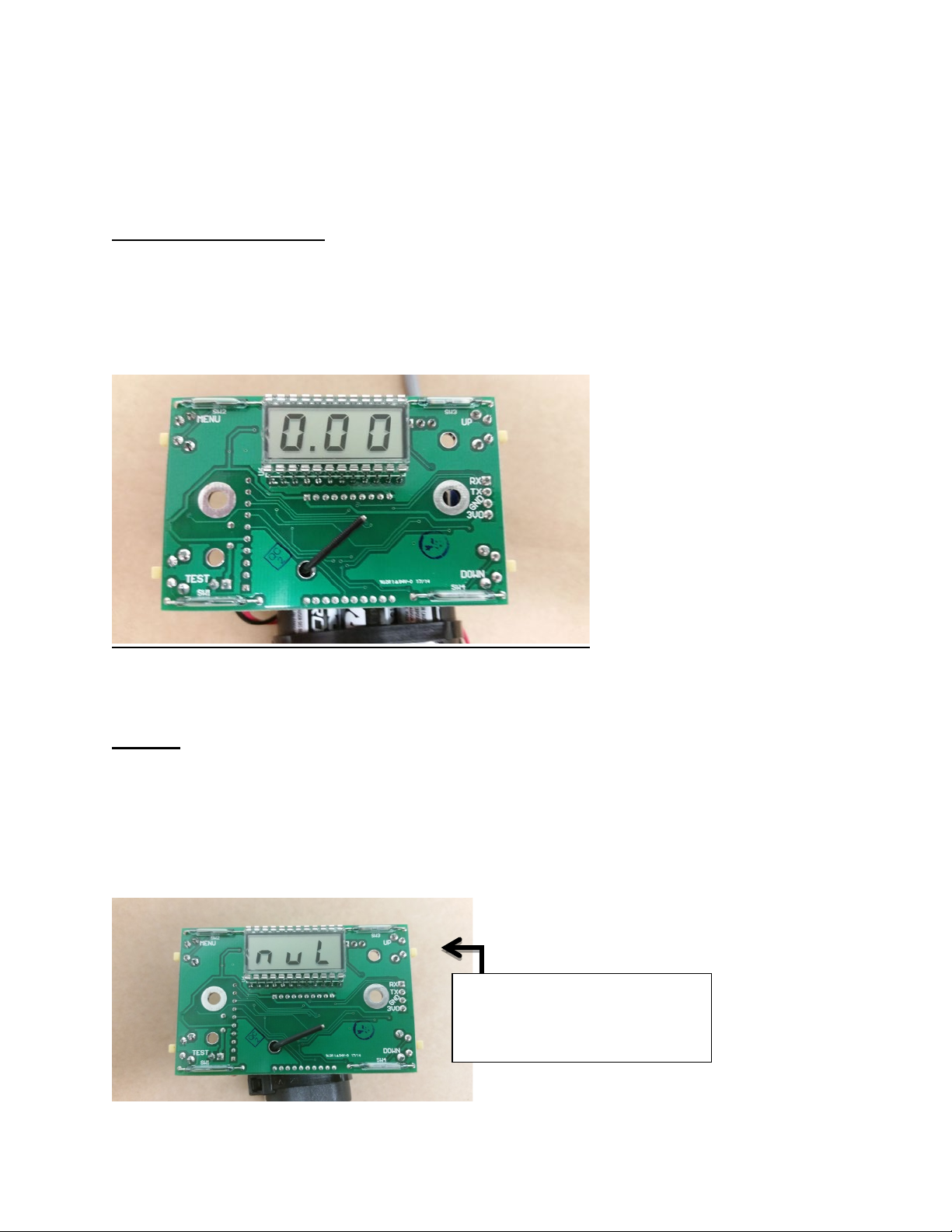
13. “2HI”
If the RL 101M displays the reading “2HI” in normal operating mode, that means the gas level has
earthier exceeded 5% or the sensor needs to be zeroed. To zero, put the RL102M in “nUL” mode press
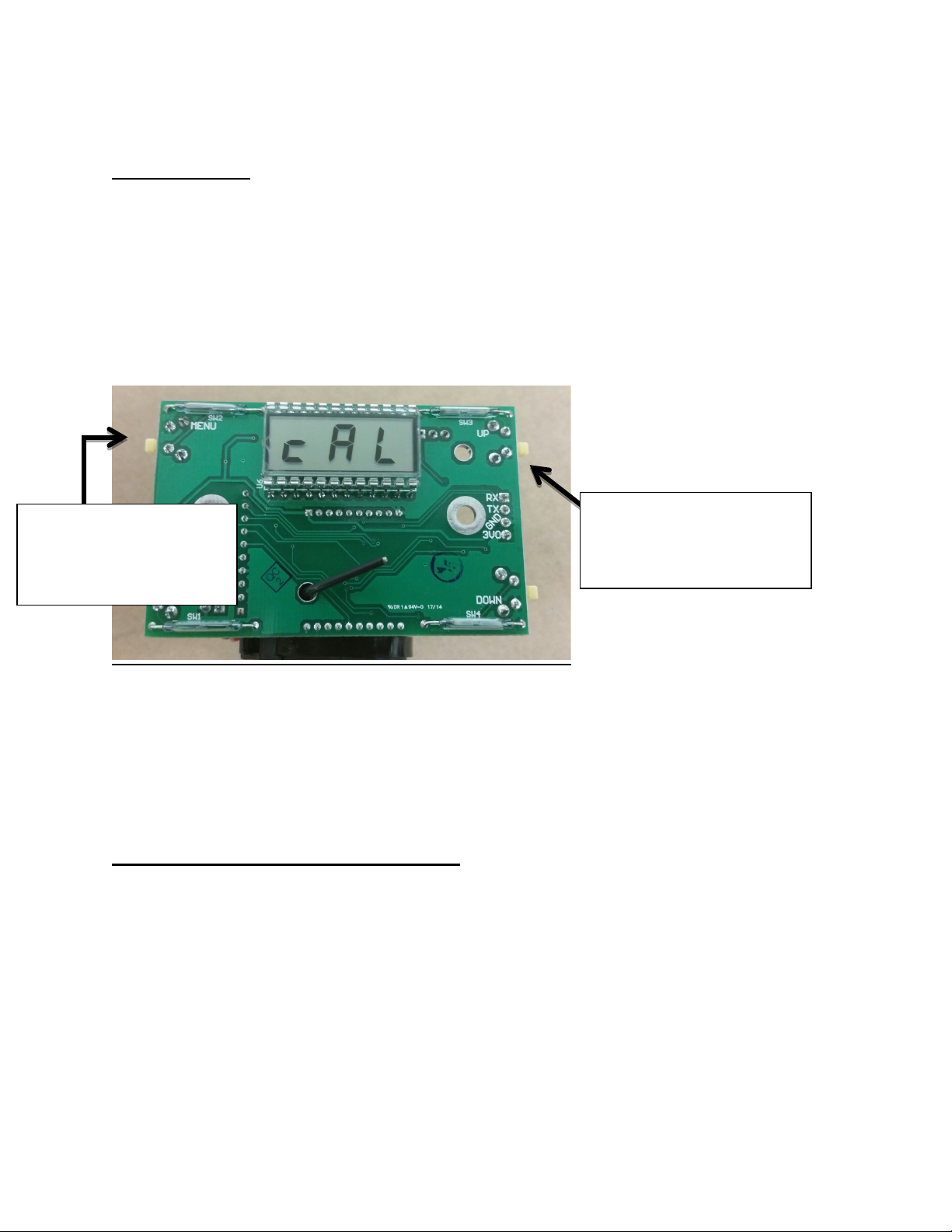
the up button and it will automatically adjust the reading to zero. Then calibrate.
For calibration see (# 3 in basic operations).

8
INSTALLATION
Important- before you install the Rl101M LEL sensor head make sure you have read the basic
operations to ensure proper understanding of the product. Also check battery voltage to ensure Rl102M
will function properly.
When installing the Rl101M LEL sensor head make sure to calibrate the sensor head. Put the Head into
“cal” mode. When LEL calibration gas is applied, the unit will display the reading. Use the Up button
when the gas is 2.5% and it will automatically calibrate the sensor. For calibration see Operations
overview (# 3 )
The Rl101M Head may be mounted at a customer specified height with the sensor housing pointed
down towards the ground. For best signal strength position the glass window in line of sight of the
Redline Monitor, also make sure there are no metal/nonmetal obstructions so signal will not be blocked.
MAINTENANCE
Redline Instruments recommends you check battery voltage every 90 days and Calibration of the head
every 30 days. Recommended battery replacement at 7.5VDC or lower, if battery is at 5.3VDC there will
not be sufficient power to transmit a signal. If your instrument is in need of repair you may send your
instrument to any of the redline location for repair. See website for location addresses. For
troubleshooting tips call (979)776-7200.
This manual suits for next models
1
Table of contents
Other Redline Accessories manuals
Popular Accessories manuals by other brands

Summit Treestands
Summit Treestands Outlook SU82083 manual

Wavion
Wavion WBS-2400 SCT 120 installation guide

Advance acoustic
Advance acoustic AXESS 3 AIR user manual

ZPE
ZPE ZPE-AIR-U01 Quick install guide

Blue Technix
Blue Technix Argos 3D-P320 quick start guide

Astro Shop
Astro Shop GSTAR-EX Quick reference guide