Redvision RVIP Series User manual

X-IP-SERIES
X-IP-SERIES USER MANUAL
Products Covered:
RVIP-SERIES PTZ Positioning Camera
RVIP-PSU Power Supply
RVIP-PSU-ALM16 Power Supply with Alarm Module
RVIP-PSU-ALM16-W PSU with Wireless PIR module
[RVIP v1.2]
©2015 Redvision CCTV Limited. All rights reserved.

1INSTALLING THE CAMERA HEAD
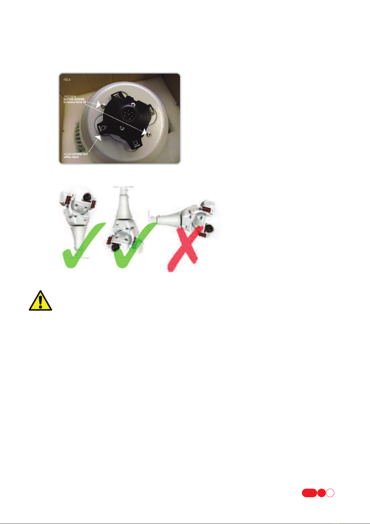
1.1 PTZ CONFIGURATION – CONVERTING BALL CAMERA TO DOME CAMERA 1
1.2 ATTACHING CAMERA TO BRACKET 1
1.3 BRACKET TYPES 2
1.4 HOW TO CANTILEVER ARMS FORWARD 2
2HOW TO CONFIGURE THE CAMERA 2
3POWER SUPPLY INSTALLATION & SETUP 3
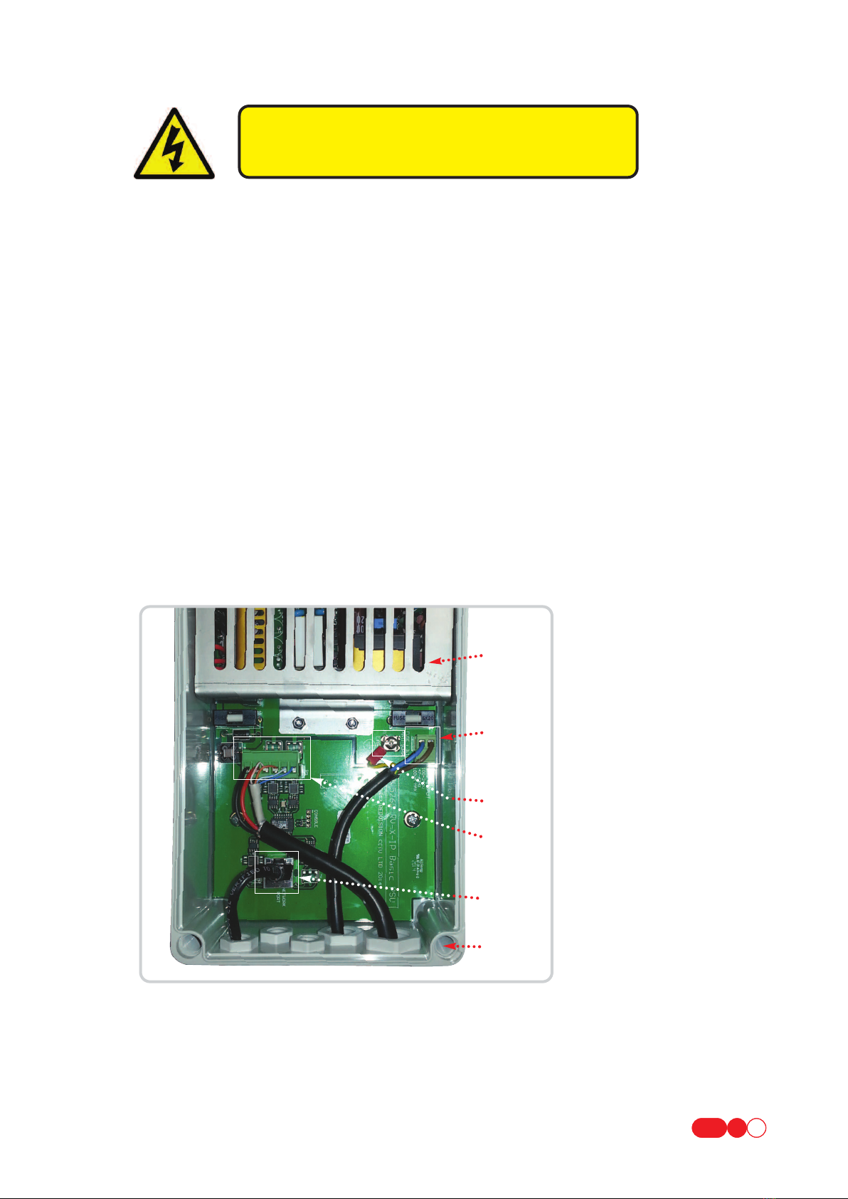
3.1 REDVISION IP POWER SUPPLY (RVIP-PSU) 4
3.1.1 SUPPLY VOLTAGE 4
3.1.1.1 INPUT VOLTAGE 4
3.1.1.2 OUTPUT VOLTAGE 4
3.1.2 RVIP-PSU INTERNAL CONNECTIONS 4
3.1.2.1 MAINS POWER INPUT 4
3.1.2.2 CAMERA CONNECTION 5
3.1.2.3 NETWORK CONNECTION 5
3.1.3 FUSE PROTECTION 5
3.2 REDVISION IP POWER SUPPLY WITH ALARM MODULE (RVIP-PSU-ALM) 6
3.2.1 SUPPLY VOLTAGE 6
3.2.1.1 INPUT VOLTAGE 6
3.2.1.2 OUTPUT VOLTAGE 6
3.2.2 RVIP-PSU-ALM INTERNAL CONNECTIONS 6
3.2.2.1 MAINS POWER INPUT 6
3.2.2.2 CAMERA CONNECTION 6
3.2.2.3 NETWORK CONNECTION 7
3.2.2.4 ALARM INPUTS 7
3.2.2.5 AUXILIARY OUTPUTS 7
3.2.3 FUSE PROTECTION 8
3.2.4 ALARM CONFIGURATION SWITCH SETTINGS 8
3.3 WIRELESS ALARM PSU (RVIP-PSU-ALM-W) 8
3.3.1 RVIP-PSU-ALM-W INTERNAL CONNECTIONS (ADDITIONAL) 9
3.3.1.1 ANTENNA CONNECTOR 9
3.3.2 CONFIGURING WIRELESS ALARM MODULE 9
3.3.2.1 DIP SWITCH SETTINGS 9
3.3.2.2 AERIAL 9
3.3.2.2.1 POSITIONING OF RVIP-PSU-ALM16-W 9
3.3.2.2.2 RETRO FITTING WIRELESS ALARM RECEIVER 9
4CAMERA SETUP 10
4.1 CONNECTING TO THE CAMERA 10
4.1.1 DIRECT CABLE CONNECTION 10
4.1.2 LAN CONNECTION USING LOCAL NETWORK WITH DHCP SERVER. 10
4.1.3 LAN CONNECTION WITHOUT LOCAL DHCP SERVER 11
4.1.4 DIRECT CABLE CONNECTION WITH DHCP 11
4.2 CAMERA CONFIGURATION VIA WEB INTERFACE 11
4.3 USER ACCOUNT CONFIGURATION 12
5CAMERA OPERATION
5.1 OPERATION VIA WEB INTERFACE 12
5.2 OPERATION VIA CGI COMMAND 12
5.3 OPERATION VIA ONVIF INTERFACE. 12
Table of Contents
X-IP-SERIES USER MANUAL

X-IP-SERIES USER MANUAL
6WEB INTERFACE 13
6.1 HOME 13
6.1.1 CAMERA 13
6.1.1.1 VIEW CAMERA 13
6.1.1.1.1 LIVE STREAMING 13
6.1.1.1.1.1 STREAMING OFF 13
6.1.1.1.1.2 PLAY STREAM 1 13
6.1.1.1.1.3 PLAY STREAM 2 13
6.1.1.1.1.4 PLAY STREAM 3 13
6.1.1.1.2 CONTROLS POPUP 14
6.2 PRESET POSITIONS 14
6.2.1 EDIT PRESETS 14
6.3 PATROL TOURS 14
6.3.1 RUN/STOP TOUR 14
6.3.2 EDIT TOUR 14
6.3.2.1 NAME 14
6.3.2.2 AUTO-POPULATE TOUR LIST 14
6.3.2.3 SPEED 14
6.3.2.4 DWELL 14
6.3.2.5 ORDER 14
6.3.2.6 TOUR LIST 14
6.4 ALARMS 15
6.4.1 VIEW ALARMS 15
6.4.1.1 LIVE ALARMS 15
6.4.1.2 UPDATE INTERVAL 15
6.4.2 CONFIGURE ALARMS 15
6.4.2.1 ALARM BOARD 15
6.4.2.2 WIRELESS ALARMS 15
6.5 CONFIGURE CAMERA 15
6.5.1 BASIC CONFIG 15
6.5.1.1 CAMERA TITLE 15
6.5.1.2 MOUNTING ORIENTATION 15
6.5.1.3 INSTALLATION NOTES 15
6.5.1.4 TIME & DATE SETTING 15
6.5.2 CAMERA PROFILES 16
6.5.2.1 RESTORE/HOME POSITION 16
6.5.2.2 CONTROL CONFIGURATION 16
6.5.2.3 SHORTCUTS 16
6.5.2.3.1 CAMERA PROFILE OVERRIDE 16
6.6 CAMERA PROFILES 17
6.6.1 BASE FEATURES 17
6.6.1.1 CAMERA PROFILE 17
6.6.1.2 VIDEO STREAMING PROFILES 18
6.6.2 ADMIN FUNCTIONS 18
6.6.2.1 NETWORKING CONFIGURATION 18
6.6.2.2 USER ACCOUNTS & PERMISSIONS 18
6.6.2.2.1 ADD USERS 18
6.6.2.2.2 EDIT/REMOVE USERS 18
6.6.2.3 MAINTENANCE 18
6.6.2.3.1 REBOOT CAMERA 18
6.6.2.3.2 RESET ONVIF PROFILES 18
6.6.2.3.3 RUN DATUM NOW 19
6.6.2.3.4 RESET TO DEFAULTS 19
6.6.2.3.5 FIRMWARE UPGRADE 19

X-IP-SERIES USER MANUAL
7WEB BROWSER CONFIGURATION 20
7.1 JAVASCRIPT 20
7.2 VIDEO STREAMING PLUGIN 20
8TECHNICAL SPECIFICATION 22
9WARRANTY INFORMATION 23

OBSERVE THE FOLLOWING PRECAUTIONS WHEN INSTALLING:
1. Mount the Camera in a position where it cannot be be interfered with either intentionally or accidentally.
2. The mounting surface should be capable of supporting the weight of both the Camera and mounting brackets under
all expected conditions of load, vibration and temperature.
3. The mounting brackets should be fitted in accordance with instructions and should observe all appropriate safety
precautions & local building regulations.
4. Ensure the Camera is in the correct orientation, see FIG B above.
X-IP-SERIES USER MANUAL
1
1INSTALLING THE CAMERA HEAD
1.1 PTZ CONFIGURATION – CONVERTING BALL CAMERA TO DOME CAMERA
The RVX Series can be mounted as a dome or ball PTZ configuration. To convert the dome to ball PTZ remove the M4
button head screws with 2.5mm allen key provided. See FIG A below.
1.2 ATTACHING CAMERA TO BRACKET
BRACKET INSTALLATION:
Fixings to the various bracket types will depend on the fixing surface. It is important to use adequate quality fixings to
safely support the complete Dome/Ball PTZ assembly. Fixing slots on a 4” PCD provide adequate clearance for 6mm
bolts if attaching the Pedestal or Swan Mount to the mast.
FLYING LEAD:
If using a Swan/Pedestal/Pendant Mount, install the Fly Lead optionally through the Central Mounting Tube or via a
20mm Gland Entry Point. The Gland Entry is supplied with a 20 x 1mm thread to accomodate industry standard
20mm Glands.
FIG B MOUNTING ORIENTATION

X-IP-SERIES USER MANUAL
2
TECH SUPPORT COMMENT: It is important to configure software settings to the camera orientation
(Basic Configuration > Mounting Orientation) i.e. is the Camera hanging down or upright?
‘hanging down’ would be using one of the following bracket types :
•swan [RVIP-SWAN] ,
•pendant [RVIP-PNDT]
•or wall [RVIP-WALL] - NOT SUITABLE FOR UPRIGHT MOUNTING
‘Upright’ would be using the pedestal bracket [RVIP-PED]
ATTACHING CAMERA TO THE BRACKET: See Fig C & D below
1. Remove Mount Cover Plate.
2. Fully unscrew Hand Lock Nut.
3. Offer Camera to Bracket. The Mounting Boss orientation is important and should match the picture in FIG C & D below.
i.e The Flat Edge should be positioned to the rear and the Retaining Lugs engaged in the Boss Cut Outs.
4. If RVIP-PED (Pedestal) is being used support the Camera with hand when tightening the Hand Lock Nut - ensure the
Hand Lock Nut is fully tightened.
5. Ensure the Clearance is even throughout 360° rotation and the Camera is free moving.
6. Replace Mount Cover Plates.
1.3 BRACKET TYPES
RVIP-SWAN (Swan mount), RVIP-WALL (Wall mount), RVIP-PNDT (Pendant mount), RVIP-PED (Pedestal for mast/tower mount).
1.4 HOW TO CANTILEVER ARMS FORWARD
1. Remove pear shaped badge on each arm using small flat head screw driver.
2. Slightly loosen by one turn (BUT DO NOT REMOVE) the allen screws.
3. Cantilever the Ball Arms forward to ‘STOP’ position.
4. Tighten allen screws.
5. Replace badges (spares are provided).
6. See Section 6.5.1.2 and from the SET UP MENU select either ‘UPRIGHT
ARMS OUT’ or ‘HANGING ARMS OUT’
2HOW TO CONFIGURE THE CAMERA INTERFACE
NO HARDWARE CONFIGURATION OF THE CAMERA IS REQUIRED.
ALL OPTIONS ARE SET VIA THE IP INTERFACE WHEN THE CAMERA IS COMMISSIONED.

3POWER SUPPLY INSTALLATION & SETUP
Camera Warranty is void unless it is installed using one of the following Redvision power supplies and a Redvision supplied
fly lead (Composite cable): Using the wrong type of 3rd party PSU could compromise safety and damage the camera unit.
•RVIP-PSU •RVIP-PSU-ALM16 •RVIP-PSU-ALM16-W
The RVX Power Supplies are compatible with the following X-Series Cameras:
RVIP30-1080, RVIP30-1080-W, RVIP30-1080-IR, RVIP30-1080-IR-W, RVIP30-1080-IRWL, RVIP30-1080-IRWL-W.
RVIP30-720, RVIP30-720-W, RVIP30-720-IR, RVIP30-720-IR-W, RVIP30-720-IRWL, RVIP30-720-IRWL-W.
UMBILICAL CABLE: Apre-made composite cable with a 7 way female amphenol connector is supplied with all Redvision
brackets. The female connector connects directly to the male connector on the RVX PTZ IP Camera housing.
X-IP-SERIES USER MANUAL
3
WARRANTY & SAFETY NOTICE: DISCONNECT ALL POWER BEFORE
OPENING OR WORKING ON THE POWER SUPPLY UNIT. INSTALLATION
MUST BE CARRIED OUT BY A SUITABLY QUALIFIED PERSON.
The Redvision power supply (part code: RVIP_PSU) outputs 24V DC &is supplied in a
weather proof ABS box rated IP67.
•Mount the Redvision PSU in a position so it cannot be interfered with intentionally or accidentally.
Ideally use a lockable cabinet.
•Securely fix the Redvision PSU using appropriate size screws and ensure the cable glands have sufficient
clearance to allow the cables to enter.
•All cables should be channelled through the appropriate sized gland holes.
•Only use Redvision supplied umbilical cables for connecting the X-IP-SERIES ball/PTZ dome & Redvision IP PSU.
Warranty will be void if these cables are extended between the PTZ/dome unit and PSU. Extending cables could
also compromise safety.
Follow the colour coding idents as shown in table on page 4 for terminating the fly lead in the power supply.
4CORNER
FIXING HOLES
MAINS INPUT
EARTH
TERMINAL
CAMERA
CONNECTION
NETWORK
CONNECTION
METAL
PLATE
654321

X-IP-SERIES USER MANUAL
4
3.1 REDVISION IP POWER SUPPLY (RVIP-PSU)
3.1.1 SUPPLY VOLTAGE
3.1.1.1 INPUT VOLTAGE
Mains input :110V/230V @ 0.5A
3.1.1.2 OUTPUT VOLTAGE
Output @ Camera connector : 24Vdc @ 3A nominal
3.1.2 RVIP-PSU INTERNAL CONNECTIONS
3.1.2.1 MAINS POWER INPUT
NOTE: Earth connection requires 4mm red spade loop (supplied with PSU) to be fitted by engineer at installation.
SAFETY: ENSURE MAINS INPUT & EARTH CONNECTIONS ARE SECURELY STRAIN RELIEVED.
PCB IDENT MAINS POWER
*LIVE LIVE (BROWN) 110/230Vac Connection via 2 way terminal block
*NEUTRAL NEUTRAL (BLUE) Connection via 2 way terminal block
*EARTH GREEN/YELLOW Connection via terminal screw
WIRE COLOUR SIGNAL PSU CONNECTOR PIN NO.
1Orange Camera TxN - Transmit Data negative 3
2Orange/White Camera TxP - Transmit Data positive 4
3Blue Camera RxN - Receive Data negative 1
4Blue / White Camera RxP - Receive Data positive 2
5-Key for cable ident. -
6Red 24V Power 5
7Black 0V Power (Ground) 6
AMPHENOL
PIN NO.
NOTE: Signal names depend on context, TxN (Transmit Data Negative) for the camera is RxN (Receive Data Negative)
for the PSU or Alarm Unit.
The Redvision Power Supply (part code: RVIP_PSU) outputs 24V DC & is supplied in a weather proof ABS box rated IP67.
Follow the colour coding idents as shown in table below for terminating the fly lead in the power supply.
Amphenol Connector Pinout
(Male mating side pictured)
Terminal Block Pinout
(Male mating side pictured)
4
5
61
654321
2
3

X-IP-SERIES USER MANUAL
5
PIN NO. PCB IDENT WIRE COLOUR
1TxP White / Orange
2TxN Orange
3RxP White / Green
4-Blue
5- White / Blue
6RxN Green
7- White / Brown
8- Brown
PCB IDENT DESCRIPTION
*F1 Mains input fuse 3.15A - Anti Surge*
F2 Camera fuse 3.15A - Fast Blow
3.1.3 FUSE PROTECTION
3.1.2.3 NETWORK CONNECTION
RJ45 SOCKET
This socket is a typical Ethernet 100BASE-T type, for connection of a 'Cat 5' cable, wired to the T568A or T568B
scheme. The typical wire colours noted below are of the T568B scheme.
The camera supports automatic polarity and automatic crossover (Auto MDI/MDIX) to simplify installation
cabling.
Due to the multiple interconnections required for the PTZ unit and power supply, the maximum specified cable
run from the PSU to network hub or switch is 50m. For longer cable runs, the Alarm PSU (RVIP-ALM)
includes a repeater and offers operation up to at least 100m.
The use of high quality Cat5e or Cat6 cable to connect to the network is highly recommended for reliable
operation.
3.1.2.2 CAMERA CONNECTION
6Way Terminal Block
NOTE: Signal names depend on context, TxN (Transmit Data Negative) for the camera is RxN
(Receive Data Negative) for the PSU or Alarm Unit.
PIN NO. PCB IDENT WIRE COLOUR SIGNAL
1TxN Blue PSU TxN / Camera RxN
2TxP Blue / White PSU TxP / Camera RxP
3RxN Orange PSU RxN / Camera TxN
4RxP Orange / White PSU RxP / Camera TxP
524V Red
6GND Black

X-IP-SERIES USER MANUAL
6
3.2.1 SUPPLY VOLTAGE
3.2.1.1 INPUT VOLTAGE
Mains input: 110V/230V @ 0.5A
3.2.1.2 OUTPUT VOLTAGE
Output @ Camera connector: 24Vdc @ 3A nominal
3.2.2 RVIP-PSU-ALM INTERNAL CONNECTIONS
3.2.2.1 MAINS POWER INPUT
3.2.2.2 CAMERA CONNECTION
6 Way Terminal Block
PCB IDENT MAINS POWER
*LIVE LIVE (BROWN) 110/230Vac Connection via 2 way terminal block
*NEUTRAL NEUTRAL (BLUE) Connection via 2 way terminal block
*EARTH GREEN/YELLOW Connection via terminal screw
NOTE: Earth connection requires 4mm red spade loop (supplied with PSU) to be fitted by engineer at installation.
S
SA
AF
FE
ET
TY
Y:
:E
EN
NS
SU
UR
RE
EM
MA
AI
IN
NS
SI
IN
NP
PU
UT
T&
&E
EA
AR
RT
TH
HC
CO
ON
NN
NE
EC
CT
TI
IO
ON
NS
SA
AR
RE
ES
SE
EC
CU
UR
RE
EL
LY
YS
ST
TR
RA
AI
IN
NR
RE
EL
LI
IE
EV
VE
ED
D.
.
PIN NO. PCB IDENT WIRE COLOUR SIGNAL
1TxN Blue PSU TxN / Camera RxN
2TxP Blue / White PSU TxP / Camera RxP
3RxN Orange PSU RxN / Camera TxN
4RxP Orange / White PSU RxP / Camera TxP
524V Red
6GND Black
NOTE: Signal names depend on context, TxN (Transmit Data Negative) for the camera is RxN
(Receive Data Negative) for the PSU or Alarm Unit.
3.2 REDVISION IP POWER SUPPLY WITH ALARM MODULE (RVIP-PSU-ALM)
WARRANTY & SAFETY NOTICE:
DISCONNECT ALL POWER BEFORE
OPENING OR WORKING ON THE
RVIP-PSU-ALM16 POWER SUPPLY
UNIT WITH EMBEDDED ALARM
CARD. THIS PROTECTS HIGH
VOLTAGE COMPONENTS.
INSTALLATION MUST BE CARRIED
OUT BY A SUITABLY QUALIFIED
PERSON.
FIXING
POINTS x4
ALARM/WASH/
AUX RELAY
OUTPUTS
ALARM
CONFIG
SWITCHES
ALARM
INPUTS
CAMERA
CONNECTION
NETWORK
CONNECTION

X-IP-SERIES USER MANUAL
7
PIN NO. PCB IDENT WIRE COLOUR
1TxP White / Orange
2TxN Orange
3RxP White / Green
4- Blue
5- White / Blue
6RxN Green
7- White / Brown
8- Brown
Terminal No. P19 P18 P17 P16
1Alarm 1 Signal Alarm 5 Signal Alarm 9 Signal Alarm 13 Signal
2Alarm 1 Ground Alarm 5 Ground Alarm 9 Ground Alarm 13 Ground
3Alarm 2 Signal Alarm 6 Signal Alarm 10 Signal Alarm 14 Signal
4Alarm 2 Ground Alarm 6 Ground Alarm 10 Ground Alarm 14 Ground
5Alarm 3 Signal Alarm 7 Signal Alarm 11 Signal Alarm 15 Signal
6Alarm 3 Ground Alarm 7 Ground Alarm 11 Ground Alarm 15 Ground
7Alarm 4 Signal Alarm 8 Signal Alarm 12 Signal Alarm 16 Signal
8Alarm 4 Ground Alarm 8 Ground Alarm 12 Ground Alarm 16 Ground
3.2.2.4 ALARM INPUTS
Four 8 Way screw terminal block connectors.
All alarm inputs are 'volt free' and MUST NOT be connected to any powered contacts. Permanent damage may result from
failure to correctly connect the alarm inputs.
NOTE: The 'Alarm xx Ground' connections are all common on the PCB and connected to the PSU ground.
3.2.2.5 AUXILIARY OUTPUTS
Three sets of NO/NCAuxiliary Output contacts are provided (ALARM / AUX / WASH). Each set of contacts are isolated, and
useable for any circuit within the following limitations:-
Rated load : 0.5A @ 125 Vac / 1.0A @ 24Vdc Resistive
Max. carrying current : 2A
Max. switching Current : 1A
Max. switching Power : 62.5VA, 30W
Contact Resistance : 100mOhm max.
ALARM contacts are operated whenever any alarm signal is active.
WASH contacts are operated under operator control for camera lens washing.
AUX contacts are configurable in the camera setup to operate under various scenarios.
3.2.2.3 NETWORK CONNECTION
RJ45 SOCKET
This socket is a typical Ethernet 100BASE-T type, for connection of a 'Cat 5' cable, wired to the T568A or T568B scheme.
The typical wire colours noted below are of the T568B scheme.
The camera supports automatic polarity and automatic crossover (Auto MDI/MDIX) to simplify installation cabling.
The Alarm PSU includes an active Ethernet repeater, consequently the maximum specified cable run from the PSU to
network hub or switch is 100m.
The use of high quality Cat5e cable to connect to the network is highly recommended for reliable operation.

FIXING
POINTS x4
ALARM/WASH/
AUX RELAY
OUTPUTS
ALARM
CONFIG
SWITCHES
ALARM
INPUTS
CAMERA
CONNECTION
NETWORK
CONNECTION
X-IP-SERIES USER MANUAL
8
PCB IDENT DESCRIPTION
* F1 Mains input fuse 3.15A - Anti Surge*
F2 Camera fuse 3.15A - Fast Blow
3.2.3 FUSE PROTECTION
3.2.4 ALARM CONFIGURATION SWITCH SETTINGS
Switches S1 & S2 are used to configure each alarm input channel as Normally Open (N.O.) or Normally Closed (N.C.)
3.3 WIRELESS ALARM PSU (RVIP-PSU-ALM-W)
In each case, set the switch to ON for Normally Open operation, and OFF for Normally Closed.
NOTE: Where fitted, it may be necessary to remove the Wireless add-on card in order to gain access to the S2 switch
for configuration. Ensure that power is disconnected from the PSU module before removing the wireless card.
POSITION SWITCH S1 SWITCH S2
1Alarm 1 Alarm 9
2Alarm 2 Alarm 10
3Alarm 3 Alarm 11
4Alarm 4 Alarm 12
5Alarm 5 Alarm 13
6Alarm 6 Alarm 14
7Alarm 7 Alarm 15
8Alarm 8 Alarm 16
WARRANTY & SAFETY NOTICE:
DISCONNECT ALL POWER
BEFORE OPENING OR WORKING
ON THE RVIP-PSU-ALM16
POWER SUPPLY UNIT WITH
EMBEDDED ALARM CARD.
THIS PROTECTS HIGH VOLTAGE
COMPONENTS. INSTALLATION
MUST BE CARRIED OUT BY A
SUITABLY QUALIFIED PERSON.
WIRELESS
CARD

X-IP-SERIES USER MANUAL
9
The Redvision Wireless Card is compatible with the Redvision Wireless PIR, Luminite Genesis Range and the Redwall
Wireless Transmitter Module Part Code WF434T, (wireless enabled Redwall PIRs).
For the main specification and connection information for the WIRELESS ALARM PSU (RVIP-PSU-ALM-W), refer to
diagram. This section deals with the additional functions of the Wireless module.
•1 to 3 dip switches are not used & should be left ‘ON’
•Switches 4 to 8 (Dome Head Site Code) provide up to 32 (1 to 16 shown in the table above) channels of wireless
transmission to enable alarm activation.
•The transmission needs to be matched between the Dome Head Site Code on the wireless alarm module & the Site Code
within the PIR detector (see separate PIR installation guide supplied with the PIR).
•One or more domes wil respond to any wireless PIR within range providing the Dome Head Site Code & corresponding
PIR Site Code match.
3.3.1 RVIP-PSU-ALM-W INTERNAL CONNECTIONS (ADDITIONAL)
3.3.1.1 ANTENNA CONNECTOR
BNC Connector, 50Ohm type
3.3.2 CONFIGURING WIRELESS ALARM MODULE
3.3.2.1 DIP SWITCH SETTINGS
3.3.2.2 AERIAL
3.3.2.2.1 POSITIONING OF RVIP-PSU-ALM16-W
To maximise the transmission range install the PSU externally with the aerial pointing through the gland towards the
ground. An optional booster aerial (RV-AE434) can be used to significantly improve signal and range. It is
recommended to use the booster aerial if the PIRs are installed on metal clad buildings.
3.3.2.2.2 RETRO FITTING WIRELESS ALARM RECEIVER
If retrofitting a wireless alarm receiver card onto an existing 16 way alarm module (RVIP-PSU-ALM16-W) observe the
following steps:
•ISOLATE POWER FROM PSU - you cannot hot swap wireless alarm module.
•Align Wireless Alarm Module with P3 Connector and secure with M3 fixings.
•Thread aerial antenna through gland and connect to BNC on Wireless Receiver.
•See Table 19, for DIP switch settings.
SW1
45678
1sssss
2 sssst
3sssts
4ssstt
5sstss
6sstst
7sstts
8 s s ttt
9 stsss
10 stsst
11 ststs
12 ststt
13 sttss
14 st t st
15 sttts
16 stttt
UP = s
DOWN = t

X-IP-SERIES USER MANUAL
10
4CAMERA SETUP
Initial setup of the camera is most easily performed via the web interface, using a direct connection from a PC to the RJ45
socket in the power supply module. The camera may also be configured over the installation network.
4.1 CONNECTING TO THE CAMERA
4.1.1 DIRECT CABLE CONNECTION
This method of connecting to the camera uses a default connection address, called the Link Local IP Address. This
connection is independent of any user configuration that has been done, and should always allow the installer to contact
a camera by direct connection, regardless of any previous changes made to the system.
The required Local Link IP Address can be determined from the device serial number or the MAC address of the camera
(which should both be noted on the camera paperwork or packaging). Alternatively, a 'discovery tool' is available to find
connection parameters for unknown or misconfigured devices.
Calculate the Local Link IP address as follows :-
IP = 169 . 254 . xxx . yyy
where
yyy = 1 + (serial number mod 128)
xxx = 1 + ((serial number divided by 128) mod 128)
e.g.
Serial Number = 123456
123456 / 128 = 964 remainder 64
so yyy = 65
964 / 128 = 7 remainder 68
so xxx = 69
Local Link IP Address = 169.254.69.65
NOTE: The Redvision IP Camera Discovery Tool can be used to calculate Local Link default addresses from a camera
MAC address or Serial Number. OTHER THIRD PARTY DOWNLOADS ARE AVAILABLE, SUCH AS ‘ANGRY IP’:
http://www.angryip.org/download
Connect the PC Wired LAN port directly to the RJ45 socket in the PSU, using a Cat5/5e patch lead. This can be either a
'direct' or 'crossover' type cable. Set the network configuration of the PC to the following values :-
IP Address : 169.254.1.254
Network Mask : 255.255.0.0
Gateway :169.254.1.254
(Broadcast)
WINS (pri) :Not Required
WINS (sec) : Not Required
DNS (pri) : Not Required
DNS (sec) :Not Required
Power up the camera, and wait at least 2 minutes before attempting to configure the camera.
4.1.2 LAN CONNECTION USING LOCAL NETWORK WITH DHCP SERVER.
A factory-fresh dome is preconfigured to attempt to obtain a suitable network address and configuration from a network
DHCP server.
Connect the RJ45 socket in the PSU to a network LAN port, using a Cat5/5e patch lead. This can be either a 'direct' or
'crossover' type cable. Camera initial configuration should be automatic.
The connection address of the camera may be found by interrogating the DHCP server (consult local IT support staff) or
by use of the Redvision IP Camera Discovery Tool run on a Windows based PC on the local network.
Power up the camera, and wait at least 2 minutes before attempting to configure the camera.

X-IP-SERIES USER MANUAL
11
4.1.3 LAN CONNECTION WITHOUT LOCAL DHCP SERVER
Due to the large number of variations possible in the network structure, it is difficult to predict if the camera will be
contactable using the Local Link IP address in a given network. The simplest solution in this case is to use the 'Direct
Cable Connection' method below to configure the camera for a fixed IP address in a useable range (consult local IT
support) before connecting the camera directly to the local network.
4.1.4 DIRECT CABLE CONNECTION WITH DHCP
If required, it is possible to operate a standalone DHCP server on a computer used for camera configuration, as an
alternative to using the Link Local addressing scheme. Various DHCP server software is available for different operating
systems. For Windows based PCs, one suitable free option is “DHCP Server for Windows” from
http://www.dhcpserver.de/ . No specific setup help can be offered here as each software will be different, but usually
setting a 'pool' range of only 1 address will mean any camera connected will be assigned the same address.
4.2 CAMERA CONFIGURATION VIA WEB INTERFACE
Note : Most javascript capable web browsers are supported for operation of the camera. Most testing is carried out
using Firefox.
To view video streams in the web browser, it may be necessary to install additional software. Consult 'Web Browser
Configuration' in the Appendix of this document.
Open a web browser on a connected PC or other web-enabled device, and in the address bar enter the IP address as
determined above:- e.g. http://192.168.2.1
After a short delay, the entry web page of the camera should appear.
Select 'Admin functions' > 'Networking configuration'.
(Administrator level login privileges will be required for access, the default admin account is Username 'admin',
password '9999')

X-IP-SERIES USER MANUAL
12
Enter the required network configuration information, or select 'Enable DHCP' as required. Note that once 'SAVE' is
clicked to store the required configuration, the network interface will be reset and the setting will be changed as
programmed. Change the network connection to the camera if required (i.e. if on a direct cable connection, but setting
the camera for a DHCP network, change the network cabling over and if necessary power cycle the camera)
The camera should now be contactable via the network as configured.
4.3 User Account Configuration
User accounts should be configured for all authorised camera users who will have access to the web interface.
AS A MINIMUM THE PASSWORD FOR THE 'ADMIN' USER SHOULD BE CHANGED FROM THE DEFAULT VALUE.
Accounts can be created and edited from the 'Admin functions > User Accounts and Permission' page.
Three levels of access privilege are provided for accounts.
Viewer: Can access live video streams only
Operator: Can access all camera control functions
Administrator: Can access all configuration pages
5CAMERA OPERATION
Initial setup of the camera is most easily performed via the web interface, using a direct connection from a PC to the RJ45
socket in the power supply module. The camera may also be configured over the installation network.
5.1 OPERATION VIA WEB INTERFACE
The web interface provides the default method for setting all the main camera operational values, as well as a basic
control system and video stream viewer. Using a javascript capable web browser, connect to the configured IP address
as for the initial configuration.
5.2 OPERATION VIA CGI COMMAND
The RVIP dome will accept control via the network in the form of Common Gateway Interface queries. This is
intended for use by third party devices to provide a dedicated interface channel. Consult Redvision CCTV for further
information and the proprietary software development kit.
5.3 OPERATION VIA ONVIF INTERFACE.
ONVIF (Open Network Video Interface Forum – www.onvif.org) provides a standardised interface for interworking of
devices from different manufacturers.
The RVIP dome is intended to be compliant to ONVIF Profile S as a Network Video Transmitter, and should be
controllable by any ONVIF compliant client device.
The ONVIF interface is enabled and discoverable on the local network by default. Consult the documentation for the
client device for procedure for discovering and enabling NVT (Network Video Transmitter) hardware.

X-IP-SERIES USER MANUAL
13
6WEB INTERFACE
The layout of functions in the web interface is as follows :-
• Home
• Camera
View Camera
Live Streaming
Controls
Configure camera
Preset Positions
Edit Presets
Patrol Tours
Edit Tours
•Alarms
View Alarms
Live Alarms
Enable Live Update
Update Interval
Configure Alarms
Alarm Board
Wireless Alarms
Configure Camera
Basic config
Camera Profiles
Profile 1
Profile 2
Profile 3
Profile 4
Profile 5
Video Streaming profiles
Admin Functions
Networking configuration
User accounts & permissions
Add Users
Edit/Remove Users
Maintenance
Support Information
Help
6.1 HOME
6.1.1 CAMERA
This section contains the functions related to the normal operation of the camera, view video streams, PTZ control etc.
6.1.1.1 VIEW CAMERA
6.1.1.1.1 LIVE STREAMING
6.1.1.1.1.1 STREAMING OFF
Stop displaying video streams in the web interface.
6.1.1.1.1.2 PLAY STREAM 1
Shows the video stream from the camera primary output, along with connection information for use in other equipment
or software.
6.1.1.1.1.3 PLAY STREAM 2
Shows the video stream from the camera secondary output, along with connection information for use in other
equipment or software. This menu will only be visible if the camera is configured to generate 2 or more video streams.
6.1.1.1.1.4 PLAY STREAM 3
Shows the video stream from the camera tertiary output, along with connection information for use in other equipment
or software. This menu will only be visible if the camera is configured to generate 3 video streams.

X-IP-SERIES USER MANUAL
14
6.1.1.1.2 CONTROLS POPUP
Open a floating controls window for PTZ control of the camera.
6.2 PRESET POSITIONS
Speed limit controls the speed at which the camera moves to preset positions under user control. Movement during
tours and for alarms is configured separately.
6.2.1 EDIT PRESETS
Edit preset information for selected preset:
•Name – allows the user to give the preset positions a name or description.
•Daytime profile - allows the user to define which camera profile is active at this preset position when the camera is in “Daytime”
mode. This allows greater flexibility, for example if one preset is looking into an area of low light, the default profile may be
over-ridden at this position to enhance visibility.
•Night profile – allows the user to define which camera profile is active at this preset position when the camera is in “Night” mode.
•Set / Update – sets the selected preset at the current camera position.
•Delete – Deletes the preset information.
•Go to – Moves the camera to the selected preset position.
6.3 PATROL TOURS
6.3.1 RUN/STOP TOUR
This allows the user to select a tour & run it, or stop a currently running tour. Any user joystick / PTZ activity will cancel a
running tour. Restore action may (if configured) automatically resume a tour after a period of no user in put.
6.3.2 EDIT TOUR
To edit a tour, select the tour number from the sidebar – the tour settings will be populated in the page.
6.3.2.1 NAME
Allows the user to set a name or description for the patrol tour.
6.3.2.2 AUTO-POPULATE TOUR LIST
If the “Auto-populate list” option is selected, the tour list will be automatically populated with all currently set preset positions.
This is useful for quickly setting up a patrol tour.
If the “Clear list” option is selected, the tour list will be cleared (all positions set to “no preset”).
6.3.2.3 SPEED
Selects the speed at which the dome runs between tour positions.
6.3.2.4 DWELL
Sets the period of time (in seconds) the dome spends at each position before moving to the next.
6.3.2.5 ORDER
Controls the order in which the dome visits each entry on the tour list, options are:
•Forward - The dome runs through positions in order “1, 2, 3…” etc., looping back to the 1st entry on reaching the end of the list.
•Ping-Pong - The dome runs through positions in order “1, 2, 3…” etc. On reaching the end of the list it runs back through the
list in reverse order “…3, 2, 1, 2, 3…”
•Random - The dome randomises the order of the list before running through all positions. The dome is guaranteed to visit each
position exactly once per loop. The list order is re-randomised each time round.
6.3.2.6 TOUR LIST
Here you can manually modify the tour list, selecting a preset for each entry in the list. To remove an entry, simply select
“[No preset]” from the drop-down list for that entry. Preset positions which have not been set will be ignored.

X-IP-SERIES USER MANUAL
15
6.4 ALARMS
If any RVIP-ALM board or RVIP-ALM-W wireless alarm is fitted, alarms may be viewed and configured through the dome’s
web interface.
6.4.1 VIEW ALARMS
Live and historic alarms may be viewed on this page. Note that the displayed status will be that of the moment the page was
loaded. To continuously update the page, click on “Enable live update” and adjust the update interval as required. This will
update the alarm information displayed in the web page at the given intervals. This does not affect the reporting of alarms to
the dome or via ONVIF notifications or subscriptions.
6.4.1.1 LIVE ALARMS
View live alarm status messages.
6.4.1.2 UPDATE INTERVAL
Change the rate at which the web interface refreshes the alarm status.
6.4.2 CONFIGURE ALARMS
6.4.2.1 ALARM BOARD
Edit configuration of individual alarm channels, where fitted.
6.4.2.2 WIRELESS ALARMS
Edit configuration of individual wireless (PIR) alarm channels, where fitted.
6.5 CONFIGURE CAMERA
6.5.1 BASIC CONFIG
[25/50 – 30/60 Setting]
6.5.1.1 CAMERA TITLE
This is a simple title for the camera, making it easier to identify the correct camera in multi unit installations.
6.5.1.2 MOUNTING ORIENTATION
Defines the mounting arrangement for the camera. This will affect the output video picture and pan/tilt movement
direction of the camera.
6.5.1.3 INSTALLATION NOTES
Allows the installer to include any short note relating to the camera installation, such as exact location, cable
identification etc.
6.5.1.4 TIME & DATE SETTING
It is important that the camera time and date are correctly set. A camera reporting incorrect date and time information
may be rejected by a NVR or controller for security reasons.
Time and date may be automatically set from a network time server, called an NTP Server, either on the local network or
accessed via the internet if a connection is available. This process may be scheduled to run only at power-up, or
automatically once per day to ensure continued accuracy. The Server Address must be correctly set for this process to
succeed.
HINT: For security reasons, the preferred option would be to connect to a local timeserver on the network. Consult your
network manager for connection information. In the event that a local network timeserver is not available, then a public
timeserver on the internet may be used if the local network configuration allows it.
Likely addresses would be uk.pool.ntp.org for UK installed cameras or more generally pool.ntp.org, either of which will
return a connection to a randomly assigned time server located in, or close to, the installation country.
Setting time and date via an NTP server is the preferred option where possible. However, in cases where this is not possible, time
and date must be manually set up.on each camera. This may be done quickly set from the device running the web browser.
Note that it is important that the timezone settings of this device are set correctly, or the time setting in the camera will not be
correct. In particular, correct time zone setting will ensure proper handling of Daylight Saving Time for the local time. In the event
that the displayed browser time is not correct, then the time and date can be manually entered.
In the event of power failure, the RVIP camera will keep time for a short period, up to about 4 hours.

X-IP-SERIES USER MANUAL
16
6.5.2 CAMERA PROFILES
This section selects which set of camera settings to use for the default 'day' and 'night' mode. See the 'Camera Profiles'
section for more information on the use of profiles.
Day Night switching may be performed manually, e.g. via the web interface or by the use of 'special' preset selection, or
according to the camera metered light level.
There are two 'slider' controls for setting the metered light level for switching into night mode, and into day mode.
If these values are set too close together, the camera may toggle back and forth between modes. If set too far apart,
then the camera may become locked into one mode or the other if the threshold value is never reached.
The current metered light level value is reported on screen to assist in setting suitable values.
An additional slider control 'Switching Delay' sets the time for which the light level must be maintained over the
threshold before switching is carried out. This prevents the camera mode from being changed by passing car
headlights, or looking into a dark corridor during a tour.
Capture Framerate sets the video timebase selection for the camera imager. The selection choice is between 30fps
(60fps in high speed capture modes), or 25fps (50fps in high speed capture modes). Generally speaking, 25/50 mode
will be preferably in European installations to eliminate flicker from mains powered lighting, and 30/60 mode in US
installations (where the mains frequency is 60Hz).
6.5.2.1 RESTORE/HOME POSITION
The camera may be set to automatically return to a preset position or commence a predefined tour, if there has been no
manual control input for a period of time.
6.5.2.2 CONTROL CONFIGURATION
The Joystick Speed Scaling control adjusts the overall speed range for pan and tilt operations, both from the web
interface and via ONVIF control systems. This is most useful for onvif clients which don't offer speed adjsutment for
their PTZ controls.
If 'Datum Check' is selected, the camera will automatically check the calibration of the pan and tilt position, and exercise
the motor mechanisms, once per day at a pre-determined time.
This option is useful for cameras where external disturbance is occasionally a problem, or where the camera operates
largely on automatic tour over only a small movement range, to prevent uneven wear occurring in the long term.
PTZ Power Saving mode reduces the power supplied to the pan and tilt motors when the camera is not moving. This
reduces overall power consumption and helps to reduce the internal camera temperature to improve reliability.
In circumstances where external interference with the camera position is likely, then switching off the power saving
feature increases the camera resistance to movement when parked.
6.5.2.3 SHORTCUTS
Selecting a numbered preset as a shortcut activates the named function instead of moving to a defined position.
Shortcut preset settings are provided for the following functions:-
• Wash (Only available with the Alarm PSU option)
• Wiper (if fitted)
• Day / Night Mode Toggle
6.5.2.4 CAMERA PROFILE OVERRIDE
Preset memories can be selected to allow quick access to camera profiles 1-5. Each preset is a toggle action (selecting
once forces a profile switch, selecting a second time returns to normal operation mode).
In addition, a 'Cancel Profile' preset can be selected if required.
This manual suits for next models
3
Table of contents
Other Redvision Camera Accessories manuals