manuals.online logo
Brands
  1. Home
  2. •
  3. Brands
  4. •
  5. Reece
  6. •
  7. Control Unit
  8. •
  9. Reece VADA V-PC User manual

Reece VADA V-PC User manual

VADA - V-PC Auto Pressure Control
Technical Data
Supply voltage 240 V ~ 50 Hz
Max Power 1.5 kW
Max Current 8 A
Protective rating IP 65
Max operating pressure 1 MPa
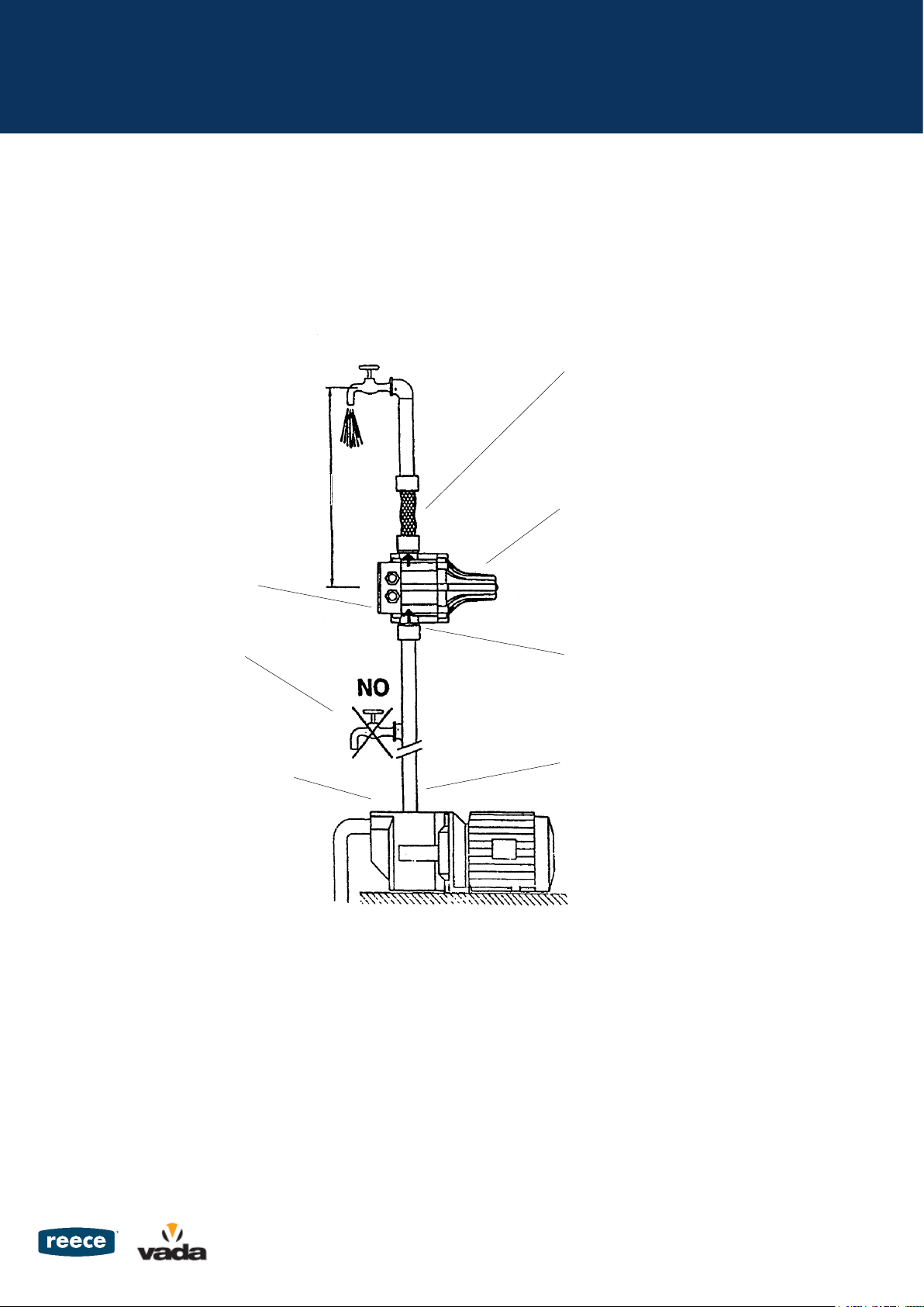
Cut-In 150 kPa
Max. Water temperature 65°C
Inlet/Outlet 1” BSP Male
Disclaimer:
The manufacturer/distributor reserves the right to vary specifications or delete models from their range without prior notification. Dimensions and
set-outs listed are correct at time of publication however the manufacturer distributor takes no responsibility for printing errors.
SPECIFICATIONS
Dear Customer,
This is the warranty by Reece Pty. Ltd. relating to your product.
Please keep it together with your purchase receipt. In the event of a
query please contact your nearest Reece Plumbing Centre.
Warranty
You have purchased a quality product from Reece Australia. This
product is covered by a 12 month warranty. This warranty covers
faults in the product construction, material and assembly. Faulty
products will be repaired or exchanged free of charge. Faulty items
become our property.
Please note that every product is subject to a stringent final inspection
before it is delivered.
This warranty does not include faults caused by
• Unsuitableorimproperuse
• Incorrectinstallation
• Normalwearandtear
• Inadequateorcompletelackofmaintenance
• Chemical,electrochemicalorelectricalinfluences.
Warranty repairs may only be performed by our service representa-
tives or an authorised customer service workshop.
Any attempt to repair the device by the customer or unauthorised
third parties shall terminate the warranty.
Any warranty service granted by Reece will neither extend the period
of the warranty nor will any new warranty period be justified for any
parts repaired or replaced by us.
To the maximum extent permitted by law, Reece excludes all warran-
ties other than those set out above. In the event of a warranty claim,
we will replace or repair defective products, or pay for the cost of
having defective products repaired or replaced, but will not be liable
for any injury to any person, damage to any property, any indirect or
consequential loss, or in any other respect.
WARRANTY & CARE DETAILS
It is hereby declared that the item below conforms with the following directives:
•AS/NZSCISPR14AS/NZS60335.1AS/NZS60335.2.41
0 50 100 150
Flow (litres/minute)
18
16
14
12
10
8
6
4
2
0
Head (metres)
Auto Pressure Control Pressure Loss
VADA - V-PC Auto Pressure Control
If the column of water between the pump and
the highest tap exceeds 15m, the unit cannot
be installed directly on the pump, it has to
be raised until the column of water between
the unit and highest tap does not exceed
15m. i.e. If column of water is 20m from the
pump, the unit must be place 5m higher than
the pump.
The pressure control is equipped with a
check valve to prevent the pipeline from
losing pressure.
Notapscanbeinstalledbetweenthe
pressure system and the pump.
PUMPPRESSURE
The pressure control is pre-set by the
manufacturer at a restarting pressure of 1.5
bar. The pressure produced by the pump
must be normally 0.8 bar higher than the set
pressure.
Before starting the unit, check suction and
ensure the pump is primed.
It is advisable to connect the pressure control to the
system by means of a flexible hose.
Safety valve preventing water emission in case of
diaphragmdamage.DONOTTOUCH.
It is imperative to install the pressure control with the
arrows in an upward position.
The pressure control can be installed directly on the
pump, or between the pump and first tap.
Installing the Auto Pressure Control Correctly
15m max.
1. Pressure Control Installation
The Vada Auto Pressure Control comes fully wired and is ready for use with the pump. Please ensure the pumps current rating is below 10 amps or
that the automatic pump control is configured so as the current to the unit is less than the maximum current rating of 10 amps.
Warning:Nevertaketheelectronicboardoutofthecontrolbox.Thewiringdiagraminsidethefrontpanelwillshowyouhowtomakecorrect
connection. Wrong connection will destroy the whole electronic circuit. If extending the cable used for connection it must be three wired with a
grounded end. It shall have the outer diameter at 7.5mm min and 8.5mm max. The two cables must be goose necked so that part of the cable is
lower than the position of the fixing nuts to reduce the chance of water running into the conroller, as shown in the figure below.
The four screws on the panel board and the two nuts for fixing cable must be well fastened to avoid water entering into the control box and
damaging the electronic circuit.
2. Starting & Operation
Whentheunitisconnectedtothepowersupplyandpowerisavailable,thegreenLEDindicating“poweron”illuminates.TheyellowLEDilluminates
to show the pump is in operation. On initial start up the pump will run until the supply line is primed.
When a tap is opened the pump will start automatically and continue to run at constant pressure. When the tap is closed, the pump will run on for
a short period until the system is again pressurised and then stop.
Shouldthepumpfailtoprime,theredLEDindicating“failure”willilluminateandthepumpwillstop.Thisensurethepumpisprotectedagainstloss
of prime. It will be necessary to press the restart button to have the pump restart.
Should the system fail again, it is recommended the pump is isolated from the power, system pressure relieved and the problem investigated by a
suitably qualified person.
Once starting operation is achieved, the unit is programmed to perfrom all the pump control operations automatically. When particular operational
breakdownsoccursuchaswaterfailure,obstructionofthesuctionpipeetc.theunitrecognisesthebreakdownandthered“failure”LEDlightsup,
at the same time as a stop signal is sent to the pump to prevent damage caused by its working in the absence of water. Rectification of the failures
thathavecausedtheblockageallowsthesystemtoberestartedbypressingthe“restart”button.
When using a generator to power the Auto Pressure Control, ensure the output of the generator is a full sine wave to mimick 240V.
VADA - V-PC Auto Pressure Control
The four screws
must be fastened
The two nuts for fixing
cables must be fastened
This part must be lower
than the fixing nuts
Three-wire cable with the
OD 7.5mm - 8.5mm
Power
Pump
Inlet
VADA - V-PC Auto Pressure Control
Trouble Cause related to Pressure Control Causes not related to pressure control
 Pumpwon’tstart  •Theelectroniccardisbroken •Voltagefailure
       •Pumpjammed
       •Electriccablesinverted(line/motor)
Pumpwon’tstop  •Theelectroniccardisbroken •Presenceofleakswhicharehigherthantheminimumflowof0.6
   •Theresetbuttonisblocked  l/min
   •Theflowdetectorisblockedintheupper      
position
   •Thepumpdoesnotprovidesufficient       
pressure
Intermittentpumpworking  •Theelctroniccardisbroken  •Presenceofleakswhicharehigherthantheminimumflowof0.6
   •Thepumpdoesnotprovidesufficient l/min      
pressure
Pumpisjammed  •Theelectroniccardisbroken •Waterfailure     
   •Thepumpprovidesapressurewhich       
is lower than the restarting pressure
TROUBLESHOOTING - Auto Pressure Control

Popular Control Unit manuals by other brands

Interlogix Simon XT installation instructions

Interlogix

Interlogix Simon XT installation instructions

Comelit K1406 Technical manual

Comelit

Comelit K1406 Technical manual

Camille Bauer EMMOD 204 operating instructions

Camille Bauer

Camille Bauer EMMOD 204 operating instructions

SMC Corporation EX260-SPN1 Operation manual

SMC Corporation

SMC Corporation EX260-SPN1 Operation manual

Nice FGR-223 instruction manual

Nice

Nice FGR-223 instruction manual

VAT 642 Series Installation, operating,  & maintenance instructions

VAT

VAT 642 Series Installation, operating, & maintenance instructions

GEM R647 Installation, operating and maintenance instructions

GEM

GEM R647 Installation, operating and maintenance instructions

Aaeon NanoCOM-U15 manual

Aaeon

Aaeon NanoCOM-U15 manual

DVC C2 instruction manual

DVC

DVC C2 instruction manual

Festo CPX-E- DI Series Instructions & Operating

Festo

Festo CPX-E- DI Series Instructions & Operating

MAYSER SG-EFS 104/2W operating instructions

MAYSER

MAYSER SG-EFS 104/2W operating instructions

Oxygen HYDRA 230V Technical manual

Oxygen

Oxygen HYDRA 230V Technical manual

Truma BCU 120 Operating instructions & installation instructions

Truma

Truma BCU 120 Operating instructions & installation instructions

GEM F60 operating instructions

GEM

GEM F60 operating instructions

LumenRadio W-Modbus manual

LumenRadio

LumenRadio W-Modbus manual

AzureWave AW-CU427-P Getting started guide

AzureWave

AzureWave AW-CU427-P Getting started guide

Dyna-Flo 360 Operation, Parts, and Instruction Manual

Dyna-Flo

Dyna-Flo 360 Operation, Parts, and Instruction Manual

NI 9350 Getting started guide

NI

NI 9350 Getting started guide

manuals.online logo
manuals.online logoBrands
  • About & Mission
  • Contact us
  • Privacy Policy
  • Terms and Conditions

Copyright 2025 Manuals.Online. All Rights Reserved.