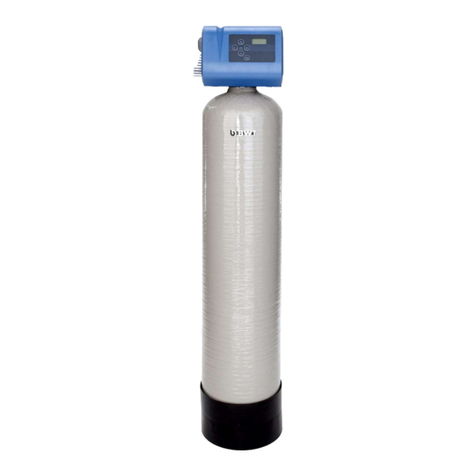
Reece BWT Multipur AP Series User manual

1-510475 / 12572 / 2019-02 / © BWT Wassertechnik GmbH / Printed in Germany
Changes reserved!
Installation and operating manual AUS
Multipur AP
DN 65 – DN 150
Backwash lter
Device must be installed immediately
downstream of an AS/NZS 2845.1
backow prevention valve!
Please contact your plumber!
Suitability:
Suitable for domestic and commercial
installations to remove sediment and
improve the service life of plumbing
xtures and ttings. Product Approval:
The product is certied to ATS 5200.103

2
Thank you very much for the
confidence that you have
shown in us by purchasing a
BWT appliance.
AUS
Table of Contents Page 3

3
3
AUS
Table of Contents
1 Safety Instructions 4
1.1 General safety instructions 4
1.2 Scope of the documentation 4
1.3 Personnel qualications 4
1.4 Transport and installation 5
2 Use 5
2.1 Intended use 5
2.2 Foreseeable misuse 5
2.3 Disclaimer 5
2.4 Other applicable documentation 5
3 Scope of supply 6
4 Function 6
5 Preliminary installation conditions 7
6 Installation 8
7 Commissioning 9
7.1 For parallel operation only 10
8 Operation 10
8.1 Setting the backwash interval 10
8.2 Manual backwashing 10
8.3 Display 10
8.4 Cleaning 10
9 Maintenance 11
9.1 Replacement of wearing parts 11
9.2 Troubleshooting 11
10 Warranty 11
11 Decommissioning and disposal 11
11.1 Decommissioning 11
11.2 Disposal 11
12 Technical Data 12
12.1 Overall dimensions 14
12.2 Volume ow rate and pressure loss 15
12.3 Pressure loss curves 16
12.4 Type label 17

4
AUS
1 Safety Instructions
1.1 General safety instructions
The product was manufactured according to all
recognised regulations and technical standards and
was in compliance with the relevant legal require-
ments when it was put into circulation.
Nevertheless, it can pose a risk of personal injury
or property damage if you do not observe this
chapter and the safety instructions throughout this
documentation.
● Read this documentation thoroughly and in full
before working with the product.
● Retain the documentation in such a way that it is
accessible to all users at all times.
● Always hand over the product to third parties to-
gether with the full documentation.
● Follow all of the instructions in relation to the
proper handling of the product.
● If you detect damage to the product or the mains
supply, stop its operation and notify a service
technician immediately.
● Use only accessories, spare parts and consu-
mable materials that have been approved by
BWT.
● Adhere to the environmental and operating con-
ditions specied in the “Technical data” chapter.
● Use your personal protective equipment. It en-
sures your safety and protects you from injury.
● Only perform tasks that are described in these
operating instructions or if you have been trai-
ned to do so by BWT.
● Perform all tasks in compliance with all appli-
cable standards and provisions.
● Instruct the operator in the function and operati-
on of the product.
● Instruct the operator in the maintenance of the
product.
● Instruct the operator in relation to potential dan-
gers that may arise while operating the product.
1.2 Scope of the documentation
This documentation applies exclusively to the
product the production number of which is listed
in chapter 12 “Technical Data”.
This documentation is intended for operators,
installers without training from BWT, installers with
training from BWT (e.g. drinking water specialists),
and BWT service technicians.
This documentation contains important information
for tting the product safely and properly, starting
up, operating, using, maintaining, and disassem-
bling the product, and for correcting simple faults
independently.
Read this documentation in full before working with
the product. Pay particular attention to the chapter
“Safety Instructions”.
1.3 Personnel qualications
The installation work described in these instructions
requires basic knowledge of mechanics, hydraulics
and electrical systems as well as knowledge of the
corresponding specialist terms.
To ensure that the device is installed safely, this work
must be performed only by a qualied specialist or
a trained person under the guidance of a qualied
specialist.
A qualied specialist is anyone who can assess
the work assigned to him or her, identify potential
risks, and take suitable safety measures thanks
to his or her specialist training, knowledge and
experience as well as his or her knowledge of the
applicable regulations. A qualied specialist must
comply with the applicable specialist regulations.
An instructed person is anyone who has been
instructed and, if necessary, trained by a qualied
specialist in the transferred tasks and the potential
risks presented by improper behaviour and who
has been educated about the necessary protective
equipment and measures.

5
5
AUS
1.4 Transport and installation
To avoid damage during transport to the installation
location, do not remove the BWT product from the
packaging until you have reached the relevant lo-
cation. Then dispose of the packaging in the correct
manner. Check that the delivery is complete.
If there is a risk of frost, drain all components that
convey water.
Lift or transport the product or its components only
from the designated suspension eyes or attachment
points, if present.
The product must be installed or mounted on a suf-
ciently strong and level horizontal surface and must
be adequately secured against falling or tipping.
2 Use
2.1 Intended use
The Multipur backwash lters are used for ltration
of drinking and industrial water to protect the wa-
ter mains and the connected ttings, equipment,
machinery, tanks, boilers and production facilities
from malfunction and corrosion damage caused by
foreign particles.
The lters can also be used for ltration of well,
process, boiler feed, cooling and air conditioning
water. In these cases, advice must be obtained
from a specialist.
The lters are unsuitable for oils, greases, solvents,
soaps and other lubricating media. Water-soluble
substances also cannot be separated off.
2.2 Foreseeable misuse
Operating the system with parameters other than
those specied in this documentation and in sec-
tion 2.1.
Not adhering to the prescribed maintenance and
service intervals.
Using spare parts and consumables not approved
by BWT.
2.3 Disclaimer
The manufacturer is released from any liability if the
customer intentionally or forcibly removes guards
or safety devices, if the customer wilfully modies
or circumvents the same, or if the customer does
not follow the instructions in this operating manual
or on the system.
2.4 Other applicable documentation
Observe all documents from suppliers that were
included with delivery. These are considered part
of this documentation and must not be changed
or removed.

6
AUS
3 Scope of supply
Backwash lter Multipur AP, consisting of:
1Filter housing made of red brass
2Electronic controller and backwashing de-
vice with hydraulic drive, CIC connection
3 Power supply unit
4Water outlet for pipe / water outlet for hose
(20 mm Ø)
5Pressure gauge
CIC connection cable
Accessories
Interlock cable for parallel
operation 2 m, with plug
Order no.
10908
4 Function
The untreated water flows through a stainless
steel lter element in the Multipur. Foreign particles
> 100 µm are thus retained. Depending on their size
and weight, these particles either fall directly into
the lower part of the lter housing, or adhere to the
lter element.
During backwashing, the seal at the rinsing water
outlet opens. The suction ring segments of the
backwashing element move from the bottom to the
top and back again over the entire lter surface and
thus clean the lter fabric by suction with clean water
at an extremely high ow rate.
Backwashing is carried out automatically at the end
of the set interval.
The pressure difference between the untreated
water inlet and the treated water outlet of the lter
is measured.
The backwashing process is triggered primarily by
differential pressure.
If heavy soiling of the lter element causes the
pressure difference to exceed the preset value
(approx. 80 kPa) within the preset backwash inter-
val, the differential pressure generator causes the
unit to backwash. The preset backwash interval
starts again.
The lter is equipped with a central instrumentation
and control (CIC) connection (contact closes in the
event of malfunction or power failure).
2
1
4
5
3

7
7
AUS
5 Preliminary installation con-
ditions
Local plumbing codes, general guidelines and the
technical data must be observed.
The system must be installed by the water supply
utility or a plumbing company approved by the water
supply utility in accordance with these installation
and operating instructions and the applicable re-
gulations.
The installation site must be frostproof and ensure
that the lter is protected from solvent vapours,
heating oil, lees, acidic cleaners, chemicals of all
kinds, direct UV radiation and heat over 40 °C.
A separate power socket (230 V AC, 50 Hz) within
a distance of approx. 1.2 m is required. The power
supply must be permanently ensured. Voltage peaks
over 1 kV must be avoided.
If the water contains dirt particles > 2 mm, a coarse
dirt trap must be installed upstream from the lter.
A ushing water quantity of at least 1.4 l/s (5 m³/h)
must be available for backwashing.
A drainage connection (min. DN 50/75) must be
available for discharge of the rinsing water.
Avoid extreme pressure surges (caused, for ex-
ample, by downstream solenoid valves or similar).
> 400 mm
0 0 0
m3
For Multipur AP 65, Multipur AP 80
and Multipur AP 100:
Drainage connection min. DN 50
For Multipur AP 125 and Multipur AP 150:
Drainage connection min. DN 75

8
AUS
6 Installation
Install the backwash lter horizontally in the cold
water line in the ow direction. (Observe the ow
direction arrow on the lter casing.)
Piping must be conducted according to AS/NZS
3500.1
Screw on the waste water connection, either for pipe
or for hose. Connect the drain line.
According to AS/NZS 3500.2 pipes discharging over
a tundish shall have an airgap of a size at least
twice the internal diameter of the discharging pipe.
If desired, an external fault signal issued by a
potential-free contact can be connected to the
building automation system terminals.
Put in pressure relief hose from the solenoid valve in
the upper cutout of the drain connection respectively
in the sloping drill hole of the hose liner.
A mains power outlet must be available in the
immediate vicinity (max. 1.2 m away). The power
supply unit is rated at IP40.
For Multipur AP 65, Multipur AP 80
and Multipur AP 100:
Drainage connection min. DN 50
For Multipur AP 125 and Multipur AP 150:
Drainage connection min. DN 75
Insert pressure relief hose
> 40 mm
> 1 m
> 400 mm
0 0 0
m3
Connection to
RR PP 50 mm waste
Connection to
20 mm I.D. hose
24 V
3

9
9
AUS
7 Commissioning
Check that the lter and ushing water pipe have
been properly installed.
Slowly open the stop valves up- and downstream of
the lter. Deaerate the pipework at the next bleed
point downstream of the lter, and drain water briey.
Check the seals of the installation and lter for leaks.
Insert the cable plug connector of the power supply
unit into the socket (24 V).
Plug in power supply unit with plug (3). The rst
backwashing cycle is performed automatically
(during backwashing the illuminated segments on
the display turn).
The factory setting (7 days) appears.
The required backwash interval must be set on
the lter.
Press Set to set the interval.
Key Display
Press Set for 5 seconds SL 0
Display dots ash - device is in programming
mode
Press Set SL 1
Press Set SL 2
Press Set SL 3
Press Set 1 h
Pressing the Set key again steps up the number of
h (hours) or d (days).
The hours h run from 1 – 24, followed by days d from
2 – 56, followed by the hours again etc.
Press the Set key until the desired value has been
set. The value is saved 10 seconds after the last in-
put. The display dots fade out. The unit backwashes.
The time until the next backwashing and the pres-
sure difference appear alternately in the display.
The pressure difference is only displayed for large
volumes of water.
The lter is ready for use.
CIC24 VSignal IN Signal OUT
Set

10
AUS
7.1 For parallel operation only
When 2, 3 or a maximum of 4 lters are operated
in parallel, they must be electrically interlocked to
prevent simultaneous backwashing.
Insert an interlocking cable into the output of any
one lter, representing lter 1, and run the cable to
the input of lter 2. Insert the next interlocking cable
into the output of lter 2, and run it to the input of
lter 3. The output of the last lter is returned to the
input of lter 1.
The required backwash interval must be set at the
lter to be backwashed rst (master) (see above).
The second lter (slave) must be set as follows:
Key Display
Press Set for 5 seconds SL 0
Display dots ash - device is in programming
mode
Press Set SL 1
Wait 10 seconds, dots stop ashing.
The pressure appears in the display (0.0 P, when
no water is used).
A third lter must be set to SL 2 and a fourth to SL 3.
Disconnect and reconnect all lters to the mains
power supply. The lters will be backwashed in
sequence: Master, SL 1, SL 2 and SL 3.
The time until the next backwashing and the pres-
sure difference appear alternately in the master lter
display. The pressure difference is only displayed
for large volumes of water.
Only the pressure difference appears in the slave
lter display.
The lters are ready for use.
8 Operation
We recommend programming the lter so that the
device is backwashed at least once a month to
prevent foreign particles from adhering to the lter
element (more frequently for higher levels of soiling;
factory setting every 7 days).
8.1 Setting the backwash interval
Should the local water quality (degree of contami-
nation) change, the backwashing interval must be
corrected; see commissioning.
8.2 Manual backwashing
Unplugging and plugging in the device can back-
wash it at any time.
8.3 Display
The time until the next backwashing and the pres-
sure difference appear alternately in the display.
The pressure difference is only displayed for large
volumes of water.
8.4 Cleaning
Clean plastic parts with a soft, damp cloth only;
do not use solvents, detergents, or acidic cleaning
agents.

11
11
AUS
9 Maintenance
It is recommended and to assist in the longevity of
your Multipur unit, that regular maintenance occurs.
This should always be undertaken by specialist staff
who will also replace worn parts.
We advise you to conclude a maintenance contract.
Maintenance must be performed once each year,
and twice each year for municipal systems, by your
local plumber/installer.
9.1 Replacement of wearing parts
Seals every 3 years
Backwashing element every 6 years
Filter element every 6 years
Groove ring every 6 years
Lock ring every 6 years
Hose barb every 9 years
HT-Connector every 9 years
Hydraulic tubes every 9 years
Difference pressure
transducer
every 9 years
Pressure spring every 12 years
9.2 Troubleshooting
Fault Cause Action
Water pressure dropped
considerably in network
Dirty lter element Carry out backwash
Flushing water outlet
does not close
Backwash element does not
reach the end position due to
large particles of dirt
Repeat backwash several times
AP only:
Display shows ERR
Pressure too low Repeat backwash several times.
Increase pressure
If the fault cannot be remedied by following these tips, contact our after-sales service department.
10 Warranty
In the event of a malfunction during the warranty
period, please contact our after-sales service de-
partment, stating the type of unit and the product
number (PNR) (see the technical data or the type
plate on the unit).
11 Decommissioning and dis-
posal
11.1 Decommissioning
The product may only be shut down and dismantled
by qualied specialists.
Observe all applicable safety regulations when
dismantling the system.
11.2 Disposal
NOTICE
►At the end of the product's life cycle,
ensure that it is properly disposed of or
recycled.
►Observe the legal disposal guidelines for
the country in which the product is used.
►The following materials are used in the
product: metal, plastic

12
AUS
12 Technical Data
Multipur AP Type 65 80 100
Nominal connection width DN 65 80 100
Connection type Flange connection DIN 2501, Part 1
Flange Ø mm 145 160 180
Flangebore Ø mm 18
Nominal ow m3/h 58 82
Flow capacity at ∆p = 20 kPa m3/h 35 56
Flow capacity at ∆p = 50 kPa m3/h 58 82
Micron rating µm 100
Nominal pressure (PN) kPa 1000
Operating pressure po min./max. kPa 250 – 1000
Recommended operating pressure kPa 250 – 800
Minimum pressure behind lter
(for backwashing)
kPa
250
Water temperature , min./max. °C 5 / 30
Ambient temperature, min./max. °C 5 / 40
Length of backwashing, approx. s10
Rinsing water volume at 400 kPa l16 24
Water ow at backwashing l/h 5700 8600
Mains connection V/Hz 230/50
Operating voltage V- 24
Power consumption, max. W 8
Power consumption during
backwashing, max.
W
12
CIC - dry contact,
switching capacity max.
V / A
24 / 1 (resistive load)
Protection class IP54
Drainage connection, min. DN 50
Operating weight, approx. kg 15 18 24
Shipping weight, approx. kg 13 16 21

13
13
AUS
Technical Data
Multipur AP Type 125 150
Nominal connection width DN 125 150
Connection type Flange connection DIN 2501, Part 1
Flange Ø mm 210 240
Flangebore Ø mm 18 22
Nominal ow m3/h 91 105
Flow capacity at ∆p = 20 kPa m3/h 57 61
Flow capacity at ∆p = 50 kPa m3/h 91 105
Micron rating µm 100
Nominal pressure (PN) kPa 1000
Operating pressure po min./max. kPa 250 – 1000
Recommended operating pressure kPa 250 – 800
Minimum pressure behind lter
(for backwashing)
kPa
250
Water temperature , min./max. °C 5 / 30
Ambient temperature, min./max. °C 5 / 40
Length of backwashing, approx. s10
Rinsing water volume at 400 kPa l30
Water ow at backwashing l/h 10000
Mains connection V/Hz 230/50
Operating voltage V- 24
Power consumption, max. W 8
Power consumption during
backwashing, max.
W
12
CIC - dry contact,
switching capacity max.
V / A
24 / 1 (resistive load)
Protection class IP54
Drainage connection, min. DN 75
Operating weight, approx. kg 33 38
Shipping weight, approx. kg 28 32

14
AUS
12.1 Overall dimensions
Multipur AP Type 65 80 100
Overall height mm 630 630 680
Height, top edge to centre of tube (H1) mm 310 310 310
Height, lower edge to centre of tube (H2) mm 320 320 370
Minimum distance, centre of tube to ceiling (H3) mm 400 400 400
Minimum distance, centre of tube to oor (H4) mm 400 400 400
Minimum distance, centre of tube to wall mm 100 105 115
Installation length (L) mm 220
Multipur AP Type 125 150
Overall height mm 770 770
Height, top edge to centre of tube (H1) mm 310 310
Height, lower edge to centre of tube (H2) mm 460 460
Minimum distance, centre of tube to ceiling (H3) mm 400 400
Minimum distance, centre of tube to oor (H4) mm 640 640
Minimum distance, centre of tube to wall mm 130 145
Installation length (L) mm 220
DN 65
DN 80
DN 100
DN 125
DN 150
H2H1
L
H3
H4

15
15
AUS
12.2 Volume ow rate and pressure loss
Multipur AP DN 65
Volume ow rate [m³/h] 15 22 35 44 51 58 72 81
Pressure loss ∆p [kPa] 510 20 30 40 50 80 100
Multipur AP DN 80
Volume ow rate [m³/h] 15 22 35 44 51 58 75 85
Pressure loss ∆p [kPa] 510 20 30 40 50 80 100
Multipur AP DN 100
Volume ow rate [m³/h] 29 41 56 67 75 82 102 114
Pressure loss ∆p [kPa] 510 20 30 40 50 80 100
Multipur AP DN 125
Volume ow rate [m³/h] 26 38 57 70 81 91 116 132
Pressure loss ∆p [kPa] 510 20 30 40 50 80 100
Multipur AP DN 150
Volume ow rate [m³/h] 25 40 61 79 93 105 137 155
Pressure loss ∆p [kPa] 0 10 20 30 40 50 80 100

16
AUS
12.3 Pressure loss curves
0
10
20
30
40
50
60
70
80
90
100
110
0 10 20 30 40 50 60 70 80 90 100 110 120
Mulpur DN 65, DN 80 und DN 100
1 2 3
kPa
m
3
/h
0
10
20
30
40
50
60
70
80
90
100
0 20 40 60 80 100 120 140 160
kPa
m3/h
4 5
Multipur DN125, DN 150
1 = Multipur DN 65
2 = Multipur DN 80
3 = Multipur DN 100
4 = Multipur DN 125
5 = Multipur DN 150

17
17
AUS
12.4 Type label
The type label serves as product identier. In case
of any requests, please have the following infor-
mation ready:
1. Device name
2. Production number / Order-no.
3. Serial number / Year of manufacture
Note: The type label is an ofcial document and
must not be altered or stripped off. Dama-
ged or unreadable type labels have to be
replaced.
3
2
1

18

19
19

Further information:
Reece. Works
for you. ™
Call 1800 032 566 or visit
www.reece.com.au for your
nearest Reece store.
Due to limitations in the printing process
the colours in this brochure are a guide
only.
The manufacturer/distributor reserves
the right to vary specications or delete
models from their range without prior
notication. The manufacturer/distributor
takes no responsibility for printing errors.
www.reece.com.au
This manual suits for next models
5
Table of contents
Other Reece Water Filtration System manuals
Popular Water Filtration System manuals by other brands

GCTek
GCTek AquaBead System instructions

Potterton
Potterton ZLF 160 installation manual

amiad
amiad SAF X Series Installation, operation & maintenance instructions

Beko
Beko QWIK-PURE 200 Instructions for installation and operation

SKF
SKF Lincoln 84013 Installation instruction

Excalibur Water Systems
Excalibur Water Systems FILTERMAX ZENTEC Installation and user guide