Reed Manufacturing RG26 Series User manual

1
RG26 Series Roll Groover Operator’s Manual
809-50356
REED MANUFACTURING COMPANY
1425 West 8th St. P.O. Box 1321, Erie, Pa 16512 USA Phone: 800-666-3691 or 814-452-3691 Fax: 800-456-1697 or 814-455-1697
www.reedmfgco.com
Pipe Tools & Vises
Since 1896
OPERATOR’S MANUAL
RG26 Series
ROLL GROOVER
Operation, Maintenance and Service Instructions
Includes: RG26S and RG26CU

2
RG26 Series Roll Groover Operator’s Manual
809-50356

3
RG26 Series Roll Groover Operator’s Manual
809-50356
IMPORTANT:
Read and fully understand this operating manual before
operating or performing maintenance on the RG26 Roll
Groover. It is essential to properly train and review with
operating personnel to become familiar with the tool’s op-
erations, applications, and limitations to prevent possible
bodily injury and property damage. All personnel should be
aware of the tool’s specific hazards.
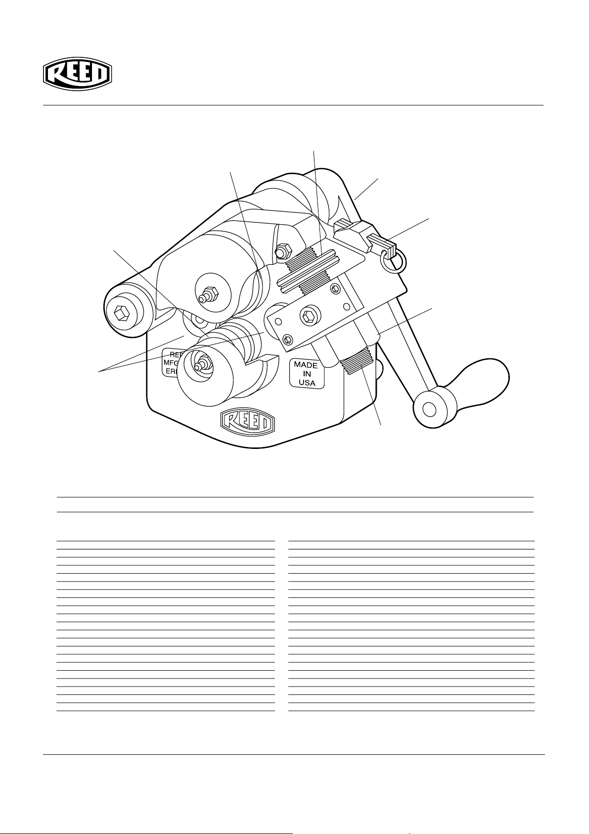
Reed RG26 Series Roll Groover
Description and Specifications
Description
The Reed RG26S Roll Groover is designed to form stan-
dard rolled grooves in steel, stainless steel, PVC, and alu-
minum pipe in 2-6" schedule 10, and 2-3" schedule 40.
The Reed RG26CU Roll Groover is designed to form stan-
dard rolled grooves in 2” to 6” copper tubing. The groove is
formed by a groove roll which is fed into the pipe wall. The
pipe is supported by a drive roll, which is relieved to permit
pipe wall deformation. The formed grooves comply with the
specifications required for mechanical coupling systems.
The only adjustment required is for the depth of the groove.
Designed for ease of use and portability, the RG26 Series
Roll Groover provides a practical solution for manual on-
site and in-place roll grooving.
Specifications
Capacity RG26S.................................2” - 6” Schedule 10
2” - 3” Schedule 40
Capacity RG26CU............2” - 6” K,L,M, and DWV Copper
Depth Adjustment ...........................Adjusting Nut, Depth
Gauges (included), and Jam Nuts
Actuation .................................Crank Nut and Ratcheting
Crank Handle (included)
Weight ........................................................21 lbs (9.55 kg)
Recommended Accessories
• Reed R450+ TriStand, Field Pipe Vise, CV6 bench
mounted chain vise, or #64 yoke style vise (when not us-
ing in-place)
• Reed JHV Pipe Jack (for long pipe lengths)
Important - Before Operating
Before operating the RG26 Roll Groover, read and
follow all safety information in the Operator’s Manual.
Safety Information
WARNING !
Serious injury can occur if all safety information and
operating instructions are not followed. These injuries
could include:
Loss of fingers, hands, arms or other
body parts if clothing or gloves get
caught in moving parts.
Impact injuries, including broken bones
if roll groover or workpiece falls.
Wear eye protection to prevent eye
injuries by thrown workpiece or
workpiece chips.
General Safety
Read and follow the safety information and instructions in
the operator’s manual.Store the operator’s manual in a clean
area and always at a readily available location. Additional
copies at no charge can be obtained by requests to Reed
Manufacturing Company.
Personal Safety
1. Wear snug-fitting clothes, safety shoes, hard hat and
safety glasses. Cover up or tie up long hair. Do not wear
loose clothing, gloves, unbuttoned jackets, loose sleeve
clothes, neckties, rings, watches or other jewelry.
2. Keep good footing and balance. Do not overreach. Keep
hands and tools away from moving parts of the roll
groover.
Work Area Safety
1. Keep children and visitors out of the work area. If visitors
must be in the area, keep them far away from the ma-
chine. Keep working environment clear at all times. When
using this tool at elevated locations or for overhead groov-
ing, keep area below clear of other personnel.
2. Keep work area clean, uncluttered and well lighted.
3. Keep floors dry and free of slippery materials.

4
RG26 Series Roll Groover Operator’s Manual
809-50356
Roll Groover Safety
1. When operating, keep hands away from grooving rolls.
Fingers could get caught between the groove roll and
drive shaft.
2. When setting up and using, make sure the Roll Groover
is secured to the pipe. Carefully follow set-up instruc-
tions.
3. Do not use the Roll Groover for any other purpose than
roll grooving pipe and tubing.
4. Do not use excessive force in turning the feed nut. Follow
operating instructions.
5. Be sure pipe or tubing is secure in a pipe vise or securely
hung in-place. Support long lengths of pipe or tubing with
a pipe jack.
6. Use recommended accessories. Use of other accesso-
ries may increase the risk of injury. Refer to the recom-
mended accessories section in the front of this manual.
Machine Maintenance
1. Inspect the equipment. Prior to using the tool, check the
movable parts for any obstructions. Be certain that all
tool parts are properly installed and secured
2. Inspect groove roll and drive shaft. Replace when neces-
sary.
3. Lubricate with multi-purpose grease through the three
grease fittings.
4. Keep the ratcheting crank handle dry and clean.
CAUTION
This tool is designed for manual operation only. This
tool is not to be driven by any power drive devices. The
use of power drive devices may present risk to the op-
erator and cause damage to the tool.
CAUTION
When using this tool at elevated locations, the area
below must be kept clear of other personnel.
RG26 tools are individually packaged in heavy cardboard
containers. Upon receipt, check to be certain the tool is the
correct model and all necessary parts are included.
Included should be:
(1) RG26 tool
(1) Set of depth gauges (attached to tool)
(1) Ratcheting crank with 1 1/4" socket
(1) Operator’s Manual
If incomplete, contact your Reed Distributor or Reed
Manufacturing Company.
Tube/Pipe Preparation
For satisfactory tool operation, the following tube/pipe prepa-
ration tips should be carefully observed:
1. Tube/pipe must be square cut.Do not use a cutting torch.
Note: When adjusting for roll groover depth, the trial
groove pipe should not have a large burr protruding in-
ward. Use a suitable tool for deburring the pipe or tub-
ing. After the groove depth has been set, deburring of
the pipe is not required.
2. The end of the tube/pipe, both inside and out, should be
cleaned of coarse scale, dirt or other materials which
might interfere with or damage the grooving rolls or dis-
tort the groove. Large weld beads are to be ground to
permit smooth rolling operation.
Pipe Set-Up
The RG26 is an orbital roll grooving tool which rotates
around a pipe held stationary. The pipe may be held in a
pipe vise during grooving. The RG26 also grooves piping
in a depressurized, in-place piping system.
Pipe Vise Set-Up
The choice of grooving location in the shop or field should
take into account the following factors:
• Pipe handling requirements
• Working space requirements for the tool and pipe
• Anchoring requirements for the pipe vise
Procedure
1. Securely mount pipe vise (chain type) on a secure stand or
workbench. Pipe vise should be mounted flush with or over-
hang the edge of the stand or workbench so, when the tool is
mounted on the pipe, the tool will rotate freely around the pipe
and not be obstructed by the bench or stand.
2. Secure pipe in pipe
vise, anchored to
hold securely the
weight of the tool
(21 lbs.) Position
the pipe to over-
hang the pipe vise
approximately 5 -
12" so the tool can
rotate in an unob-
structed manner.
(See Fig. 1.)
Fig. 1. Pipe Set-up

5
RG26 Series Roll Groover Operator’s Manual
809-50356
Groove-In-Place Set-Up
Previously installed piping may be grooved with the RG26,
providing the piping is securely supported.
NOTE: Pipe hangers must be able to accommodate the
weight of the 21 lb. (9.55 kg) RG26 plus the manual effort
to operate the tool (approximately 20 ft.-lb. torque) during
grooving.
WARNING
Piping systems must always be depressurized and
drained before attempting disassembly.
Failure to do so could result in serious injury, property
damage, joint leakage or joint separation.
Mounting Tool
1. Retract the upper roller fully by turning the brass feed nut
counterclockwise.
2. With the hex drive nut down, insert the nose of the body
into the pipe end. Push the tool onto the pipe until the
pipe end stops rest against the pipe end. (See Fig 2.)
3. Draw rolls together by turning the brass feed nut clock-
wise. Continue tightening until the grooving rolls are in
light, but firm contact with the pipe.
Adjusting Groove Depth
The Depth Stop Collars must be adjusted for each tube/
pipe size or change in wall thickness. Groove diameter,
identified as the “C” dimension for each tube/pipe size, is
listed under Standard Roll Groove Specifications - Steel
and Other IPS Pipe. For convenience, a “C” Diameter Chart
for the most common pipe sizes is also on the tool.
1. Unlock the depth stop collars by turning them in opposite
directions until they are separated.
2. Locate the groove depth gauge attached to the tool which
is identified with the pipe size to be grooved. Turn the
depth stop collar, closest to the trunnion, until the dis-
tance between the collar and the top of the trunnion is
equal to the groove depth gauge thickness. Use the
groove depth gauge like a feeler gauge. (See Figure 3.)
Fig. 3. Setting Gauge Depth
3.Turn the second collar until both are locked firmly against
one another, maintaining the gap set with the feeler
gauge. Replace the depth gauges back into the holder.
4. Prepare a trial groove by tightening the brass feed nut
the recommended turn increment, and then by turning
the crank nut clockwise until the roll groover has made
one full revolution around the pipe. (See Fig. 4.)
Fig. 2. Tool Insertion
Fig. 4.
Turning

6
RG26 Series Roll Groover Operator’s Manual
809-50356
Fig. 5. Turning crank handle
Note: Trial groove pipe should be deburred for best results.
A burr on the inside of the pipe will raise the pipe away from
the drive shaft, causing inaccurate set-up adjustment. After
proper groove depth has been verified by the trial groove,
deburring of the following pipes is not required. See Step 1
of “Tube/Pipe Preparation”
6. After a trial groove is prepared and the tool is removed
from the pipe, carefully check the groove diameter (“C”
dimension), a charted under Standard Roll Groove
Specifications - Steel and Other IPS Pipe, page 8, and
Drawn Copper Tubing Groove Specifications, page 9.
The “C” dimension is best checked with a pipe tape. It
may also be checked with a dial caliper or narrow land
micrometer at two locations, 90°apart, around the
groove. The average reading must equal the required
Groove Diameter.
CAUTION
The “C” Dimension (groove diameter) must always con-
form to specifications under Standard Roll Groove
Specifications, page 9, to ensure proper joint perfor-
mance.
Failure to do so could result in personal injury, prop-
erty damage, improper installation, joint leakage or joint
failure.
7. If groove diameter (“C” dimension) is not within tolerance,
adjust the depth stop collars to obtain the proper dimen-
sion. To adjust for a smaller groove diameter, turn the
depth stop collars counterclockwise. To adjust for a big-
ger groove diameter, turn collars clockwise. A quarter
turn either way will change the groove diameter by .017"
(.068" per full turn).
8. Prepare another trial groove and check the groove diam-
eter again. Repeat Steps 6 and 7 until groove diameter
is within specification.
Grooving Operation
NOTE: Reed RG26 tool is designed only for roll grooving
tube/pipe of the appropriate sizes. Grooving of tube/pipe
other than that recommended may not produce grooves of
proper tube/pipe end configuration or groove dimensions
necessary for joining.
Before Grooving:
• Review Safety Precautions before operating the tool.
• Check to be certain tube/pipe has been prepared
properly as detailed in
Tube/Pipe Preparation.
• Check to be certain pipe is properly supported as
detailed in
Pipe Set-Up.
• Check to be certain the tool is properly mounted on
the pipe. See
Mounting Tool.
• Check to be certain the depth stop collar is adjusted
correctly. See
Adjusting Groove Depth.
5.Continue turning the feed nut and cranking the tool around
the pipe. Once the jam nuts rest against the trunnion,
continue to crank the tool around for one more revolu-
tion. (See Fig. 5.)

7
RG26 Series Roll Groover Operator’s Manual
809-50356
CAUTION
Keep fingers, clothes, hair and objects other than tube/
pipe away from the rotating tool. Use safety glasses,
hardhat and appropriate footwear. Failure to do so
could result in personal injury.
1. Advance the feed by turning the feed nut clockwise by
the amount show in Table 1. Feed rates for the RG26
vary depending on material and pipe wall thickness.
Material Wall Thickness Turns of Feed Screw
inches/(mm) to Advance the Feed
.135 to .216 1/4 turn
(3.43 to 5.49)
.120 to .134 1/3 turn
Steel and (3.05 to 3.40)
Stainless Steel
.065 to .119 1/2 turn
(1.65 to 3.02)
.119 to .280 1/5 turn
(3.02 to 7.1)
.135 to .216 1/3 turn
(3.43 to 5.49)
Aluminum .120 to .134 1/2 turn
and (3.05 to 3.40)
Copper
.065 to .119 2/3 turn
(1.65 to 3.02)
PVC .154 to .258 3/4 turn
(3.91 to 6.55)
Table 1 - Feed Rates
Note: Over-tightening (overfeeding) will result in shortened
bearing life and other tool damage. Over or under-tighten-
ing could result in the tool “walking” off the pipe and eventu-
ally becoming disengaged from the pipe.
2. Place the ratcheting crank handle onto the drive hex.
Crank the drive hex nut clockwise until the tool travels
one full turn around the tube/pipe.
3. Advance the feed by turning the brass feed nut clock-
wise by the amount show in Table 1. Crank the tool an-
other full turn around the pipe.
4. Continue grooving by advancing the feed (Table 1) and
cranking the groover around the tube/pipe until the depth
stop collar comes in contact with the trunnion. At this
point, the brass feed nut can no longer be tightened.
Crank the tool at least one more full turn around the tube/
pipe after full groove depth is achieved.
5. After dismounting tool from pipe (see below), check
groove depth to ensure groove meets groove depth speci-
fication. NOTE: Groove Diameter should be correct for
the diameter and wall thickness of tube/pipe for which it
was set under Groove Diameter Stop Setting procedures.
Groove diameter should be checked periodically and ad-
justed as necessary.
Dismounting The Tool
1. Crank the tool until the drive hex is located in the down
position.
2. Turn the feed nut counterclockwise to retract the upper
roll arm to the full open position.
3. Lift the tool and remove it from the pipe. (See Fig. 6.)
Maintenance
1. Keep tool clean for best and safest performance.
2. Lubrication:
a) After approximately eight hours of operation, grease the
bearings at the three grease fittings on the tool. Use a
No. 2 EP Lithium base grease.
b) Weekly apply a light oil (SAE 10W-30 or equivalent) to
the threads where the feed screw passes through the
feed nut. Also, oil should be applied to the shoulder bolts
which hold the roll arm to the body, the feed screw to the
roll arm, and at the trunnion pivots.
Fig. 6. Dismounting the tool.

8
RG26 Series Roll Groover Operator’s Manual
809-50356
Problem Cause Solution
Unable to close Improper adjustment Turn depth stop collars counterclockwise,
rolls onto pipe. of depth stop collars. away from trunnion and reset depth stop collar,
as described in “Adjusting The Groove Depth.”
Groove too Improper adjustment Reset depth stop collars
deep (groove of depth stop collars. as described in “Adjusting Groove Depth.”
diameter too small).
Groove too Improper adjustment Reset depth stop collars
shallow (groove of depth stop collars. as described in “Adjusting Groove Depth.”
diameter too large).
Tool does not Rust or dirt has Remove accumulation from lower roll with stiff wire brush.
move when cranked. built up on lower roll.
Worn grooving rolls. Inspect lower roll for worn knurls, replace if worn.
Tool wobbles Variation in pipe Advance the feed at the rates described in Table 1.
during cranking. wall thickness or
inadequate feed rate.
Tool won’t track Tool is not correctly Reposition tool with pipe end stops against pipe.
(walks or falls off pipe). positioned on pipe.
Pipe end out of square. Trim pipe to square pipe end (see tube/pipe preparation).
Advance the feed at the rates described in Table 1.
Excessive fall off at
pipe end from use of
pipe cutter with
improper feed rate.
Tool crank turned in Turn feed and crank nuts clockwise.
wrong direction.
Tool won’t groove Tube/pipe beyond tool’s See rating charts.
tube/pipe. wall thickness capability.
Tube/pipe material Use recommended pipe material.
excessively hard.
Trouble Shooting

9
RG26 Series Roll Groover Operator’s Manual
809-50356
RG26S Roll Groove Diameter Specifications
A B C
NOM. PIPE GASKET GROOVE GROOVE
PIPE DIAMETER SEAT WIDTH DIAMETER
SIZE O.D. TOL. + .030 + .030 O.D. TOL. (+.000)
2 2.375 +.024/-.024 .625 .344 2.250 -.015
2-1/2 2.875 +.029/-.029 .625 .344 2.270 -.018
3 OD 3.00 +.030/-.030 .625 .344 2.845 -.018
3 3.50 +.035/-.031 .625 .344 3.344 -.018
3-1/2 4.00 +.040/-.031 .625 344 3.834 -.020
4 4.50 +.045/-.031 .625 .344 4.334 -.020
4-1/2 5.00 +.050/-.031 .625 .344 4.834 -.020
5 5.563 +.056/-.031 .625 .344 5.395 -.022
6 OD 6.00 +.056/-.031 .625 .344 5.830 -.022
6 6.625 +.063/-.031 .625 .344 6.455 -.022
RG26CU Roll Groove Diameter Specifications
A B C
NOM. PIPE GASKET GROOVE GROOVE DIAMETER
PIPE DIAMETER SEAT WIDTH O.D. TOL.
SIZE O.D. TOL. ±.030 ±.030 (+.000/-.020)”
2±.002 0.610 0.300 2.029
2 1/2 ±.002 0.610 0.300 2.525
3±.002 0.610 0.300 3.025
4±.002 0.610 0.300 4.019
5±.002 0.610 0.300 4.999
6±.002 0.610 0.300 5.999

10
RG26 Series Roll Groover Operator’s Manual
809-50356
18
12
36
15
8
13
10
19
Parts List
RG26S RG26CU
Ref. 08510 08512
No. Description Item Code Item Code
22 Bronze Bushing 40461 40461
23 Bronze Bushing 40473 40473
24 Washer Large 40462 40462
25 Washer Small 40463 40463
26 Groove Pin 30235 30235
27 Grease Fitting 40338 40338
28 Roller Bearing 40459 40459
29 Roller Bearing 40460 40460
30 Needle Roller Bearing 40458 40458
31 Roll Pin 30232 30232
32 Roll Pin 30233 30233
33 Flat Head Socket Screw 30216 30216
34 Dowel Pin 30218 30218
35 Retaining Ring 30219 30219
36 Socket Set Screw 30224 30224
37 Shoulder Screw 30228 30228
38 Shoulder Screw 30229 30229
39 Shoulder Screw 30227 30227
40 Lock Nut 30231 30231
41 Hex Machine Screw 30225 30225
42 Socket Head Cap Screw 30230 30230
RG26S RG26CU
Ref. 08510 08512
No. Description Item Code Item Code
1 Main Body 98520 98565
2 Yoke 98521 98521
3 Crank Assembly 98522 98522
4 Drive Shaft 98523 98523
5 Drive Shaft Gear 98524 98524
6 Crank Shaft Gear 98525 98525
7 Crank Shaft 98526 98526
8 Feed Screw 98527 98527
9 Groove Roll Shaft 98528 98528
10 Groove Roll 98529 98550
11 Cover Plate Assembly 98542 98542
12 Jam Nut 98531 98531
13 Drive Roll 98532 98551
14 Crank Nut 98534 98534
15 Feed Nut 98535 98535
16 Trunnion 98536 98536
17 Trunnion Plate 98537 98537
18 Depth Gauge Set 98549 98566
19 Thrust Button 98538 98538
20 Knurled Pin 98539 98539
21 Handle 98540 98540

11
RG26 Series Roll Groover Operator’s Manual
809-50356
Replacement Parts
3
7
14 32
21
20
6
18
4
15
35
16
8
1
17
42
2
38
27
27
12
9
13
25
26
10
36
33
29
34
28
19
5
11
24
24
37
40
30
22
31 23
33
41
39
34
27

12
RG26 Series Roll Groover Operator’s Manual
809-50356
REED MANUFACTURING COMPANY
1425 West 8th St. P.O. Box 1321, Erie, Pa 16512 USA Phone: 800-666-3691 or 814-452-3691 Fax: 800-456-1697 or 814-455-1697
www.reedmfgco.com
Pipe Tools & Vises
Since 1896
Reed Lifetime Warranty
Reed Hand Tools are for the professional trade and are warranted
against all failure due to defects in workmanship and materials for
the normal life of the tool.
FAILURES DUE TO MISUSE, ABUSE, OR NORMAL WEAR
AND TEAR ARE NOT COVERED BY THIS WARRANTY.
Power units for Universal Pipe Cutters and Threading Power
Drives are warranted for a period of one year from date of
purchase.
NO PARTY IS AUTHORIZED TO EXTEND ANY OTHER WAR-
RANTY. NO WARRANTY FOR MERCHANTABILITY OR FITNESS
FOR A PARTICULAR PURPOSE SHALL APPLY.
No warranty claims will be allowed unless the product in question
is received freight prepaid at the Reed factory. All warranty claims
are limited to repair or replacement, at the option of the company,
at no charge to the customer. REED IS NOT LIABLE FOR ANY
DAMAGE OF ANY SORT, INCLUDING INCIDENTAL AND CON-
SEQUENTIAL DAMAGES. Some states do not allow the exclu-
sion or limitation of incidental or consequential damages, so the
above exclusion may not apply.
This warranty gives you specific legal rights, and you may also
have other rights which vary from state to state.
This manual suits for next models
2
Table of contents