molex 69020-1908 User manual

AS.04.05.11/ ISSUE A
FILENAME: M-69020-1908
OPERATING INSTRUCTIONS
69020-1908
ARBOR PRESS FIXTURE FOR
PICOFLEX 91577
SECTION DESCRIPTION
1.0 MACHINE DESCRIPTION
2.0 SPECIFICATION
3.0 INSTALLATION
4.0 SET UP AND OPERATION
5.0 ADJUSTMENTS / CONNECTOR ORIENTATION
6.0 MAINTENANCE
7.0 SPARE PARTS
8.0 ASSEMBLY DRAWINGS
9.0 FAULT FINDING
10.0 S.P.C. / QUALITY
11.0 MACHINERY INSTALLATION SAFETY
ASSESSMENT CHECKLIST
NOTE:
This module requires a standard Arbor Press (69020-
0660) in order to operate.
MANUAL PART NUMBER 69020-8908

AS.04.05.11/ ISSUE A
FILENAME: M-69020-1908
69020-1908 ARBOR PRESS FIXTURE - 91577
1.0 MACHINE DESCRIPTION
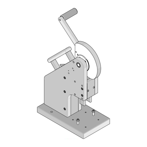
This is a small Arbor Press fixture for mounting into
the standard European Arbor Press 69020-0660.
The tooling will process Picoflex connectors in both
directions. It will process the board-in version 91577
on ribbon cable in jumper and daisy chain styles.
The connector is pushed into the holder, cable is then
inserted. The handle on the Arbor Press is then pulled
down which will complete the termination cycle.
This unit can only be used for Picoflex 91577 4 to 26
circuit.
This unit requires no electrical or pneumatic services.
If more information is required then please contact
M.A.T.E. Customer Services.
This fixture requires a standard Euro Arbor Press to
operate. Part Number 69020-0660.

AS.04.05.11/ ISSUE A
FILENAME: M-69020-1908
69020-1908 ARBOR PRESS FIXTURE - 91577
ARBOR PRESS FIXTURE
PART NO. 69020-1908
DESCRIPTION
This fixture
is used to
terminate pre-cut ribbon cable into the 91577 Picoflex connect
4 - 26 circuit
FEATURES
1. This fixture can only be used in a standard Arbor Press
part No. 69020-0660.
2. For loose piece connectors only.
3. Hand loading of connector and cable.
4. Cable Guide.
SPECIFICATION
SIZE: 155mm x 110mm x 90mm
WEIGHT: 1 kg
WORKING SERVICES: None

AS.04.05.11/ ISSUE A
FILENAME: M-69020-1908
69020-1908 ARBOR PRESS FIXTURE - 91577
2.0 SPECIFICATION
2.1 Electrical power supply - not required. Pneumatic
power supply - not required. Actuation of unit is
done using a manually pulled lever.
2.2 Unit is designed for medium to low volume production,
i.e. it has not been designed for one operator to use
continually (R.S.I. problem).
small batch production is ideal
use PB16 for large batch production.
Contact M.A.T.E. Customer Service for information.
2.3 Connector to be supplied in tubes.
2.4 Operators should undergo suitable training for this
Arbor Press.
2.5 Improper use of this tool will lead to damage of
insertion blades.
2.6 Not suitable for extreme environments i.e. very damp
or explosive atmosphere.
2.7 This unit does not exceed 70dB in normal use.
2.8 This Arbor Press will only process 91577 connectors 4
to 26 circuit.
2.9 This Arbor Press is designed for manual use only.
2.10 The orientation of the connector is the
responsibility of the operator.

AS.04.05.11/ ISSUE A
FILENAME: M-69020-1908
69020-1908 ARBOR PRESS FIXTURE - 91577
3.0 INSTALLATION
3.1 Remove Arbor Press fixture from the packing
crate. Remove all packing material.
3.2 Loosen nuts A and B. Raise platen up to allow
entry of fixture.
3.3 Place Arbor Press fixture into Euro Arbor Press
checking height is correct for fixture. See
Product Specification.
3.4 Screw Arbor Press fixture to base plate, this
will avoid it falling over or moving during
operation.
3.5 Pull handle fully down and tighten two set
screws. This will attach the upper part of the
fixture to the Mandrel.
3.6 The Arbor Press is now ready for testing.
(Height will need setting accurately).
NOTE:
1. Any adjustments must be done by a qualified engineer.
2. Test samples must be done as soon as the Arbor Press is
installed and Q.A. should do an assessment.
3. A machinery installation safety assessment checklist
must be completed before the operator can use this Arbor
Press.
See Section 11.0.

AS.04.05.11/ ISSUE A
FILENAME: M-69020-1908
69020-1908 ARBOR PRESS FIXTURE - 91577
4.0 SET UP AND OPERATION
4.1 After installing this Arbor Press, no further
setting-up is required.
4.2 Using the Arbor Press for production.
4.2.1 Check orientation of connector then
place it into the base track, slide it
to the right until it meets the end stop
screw.
4.2.2 Slide ribbon cable into connector until
the rear stop can be felt.
4.2.3 Pull handle fully down until it stops.
4.2.4 Release handle and remove harness by
sliding it to the left then pulling
straight out.
4.3 Using Arbor Press for Daisy Chain
4.3.1 First remove cable rear stop.
4.3.2 Insert connector as above.
4.3.3 Insert ribbon cable and pull through to
required position.
4.3.4 Pull handle fully down and release,
slide connector out.
4.3.5 The customer will be required to make
additional equipment to accurately
position connectors when making daisy
chain harnesses.
4.3.6 Care should be taken when making daisy
chain harnesses. The order of assembly
is very important.
This Arbor Press is not able to insert a
connector between two others.
NOTE: 1. Refer to your Q.A. Department for first-
off checks and batch production checks.
2. If adjustment is required see Section 5.0.

AS.04.05.11/ ISSUE A
FILENAME: M-69020-1908
69020-1908 ARBOR PRESS FIXTURE - 91577
5.0 ADJUSTMENTS / CONNECTOR ORIENTATION
5.1 Adjustments - First circuit leading/trailing
5.1.1 No adjustments are required between first
circuit leading or first circuit trailing.
5.2 End Stop Adjustment
5.2.1 If the connector end stop needs adjustment
then this can be done by loosening the nut
and rotating the screw to obtain a good
position. This screw is on the rear of
the fixture.
5.3 Height
5.3.1 If height adjustment is required then
this can be done by loosening the nuts
“A” and “C” also cap screw “B” (See
figure 3.2)
5.3.2 Set height using nuts “A” and “C”.
5.3.3 Cap screw “B” must always be fully
tightened before terminating.
(If not movement will take over).

AS.04.05.11/ ISSUE A
FILENAME: M-69020-1908
69020-1908 ARBOR PRESS FIXTURE - 91577
6.0 MAINTENANCE
6.1 All maintenance to be carried out by a
qualified engineer.
6.2 Clean and remove all foreign matter.
6.3 Inspect parts for damage and replace
unserviceable parts.
6.4 Lightly oil mechanical touching parts.
6.5 To check any settings, do test samples and
obtain results from Q.A.

AS.04.05.11/ ISSUE A
FILENAME: M-69020-1908
69020-1908 ARBOR PRESS FIXTURE - 91577
7.0 SPARE PARTS
NUMBER
DESCRIPTION
GROUP
GROUP
69127-5157
Insertion Blade
2
A
69127-5151
Support Plate
1
C
Refer to assembly drawing for other parts on the Arbor
Press (see section 8.0).
Group A - available Ex-stock from Molex
Group B - available on a lead time.
NOTE:
Group “A” apres must be held by customer. These are
perishable parts which will stop the machine running if
breakage or failure occurs.

AS.04.05.11/ ISSUE A
FILENAME: M-69020-1908
69020-1908 ARBOR PRESS FIXTURE - 91577
8.0 ASSEMBLY DRAWINGS
Drawing number 69020-1908 - Arbor Press Module
Drawing number 69020-1905 –Sub Assy Arbor Press Fixture
Drawing number 69020-1925 - G.A. of Die Set
OPTIONAL EXTRA
Drawing Number 69020-1935 - Assey of connector clamp.
This is a small mechanical clamp which is used to hold
the connector in place during termination.

AS.04.05.11/ ISSUE A
FILENAME: M-69020-1908
69020-1908 ARBOR PRESS FIXTURE - 91577

AS.04.05.11/ ISSUE A
FILENAME: M-69020-1908
69020-1908 ARBOR PRESS FIXTURE - 91577

AS.04.05.11/ ISSUE A
FILENAME: M-69020-1908
69020-1908 ARBOR PRESS FIXTURE - 91577

AS.04.05.11/ ISSUE A
FILENAME: M-69020-1908
69020-1908 ARBOR PRESS FIXTURE - 91577

AS.04.05.11/ ISSUE A
FILENAME: M-69020-1908
69020-1908 ARBOR PRESS FIXTURE - 91577

AS.04.05.11/ ISSUE A
FILENAME: M-69020-1908
69020-1908 ARBOR PRESS FIXTURE - 91577

AS.04.05.11/ ISSUE A
FILENAME: M-69020-1908
69020-1908 ARBOR PRESS FIXTURE - 91577
9.0 FAULT FINDING
9.1 Bad Termination
9.2 Inconsistent termination heights.
9.3 Die set not functioning.
9.4 Inconsistent bad terminations.
9.1 Bad Terminations
9.1.1 Check lever is pulled fully down before
it comes up again.
9.1.2 Check connector is pushed up to end stop
properly before handle is pulled..
9.1.3 Check cable is inserted fully before
handle is pulled.
9.1.4 Check ends of cable are cut square to
axis of cable.
9.1.5 (90584 connector) Check all legs are
vertical and do not show any sign of
transportation damage.
9.2 Inconsistent Termination Heights.
9.2.1 Check blades for damage or wear.
9.2.2 Check cable circuit size is correct for
connector.
9.2.3 Check for movement within the die set
i.e. long term wear.
9.3 Die Set not working
9.3.1 Check blade alignment. It may be
hitting the connector holder block.
9.3.2 Check no parts have moved out of
position.
9.3.3 Bearings may have seized, remove and
replace.
9.3.4 Ratchet in Arbor Press may have jammed.

AS.04.05.11/ ISSUE A
FILENAME: M-69020-1908
69020-1908 ARBOR PRESS FIXTURE - 91577
9.4 Inconsistent bad termination.
9.4.1 These are normally caused by the operator.
Check and review process that the operator
is using, looking for “bad use” problems.

AS.04.05.11/ ISSUE A
FILENAME: M-69020-1908
69020-1908 ARBOR PRESS FIXTURE - 91577
10.0 SPC / QUALITY
10.1 A capability study has been done on this Arbor
Press.
Copies of results can be obtained from
M.A.T.E. Customer Service if required.
10.2 The Molex minimum requirement for Cpk is 1.66.
This unit therefore exceeds this figure.
10.3 When using this Arbor Press always:
i. Q.A samples on installation to ensure
they meet your specifications and Molex
specifications.
ii. Q.A first off samples at the start of
each batch
iii. Q.A after any changes or adjustments to
Arbor Press or Die set.
iv. Q.A samples with new operator.
v. Q.A samples if Arbor Press is moved.

AS.04.05.11/ ISSUE A
FILENAME: M-69020-1908
69020-1908 ARBOR PRESS FIXTURE - 91577
11.0 MACHINERY INSTALLATION SAFETY ASSESSMENT
CHECKLIST
11.1 The following eleven pages must be used after
installation of the new electric powered hand
tool unit.
If these sheets are not used then your own
company approved installation assessment system
must be used.
11.2 It is the responsibility of a company to ensure
the safety of it’s work staff.
11.3 This assessment will enable your company to
highlight any problems errors or misgivings
that may or may not effect your employees.
11.4 NOTE:
It will be your company’s responsibility to
install suitable guards and do a risk
assessment for operator safety.
11.5 Please check suitable guarding has been
supplied with this unit or any change heads
supplied. Contact M.A.T.E. Customer Service if
you have any problems.
11.6 Risk assessment records must be kept by each
company.
11.7 The eleven sheets can be found by down loading
file number m-69095-1000 from the Molex
internet, intranet or Midas web.
11.8 If you are unable to obtain the information
required then contact M.A.T.E. customer
service.
Table of contents
Other molex Power Tools manuals

molex
molex 63801-8550 User manual

molex
molex 69020-2025 User manual

molex
molex Mini Mi2 User manual

molex
molex RHT 2251 User manual

molex
molex TM-3000 User manual

molex
molex TM2000 User manual

molex
molex 63816-0100 Manual

molex
molex 69020-0660 User manual
molex
molex 63823-5600 User manual

molex
molex 63816-1700 User manual

molex
molex 63600-0478 User manual
molex
molex TM-3000 User manual

molex
molex VHDCI User manual

molex
molex 63827-2000 User manual
molex
molex TM42 User manual

molex
molex 63819-7300 User manual

molex
molex TM-3000 User manual

molex
molex 63823-3900 User manual

molex
molex 19286-1000 User manual

molex
molex 63811-0300 User manual