Reeve UPC-590L-M Guide

UPC-590L-M Up-Converter Installation and Operation
See last page for copyright and document information, File: Reeve_UPC59 _Instructions.docx, Page 1
1. Description
The model UPC-59 L-M consists of two identical heterodyne converters with 5 to 85 MHz RF input and 2 5 to
285 MHz IF output. It is designed for use with the Long Wavelength Array (LWA) Antenna and includes 15 dB of
attenuation in each IF output path. The UPC-59 L-M has the same dimensions and form factor as the LWA
Power Coupler and Callisto instruments. Because the LWA Antenna has built-in front-end electronics with low
noise figure and high gain, the UPC-59 L-M has no RF input preamplification.
The UPC-59 L-M panel layouts are shown below. The front panel (left) has connectors for power (2.1 x 5.5 mm
coaxial jack, center positive), a power switch and power indicator and two output connectors for the IF to the
receivers (type N-female). The rear panel (right) has two input connectors for the RF from the LWA Power
Coupler (type N-female).
The basic configuration is shown below. The Converter is inserted between the LWA Power Coupler and the
Callistos instrument or other receivers.

UPC-590L-M Up-Converter Installation and Operation
See last page for copyright and document information, File: Reeve_UPC59 _Instructions.docx, Page 2
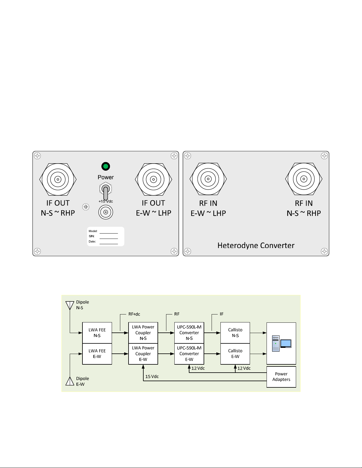
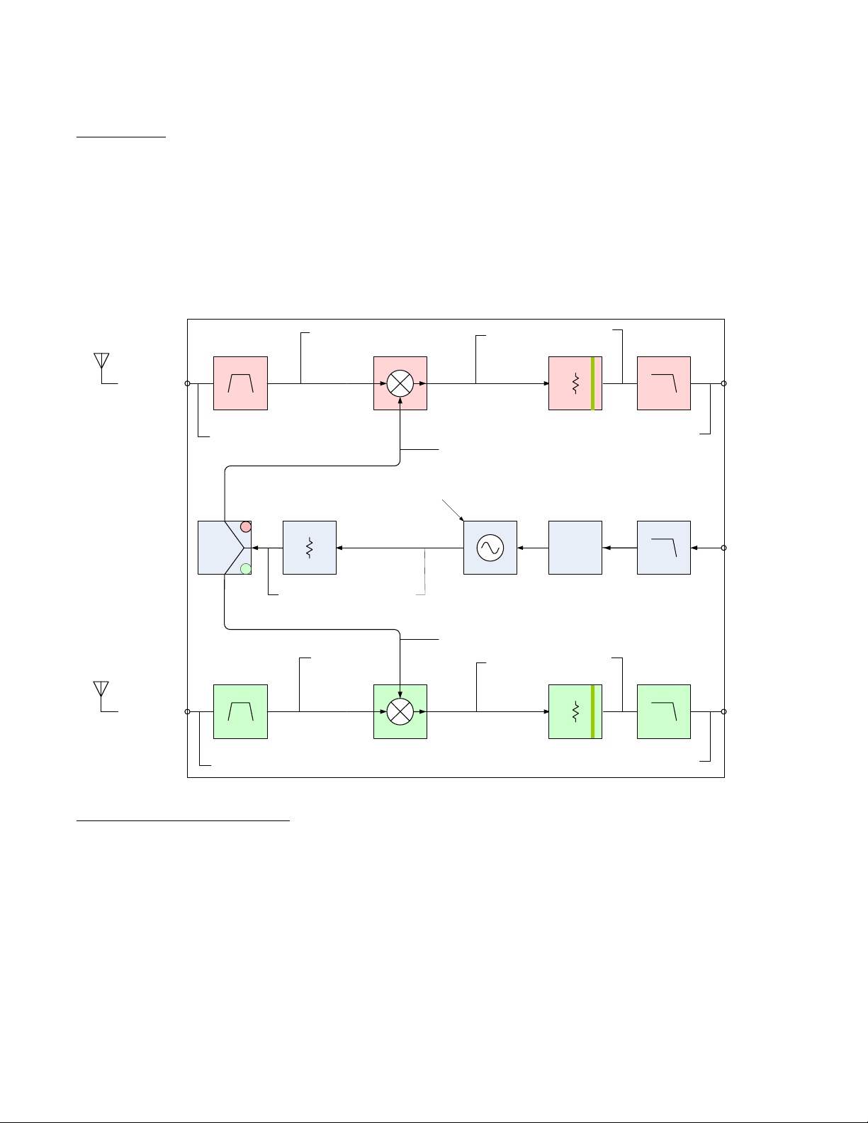
2. Installation
Equipment location
The Converter should be placed in an indoor environmentally controlled location with a reliable source of
power. It is recommended that the Converter be collocated with the Callisto instrument and connected to it
with a short coaxial jumper cable.
Signal levels
The LWA Antenna is an active antenna. The Front-End Electronics (FEE) gain is 35 dB. The UPC-59 L-M has a 15
dB attenuator in the IF output path and its mixer has a conversion loss of approximately 6 dB. Internal filters,
coaxial cables and connectors introduce approximately 1 dB of additional loss, giving a total loss of 22 dB
through the converter. To maintain a dB Transmission Level Point at the RF input to the Callisto instrument or
other receiver, additional attenuation will need to be inserted in the RF circuit between the LWA Power Coupler
and the receiver. The value of this attenuator will depend on the additional losses introduced by external coaxial
cables and splitters (if equipped). Ordinary RF circuit engineering principles can be used to determine these
losses.
Power supply
The UPC-59 L-M requires 12 Vdc input voltage. Nominal load current is 1 mA. The power supply should be
regulated such that the voltage at the UPC-59 L-M power input connector never drops below 8 V under all
anticipated input and output conditions. The power supply should be high quality. It is recommended that
ferrite beads be placed on the power supply lead at both the Converter end and power supply end. Clamshell
beads will allow several windings of the power leads to be wrapped around the cores.
Coaxial cable transmission lines and connectors
Coaxial cables can build up a static charge that, if allowed to discharge by connecting to equipment, may
damage sensitive input circuits. To avoid such damage, it is recommended that static charges be dissipated by
momentarily shorting the cable connector center pin and shield before connecting to the converter. This should
be done carefully to avoid damaging the connector center pin. Also, all coaxial cable connections must be made
before power is applied to any of the components.
All coaxial cables and connectors used with the UPC-59 L-M converter must be 5 ohms impedance.
The LWA Antenna requires a power coupler (for example, the LWAPC or LWAPC-Q) and has a built-in
preamplifier called Front End Electronics (FEE). The coaxial cable that connects the LWA Antenna FEE to the
power coupler may be 5 or 6 mm diameter and its length is not critical within reasonable limits. Refer to the
LWA Antenna and LWA Power Coupler documentation for specific details on installing those components.
The coaxial cable that connects the LWA Power Coupler to the UPC-59 L-M Converter generally should be 5 to
1 mm diameter and ≤ 5 m long. If a longer cable is required, an intermediate amplifier may be needed.
Similarly, the cable between the UPC-59 L-M Converter and Callisto instrument or receiver should be 5 to 1
mm diameter and ≤ 5 m long, and an intermediate amplifier used with longer cables. Use only the best possible
quality RF connectors and cables.

UPC-590L-M Up-Converter Installation and Operation
See last page for copyright and document information, File: Reeve_UPC59 _Instructions.docx, Page 3
3. So tware Setup
Before attempting to setup the Converter, refer to the Callisto Software Setup Guide for detailed instructions on
using the Callisto software and the Frequency Genie software tool. Setup the UPC-59 L-M Converter according
to the steps below, while referring to the screenshots immediately following:
1. Connect all equipment; double-check all coaxial cable and power connections and power supply
voltages. Refer to the LWA Antenna and LWA Power Coupler instruction manuals for connection and
powering details;
2. Apply power to LWA Power Coupler, UPC-59 L-M Converter, and Callisto instrument;
3. Open callisto.exe and obtain a spectral overview (OVS) of the sky. This records the relative sky noise
power at each frequency within Callisto’s frequency range 45 to 87 MHz with 62.5 kHz resolution. This
range includes frequencies within the up-converter IF output range and also includes frequencies
outside the range. When finished with this step close callisto.exe;
4. Open the Frequency Genie software tool and load the spectral overview from step 3;
5. For the UPC-59 up-converter, setup Frequency Genie as follows:
Channel selection method: Minimum detection (see Note)
Type of converter: Upconverter (IF=RF+LO)
Sweeplength: 2
RF Startfrequency (MHz): 5
RF Stopfrequency (MHZ): 85
LO (converter)(MHz): 2
Filenumber FRQxxxxx.cfg: to 99999 (example, 585)
Note: To prepare a frequency list based only on equal spacing of the channels, select Equally Spaced;
however, strong radio frequency interference (RFI) may exist on some channels and the frequency
list with equal spacing may require manual editing.
6. To view the frequency range on the Spectral Overview, click the Preview FrqPrg button on lower-right of
the Frequency Genie main window. The programmed frequency range will be shown as a green slanted
line;
7. Click the Save Program button on the upper-right of the main window to generate the frequency list;
8. Move or copy the frequency list file to the same folder as callisto.exe;
9. Edit callisto.cfg parameter [frqfile] to use the frequency file from step 7. It may be necessary to reduce
the Callisto gain parameter [agclevel] due to the gain of the LWA FEE. A new setting will have to be
found experimentally. See section 2. Installation – Signal levels for additional information.

UPC-590L-M Up-Converter Installation and Operation
See last page for copyright and document information, File: Reeve_UPC59 _Instructions.docx, Page 4
1 . Change the focus code parameter [focuscode] in callisto.cfg. The recommended code is 62 for right-
hand circular polarization (RHCP) and 63 for left-hand circular polarization (LHCP). When the LWA
Antenna is configured for linear polarizations, the recommended focus codes are 58 and 59. The focus
code number is not critical but must be different for each polarization;
1 . Edit scheduler.cfg for the desired observing schedule;
11. Open callisto.exe. It will automatically load the new frequency file;
12. If callisto.cfg is not setup for automatic execution, manually start the new observation. When the
Automatic radio button is selected, Callisto will observe according to the scheduler.cfg file setup in step
1 ;
13. On the callisto.exe main window, click on Spectrum y(f) to view the spectrum of the programmed
frequency range.
Frequency Genie
main window
showing setup for
an up-converter
with 2 MHz LO
and 5 to 85 MHz
RF input. The
output filename
(Filenumber) is
585.

UPC-590L-M Up-Converter Installation and Operation
See last page for copyright and document information, File: Reeve_UPC59 _Instructions.docx, Page 5
Part of an example frequency list generated by
Frequency Genie with 2 channels per sweep, 4
sweeps per second, frequency range 5 to 85 MHz and
local oscillator of 2 MHz. Note: The start frequency is
repeated five times to allow the tuner synthesizer to
stabilize when starting a new sweep. The amount of
repetition is set by the
[nonlinchans]
parameter in
params.cfg
file of the Frequency Genie.
Spectrum plot from
Frequency Genie showing
spectrum for the OVS. The
slanted green line is the
programmed frequency
range of the receiver RF
input/up-converter IF
output.
Spectrum Y(f) plot from callisto.exe showing
the frequency range 5 to 85 MHz for the
UPC-59 L-M up-converter with no signal
input. This plot was made with a 5 ohm
termination on the RF input.

UPC-590L-M Up-Converter Installation and Operation
See last page for copyright and document information, File: Reeve_UPC59 _Instructions.docx, Page 6
4. UPC-590L-M Up-Converter Description
Block diagram
The UPC-59 L-M up-converter consists of two identical assemblies that share a common local oscillator. The
following describes one of the assemblies. The RF input is first applied to a 5 to 85 MHz bandpass filter and then
to the double-balanced mixer. A 2 MHz local oscillator is mixed with the filtered RF input to provide an IF
output range of 2 5 to 285 MHz. The mixer conversion loss is approximately 8 dB. The mixer IF output is applied
to a 2 dB attenuator and lowpass filter with a corner frequency of 32 MHz. The lowpass filter reduces the 2
nd
and higher harmonics of the oscillator leakage through the mixer. A power supply printed circuit board (model
CPS-3) uses a linear low noise, low dropout voltage regulator to provide regulated 5. Vdc to the oscillator.
Specifications (all values nominal)
•Architecture: Single stage heterodyne converter
•Configuration: Dual converters with common local oscillator
•RF input frequency range: 5 to 85 MHz
•RF input connector: Type N-female
•IF output frequency range: 2 5 to 285 MHz
•IF output connector: Type N-female
•Input voltage: 12 Vdc
•Input current: 12 mA maximum
•Input power connector: 2.1x5.5 mm coaxial jack (center positive +)
•Gain: –22 dB (with internal 2 dB attenuator in each channel)
•Dimensions: 168 mm long x 11 mm wide x 79 mm high
LO
Mixer
RF Input
from LWAPC
N-S ~ RHCP
IFRF
Up-Converter
UPC-59 M
BPF
LO LPF
CPS-2
Power
Supply
Power Input
(12 Vdc)
IF Output to
CALLISTO
Receiver RHCP
Reeve
FL59
MCL
ZX 5-1L-S+
5...85 MHz
Si53 : 2 MHz
VCO+(5~8 )
MHz
Vcc
Nominal converter gain:
BPF: – .5 (– .2)
AMP: + .
MXR: –6.2
LPF: – .5 (– .2)
ATTN: -15.
Other: – .8 (– .6)
Total = –23. dB (–22.2 actual) +9. dBm
2 MHz
LO
Mixer
RF Input
from LWAPC
E-W ~ LHCP
IFRF
BPF
IF Output to
CALLISTO
Receiver LHCP
Reeve
FL59
MCL
ZX1 -2-2 -S+
5...85 MHz
MCL
ZX 5-1L-S+
MCL
SLP-32 +
Fc= 32 MHz
Fc= 32 MHz
MCL
SLP-32 +
S
F
S
F
S
F
S
F
S
F
S
F
S
M
S
F
S
F
S
F
S
F
S
F
S
F
S
F
S
F
S
F
S
M
SMA-F-RA-BKHD:N-F-BKHD
160 mm RG-316
SMA-M-RA:SMA-M-ST
150 mm RG-316
SMA-M-RA:SMA-M-RA
150 mm RG-316
N-F-BKHD:SMA-M-RA
150 mm RG-316
N-F-BKHD:SMA-M-RA
150 mm RG-316
SMA-M-RA:SMA-M-RA
150 mm SMA-M-RA:SMA-M-ST
150 mm RG-316
SMA-F-RA-BkHD:N-F-BKHD
160 mm RG-316
SMA-M-RA:SMA-M-RA
150 mm RG-316
SMA-M-RA:SMA-M-RA
150 mm RG-316
S
F
SMA-M-ST:SMA-M-RA
150 mm RG-316
VCO+(5~8 )
MHz
–2. dB
S
M
S
F
Direct Connect
5. V
-3.8 dB
1 9 mA
5...85 MHz
5...85 MHz 2 5...285 MHz
2 MHz
2 MHz
+3. dBm
LWA
Antenna
TLP=+35 dB
TLP=+13 dB
S
F
S
M
–15 dB
Direct Connect
–15 dB
S
F
S
M
Direct Connect
Splitter
MCL
VAT-15+
MCL
VAT-15+
VAT-2+
2 MHz

UPC-590L-M Up-Converter Installation and Operation
See last page for copyright and document information, File: Reeve_UPC59 _Instructions.docx, Page 7
•Weight: 3.8 kg
5. Operation and Maintenance
Operation:
All RF connections should be made to the Converter and Receiver before the power supply is connected and
turned on. Power is applied by toggling the power switch on the front panel to the UP position. Power is
removed by toggling the power switch to the DOWN position.
IMPORTANT: After the Converter has been in operation and if the coaxial cables need to be disconnected, the
power switch should be turned off and the power cable removed before disconnecting the coaxial cables. If the
Converter is used with the LWA Power Coupler (LWAPC), follow the instructions associated with the power
coupler before applying or removing power from either unit.
Maintenance:
The Converter requires very little periodic maintenance. Converter maintenance described below should be
performed when performing regular maintenance on the Callisto instrument, other receiver or power coupler.
A. Monthly Preventative Maintenance
☼
Brush dust off the instrument being careful to not disturb the connections
☼
If additional cleaning of the enclosure and panels is required, use a damp cloth; DO NOT use any
chemicals (or else the silkscreen may dissolve)
☼
Check condition of all cables and connectors
B. Annual Preventative Maintenance
☼
Check power supply voltage, 12 Vdc
☼
Check local oscillator frequency, 2 MHz
±
2 kHz (measure at IF Output with a frequency counter)
after > 2 h warmup. The oscillator is not tunable; it is recommended that the unit be returned to the
factory if the LO frequency is out of specification.
C. Internal RF connectors
If the internal type SMA RF connectors are loose or removed and replaced, torque them to 45 N-cm (4
in-lb).

UPC-590L-M Up-Converter Installation and Operation
See last page for copyright and document information, File: Reeve_UPC59 _Instructions.docx, Page 8
Document in ormation
Author: Whitham D. Reeve
Copyright: © 2 22 W. Reeve
Revision: . (Original draft started, 19 Dec 2 2 )
.1 (Updated block diagrams, 19 Sep 2 21)
.2 (Highlighted images to be replaced, 21 Sep 2 21)
.3 (Updated IF frequencies to match -M oscillator, 27 Jan 2 22)
.4 (Replaced all images with current, 28 Jan 2 22)
Table of contents
Other Reeve Media Converter manuals
Popular Media Converter manuals by other brands

RDS
RDS P332 Technical manual

gofanco
gofanco HDMI2DP-2P user guide

Pro-Ject Audio Systems
Pro-Ject Audio Systems DAC Box E mobile Instructions for use

Linear Technology
Linear Technology DC2283A Demo Manual

Patton electronics
Patton electronics 2021P Installation and operation manual

ANTAIRA
ANTAIRA FCU-280 Series user manual

CES
CES ARi-51 installation instructions

SICK STEGMANN
SICK STEGMANN SES70 quick start guide

Speaka Professional
Speaka Professional 1404113 Operating intructions

Cambridge Audio
Cambridge Audio Upsampling Digital to Analog Converter azur... user manual

Massoth
Massoth eMOTION 8FS manual

exemys
exemys EGW1-IA3-MB-DF1 user manual