INTRODUCTION 2
STARTING RECOMMENDATIONS
INDEX
First of all we would like to thank and congratulate you for the purchase of this product manufactured by
The commitment to reach the satisfaction of our customers is stated through the ISO-9001 certification
and for the manufacturing of products like this one.
Its advanced technology and exacting quality control will do that customers and users enjoy with the
legion of features this system offers To obtain the maximum profit of these features and a properly wired
installation, we kindly recommend you to expend a few minutes of your time to read this manual.
Golmar.
.
O
O
O
O
O
O
The installation and handling of this equipment must be performed by authorised personnel
Install or modify the equipment without the power connected
Do not use excessive force when tightening the converter connection block screws
Before connecting the system, check the connections between door panel, converter, distributor,
monitors, telephones and the power supply connection.
When starting the equipment for the first time, or after a modification, the system will remain inactive
for around 45 seconds due to the initial busy channel time
.
O.
.
The entire installation must be at least 40 cm. away from any other installation.
.
Do always follow the enclosed information.
Introduction........................................................................................................................2
Index .................................................................................................................................2
Starting recommendations....................................................................................................2
Safety precautions ...............................................................................................................3
System characteristics ..........................................................................................................3
Operation modes ..........................................................................................................3-4
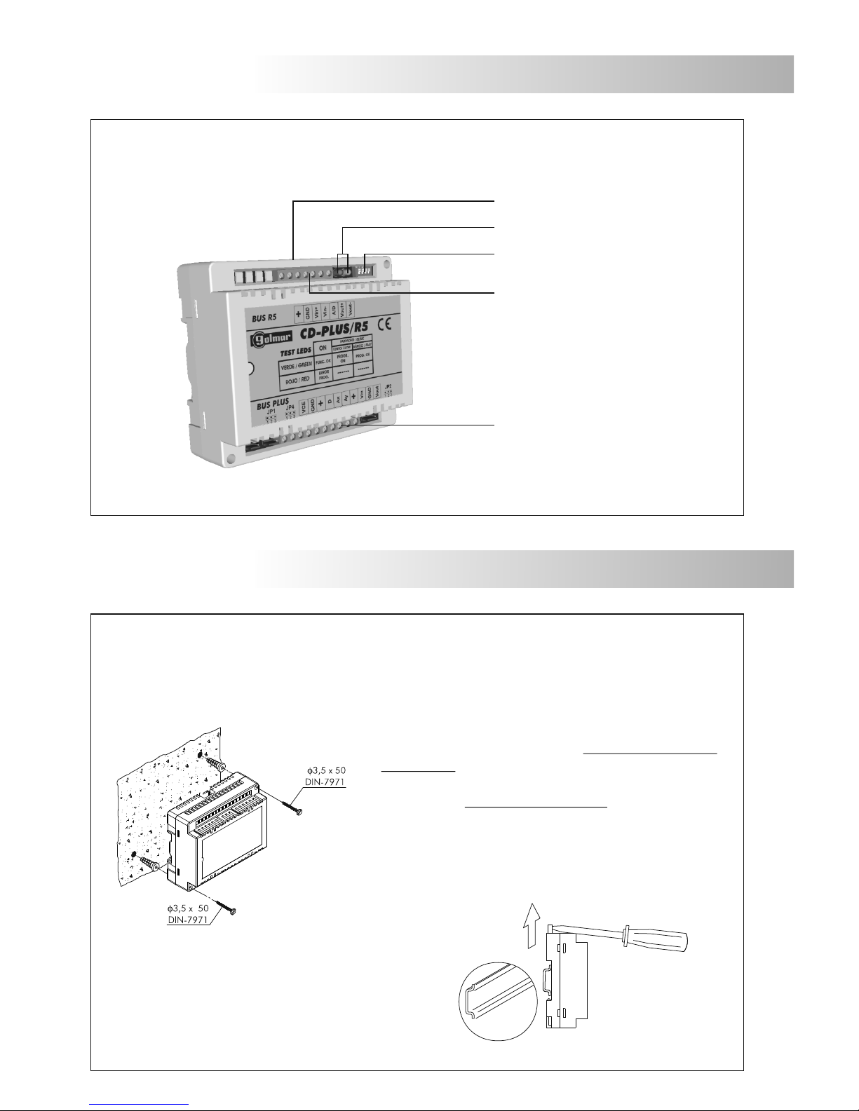
Description.........................................................................................................................5
Installation .........................................................................................................................5
.............................................................................................................6
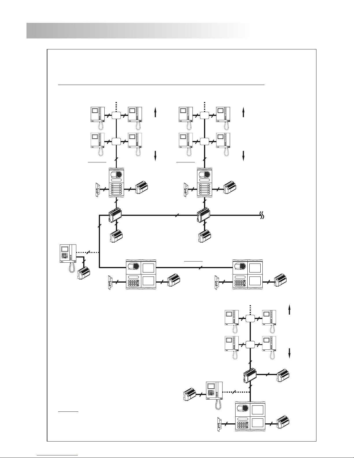
Installation diagrams .............................................................................................................
Porter's exchange interface mode with D4L-R5 distributor .......................................................8
Porter's exchange interface mode with D4L-R5R distributor......................................................9
Backbone encoder mode (general door panels) ...............................................................10-11
Backbone encoder mode (coded panel) with D4L-R5 distributor..............................................12
Backbone encoder mode (coded panel) with D4L-R5R distributor............................................13
Troubleshooting hints......................................................................................................14-15
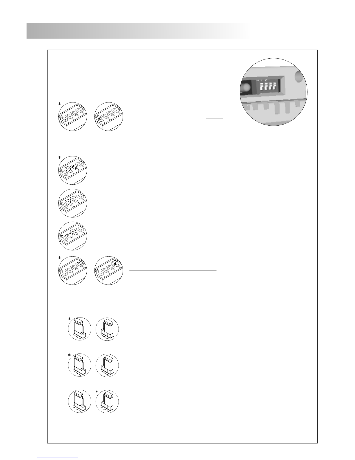
Configuration dip switch.......................................................................................................6
Configuration jumper (End of line resistor) ..............................................................................6
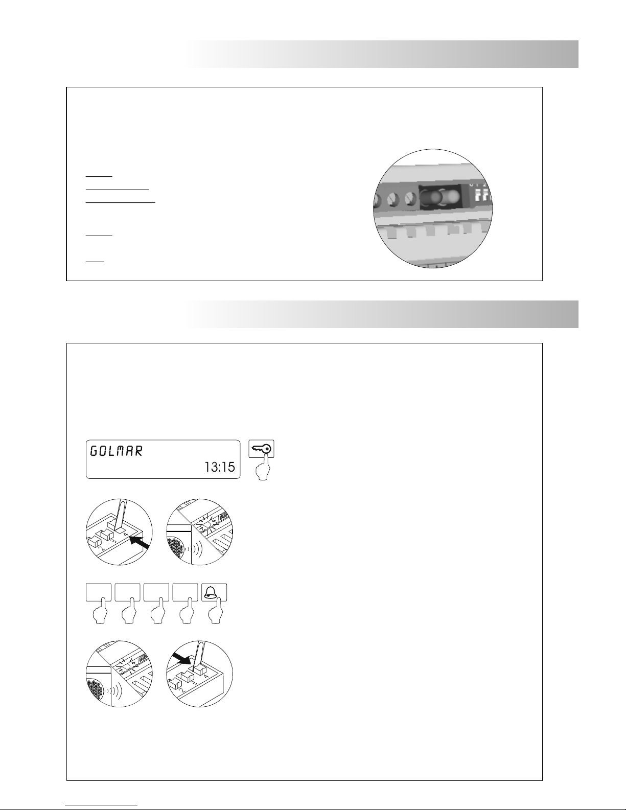
rogramming the converter
Autodiagnostic Leds
P (Backbone code) ..........................................................................7