Reeve UPC-1 Owner's manual

UPC-1 Up-Converter Installation and Operation
See last page for copyright and document information, File: Reeve_ConverterInstructions.doc, Page 1
1. Description
he model UPC-1 is a heterodyne converter with 20 to 90 MHz RF input and 220 to 290 MHz IF output. It uses
high-quality commercial RF modules and has internal regulated power supplies. he UPC-1 has the same form
factor and is designed to be used with the Callisto instrument. Converters that are to be used with the LWA
Antenna are factory modified to reduce the converter gain. hese factory modifications are reversible as
described in Appendix I. he factory modifications themselves are described in Appendix II.
he UPC-1 panel layouts are shown below. he front panel (left) has input connectors for power (2.1 x 5.5 mm
coaxial jack) and RF from the antenna system (type N-female) and a power switch and power indicator. he rear
panel (right) has an output connector for the IF to the receiver (type N-female).
Model:
S/N:
Date:
ON
Power
+15 Vdc
RF IN
e-CALLIS O-NA
Anchorage, Alaska USA
IF OU
Heterodyne Converter
he basic configuration is shown below. he up-converter provides approximately 16 dB conversion gain. A low
noise preamplifier near the antenna (tower-mounted amplifier, MA) will improve system sensitivity. he MA-1
or MA-2 tower-mounted amplifiers may be used with the UPC-1 up-converter (all MAs are tested from 10
MHz to 1 GHz). he Converter is inserted between the LNA power coupler or bias-tee and the Callisto
instrument.
Callisto
Callisto
Antenna
Converter
IF
RF+dc
Tower-
Mounted
Amplifier
Power
Adapters
15 Vdc
12 Vdc
LNA Power
Coupler
RF

UPC-1 Up-Converter Installation and Operation
See last page for copyright and document information, File: Reeve_ConverterInstructions.doc, Page 2
2. Installation
Equipment location
he Converter should be placed in an indoor environmentally controlled location with a reliable source of
power. It is recommended that the Converter be collocated with the Callisto instrument and connected to it
with a short coaxial jumper cable.
Power supply
he UPC-1 requires 15 to 17 Vdc input voltage. he power supply ac adapter should be regulated such that the
input never drops below 15 V under all anticipated input and output conditions. he power supply should be
high quality and electrically quiet with low ripple. It is recommended that ferrite beads be placed on the power
supply lead at both the Converter end and power supply end. Clamshell beads will allow several windings of the
power leads to be wrapped around the cores.
It is recommended that the power supply be rated 200 mA. he power supply output voltage (Converter input
voltage) must be high enough to provide 15.0 Vdc at the Converter.
Coaxial cable transmission lines and connectors
Coaxial cables can build up a static charge that, if allowed to discharge by connecting to equipment, may
damage sensitive input circuits. o avoid such damage, it is recommended that static charges be dissipated by
momentarily shorting the cable connector center pin and shield before connecting to the converter. his should
be done carefully to avoid damaging the connector center pin.
All coaxial cables and connectors used with the UPC-1 converter must be 50 ohms impedance.
he LWA Antenna may be used with the UPC-1 converter. he LWA Antenna requires a power coupler (for
example, the LWAPC or LWAPC-Q) and has a built-in preamplifier called Front End Electronics (FEE). he FEE has
2.7 dB noise figure and 35 dB gain. he coaxial cable that connects the LWA Antenna FEE to the power coupler
may be 5 or 6 mm diameter and its length is not critical within reasonable limits. See LWA Antenna
documentation for specific details on installing the LWA Antenna. he coaxial cable that connects the LWA
Antenna power coupler to the UPC-1 generally should be ≥ 10 mm diameter and ≤ 50 m long.
For systems that do not use the LWA Antenna, the system noise figure is primarily established by the low noise
preamplifier located near the antenna. Each 1 dB of cable loss between the antenna and a nearby low noise
amplifier increases the system noise figure by 1 dB. herefore, the cable and RF connectors between the
antenna and the low noise amplifier must be of the best possible quality and as short as possible.
he cable between the antenna and Converter should be ≥ 10 mm diameter and ≤ 50 m long. If a longer cable is
required, an intermediate amplifier with 10 to 15 dB gain should be placed at the output of the MA. Similarly,
the cable between the Converter and Callisto should be ≥ 10 mm diameter and ≤ 50 m long, and an intermediate
amplifier used with longer cables. Use only the best possible quality RF connectors and cables.

UPC-1 Up-Converter Installation and Operation
See last page for copyright and document information, File: Reeve_ConverterInstructions.doc, Page 3
3. Software Setup
Before attempting to setup the Converter, refer to the Callisto Software Setup Guide for detailed instructions on
using the Callisto software and the Frequency Genie software tool. Setup the Converter according to the steps
below, while referring to the screenshots immediately following.
1. Connect all equipment; double-check all RF and power connections and power supply voltages
2. Apply power to Converter, Callisto and preamplifiers ( ower Mounted Amplifier). If the LWA Antenna is
used, refer to the LWA Antenna instruction manual for connection and powering details.
3. Open callisto.exe and obtain a spectral overview (OVS) of the sky. his records the sky noise power at
each frequency within Callisto’s frequency range 45 to 870 MHz with 62.5 kHz resolution. his range
includes frequencies within the up-converter IF output range. When finished with this step close
callisto.exe
4. Open the Frequency Genie software tool and load the spectral overview from step 3
5. For the UPC-1 up-converter, setup Frequency Genie as follows.
Channel selection method: Minimum detection (see note)
ype of converter: Upconverter (IF=RF+LO)
Sweeplength: 200
RF Startfrequency (MHz): 20
RF Stopfrequency (MHZ): 90
LO (converter)(MHz): 200
Filenumber FRQxxxxx.cfg: 00000 to 99999 (example, 00020)
Note: o prepare a frequency list based only on equal spacing of the channels, select Equally Spaced;
however, strong radio frequency interference (RFI) may exist on some channels and the frequency
list with equal spacing may require manual editing.
6. o view the frequency range on the Spectral Overview, click the Preview FrqPrg button on lower-right of
the Frequency Genie main window. he programmed frequency range will be shown as a green slanted
line
7. Click the Save Program button on the upper-right of the main window to generate the frequency list
8. Move or copy the frequency list file to the same folder as callisto.exe
9. Edit callisto.cfg parameter [frqfile] to use the frequency file from step 7. It may be necessary to reduce
the Callisto gain parameter [agclevel] due to the gain of the up-converter. A new setting will have to be
found experimentally and will depend on whether or not a preamplifier is used. Finally, change the focus
code parameter [focuscode]; suggested code is 58.

UPC-1 Up-Converter Installation and Operation
See last page for copyright and document information, File: Reeve_ConverterInstructions.doc, Page 4
10. Edit scheduler.cfg for the desired observing schedule
11. Open callisto.exe. It will automatically load the new frequency file
12. If callisto.cfg is not setup for automatic execution, manually start the new observation. When the
Automatic radio button is selected, Callisto will observe according to the scheduler.cfg file setup in step
10
13. On the callisto.exe main window, click on Spectrum y(f) to view the spectrum of the programmed
frequency range
Frequency Genie
main window
showing setup for an
up-converter with
200 MHz LO and 20
to 90 MHz RF input
Spectrum plot from
Frequency Genie
showing spectrum
for the OVS. he
slanted green line is
the programmed
frequency range. he
spikes are LO leakage
outside the
programmed
frequency range.

UPC-1 Up-Converter Installation and Operation
See last page for copyright and document information, File: Reeve_ConverterInstructions.doc, Page 5
Spectrum Y(f) plot from callisto.exe
showing the frequency range 20 to
90 MHz for the UPC-1 up-converter
with no signal input
Part of an example frequency list generated
by Frequency Genie with 200
channels/sweep between 20 and 90 MHz and
local oscillator of 200 MHz

UPC-1 Up-Converter Installation and Operation
See last page for copyright and document information, File: Reeve_ConverterInstructions.doc, Page 6
. UPC-1 Up-Converter Description
Block diagram
Refer to block diagram below. he RF input is first applied to a 20 to 90 MHz bandpass filter and then amplified
approximately 22 dB by a low noise amplifier (typical noise figure 2.9 dB). A voltage controlled oscillator (VCO),
tuned to 200 MHz, is mixed with the filtered RF input to provide an IF output range of 220 to 290 MHz. he
mixer conversion loss is approximately 6 dB. Calculated and measured conversion gain is 16 ±0.5 dB across the
band. he VCO may be adjusted to any frequency within the range of approximately 160 to 350 MHz, and the IF
output will change accordingly (it is recommended that the VCO not be adjusted from its original setting of 200
MHz). A universal power supply printed circuit board (model CPS-1) uses linear low noise, low dropout voltage
regulators and allows a variety of amplifiers and voltage controlled oscillators to be used in this and other
converters. he variable supply for tuning the VCO is set to a nominal 3.695 V; the actual setting varies slightly
among different VCO modules. R2 on CPS-1 is used to adjust the LO frequency.
LO
Mixer
RF Input
IFRF
Up-Converter
UPC-1
BPF
VCO
LPF
CPS-1
Power Supply
+V1 Bus
Power Input
(15 Vdc)
IF Output to
CALLISTO
Receiver
Amplifier
+Vv Bus
+V2 Bus
AEL
MW-1120-85
MCL
ZX60-3018G+
MCL
ZLW-1W+
22.5 dB
20...90 MHz
MCL
ZX95-310A+
~3.6 V
200 MHz
220...290
MHz
V1
V2
Nominal converter gain:
BPF: –0.5
AMP: +22.5
MXR: –5.6
Total = +16.4 dB
CPS-1 power supply PCB

UPC-1 Up-Converter Installation and Operation
See last page for copyright and document information, File: Reeve_ConverterInstructions.doc, Page 7
Specifications (all values nominal)
•RF input frequency range: 20 to 90 MHz
•RF input connector: ype N-female
•IF output frequency range: 220 to 290 MHz
•IF output connector: ype N-female
•Input voltage: 15 ... 17 Vdc
•Input current: 100 mA maximum
•Input power connector: 2.1x5.5 mm coaxial jack (center positive +)
•Gain: 16 dB
•Dimensions: 168 mm long x 110 mm wide x 79 mm high
•Weight: 1 kg
5. Operation and Maintenance
Operation:
All RF connections should be made to the Converter and receiver before the power supply is connected and
turned on. Power is applied by toggling the power switch on the front panel to the UP position. Power is
removed by moving the toggle to the DOWN position.
After the Converter has been in operation and if the coaxial cables need to be disconnected, the power switch
should be turned off before disconnecting the coaxial cables.
Maintenance:
he Converter requires very little periodic maintenance. Converter maintenance described below should be
performed when performing regular maintenance on the Callisto instrument as described in the Maintenance
section in the Callisto Construction Manual.
A. Monthly Preventative Maintenance
☼
Brush dust off the instrument being careful to not disturb the connections
☼
If additional cleaning of the enclosure and panels is required, use a damp cloth; DO NO use any
chemicals (or else the silkscreen may dissolve)
☼
Check condition of all cables and connectors
B. Annual Preventative Maintenance
☼
Check power supply voltage, 15 ... 17 Vdc
☼
Check local oscillator frequency, 200
±
30 kHz (measure at IF Output with a frequency counter) after >
2 h warmup. Do not adjust the LO unless it is out of tolerance. o adjust, remove the top cover and
slowly turn R2 on the power supply PCB, CW to increase frequency and CCW to decrease frequency.
he VCO tuning voltage power supply has a long time constant; adjust the frequency in very small
increments and wait for the frequency to stabilize before adjusting again.
C. Internal RF connectors
If internal RF connectors are loose or removed and replaced, torque them to 45 N-cm (4 in-lb).

UPC-1 Up-Converter Installation and Operation
See last page for copyright and document information, File: Reeve_ConverterInstructions.doc, Page 8
Appendix I ~ Restore Modified UPC-1 Converter
he unmodified UPC-1 converter has an internal low noise amplifier and provides approximately +16 dB
conversion gain. he LWA Antenna is an active antenna with 35 dB gain and 2.7 dB noise figure. herefore,
when the LWA Antenna is used with the UPC-1 and Callisto instrument, the internal amplifier in the UPC-1 is
not required and the IF Output level must be reduced.
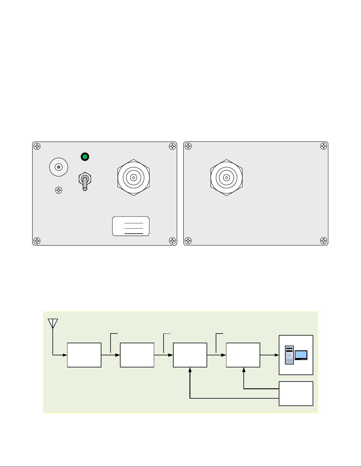
Factory modifications include disconnection of the UPC-1 internal amplifier (both RF and power) and insertion
of a 20 dB attenuator in series with the IF Output. hese modifications are made in the factory prior to
shipment when it is known that the UPC-1 will be used with the LWA Antenna. Modified units are labeled
“Modified for LWA Antenna”. he modifications are done in such a way that they are easily reversible. he
coaxial cables are left connected to the amplifier and the two conductors with socket terminal contacts for
amplifier power are removed from the power supply connector.
he following steps are required to reverse the modifications:
1.
Remove the UPC-1 top clamshell cover by removing the four screws in the upper corners of the two
end panels. Set the cover and screws aside;
2.
Remove the coaxial cable between the Mixer IF port and the Attenuator. Also remove the Attenuator
and SMA-F coupler (female-female adapter) from the IF Output cable. he cable, Attenuator and
adapter are no longer needed;
3.
Remove the IF Output end panel by removing the two screws in the lower corners. Set the end panel
and screws aside;
4.
Remove the coaxial cable between the Filter output port (this is the port closest to the IF Output end
panel) and the Mixer RF port. he cable is no longer needed;
5.
Connect the cable on the IF Output connector to the IF port on the Mixer. orque the connection;
6.
Replace the IF Output end panel;
7.
Connect the cable on the Amplifier Out port to the Mixer RF port. orque the connection;
8.
Connect the cable on the Amplifier In port to the Filter output port. orque the connection;
9.
Carefully remove the Power Connector from the K2 header on the dc Power Supply module.
Remember its orientation (one end is painted red). Make a sketch of the Power Supply and Power
Connector orientation for reference later. Do not disturb the connectors on K1 or K3;
10.
Carefully remove the heat shrink tubing from the end of the white and black power conductors
connected to the Amplifier. Be careful to not damage the socket terminal contacts while removing the
tubing.
11.
Examine the two socket terminal contacts. Locate and identify the small metal lip on one side of each
contact;
12.
Orient the contact on the white conductor so that the lip is pointed toward the outside of the Power
Connector and slip it into position 1. Note the small window in the connector – the contact should click
into position and the small lip should be visible in the window;
13.
Repeat the previous step with the black conductor except place it into position 2;
14.
Reconnect the Power Connector to the K2 header on the Power Supply module being careful to orient
it the same as when removed. he black conductors on the Power Connector should be closest to the
edge of the PCB. Check that the power connector on K3 has not been disturbed;

UPC-1 Up-Converter Installation and Operation
See last page for copyright and document information, File: Reeve_ConverterInstructions.doc, Page 9
15.
Check your work and do not apply power until you are sure the Power Connector is connected
properly to the power supply PCB header. Check that the connectors on K1 and K3 have not been
disturbed;
16.
Apply power and check the converter operation. If all is okay, replace the top clamshell cover;
17.
When installing the top cover note that its sides are keyed where it mates with the lower clamshell.

UPC-1 Up-Converter Installation and Operation
See last page for copyright and document information, File: Reeve_ConverterInstructions.doc, Page 10
Appendix II ~ Modification of the UPC-1 Converter for the LWA Antenna
o modify the UPC-1 converter from its original unmodified condition follow the steps below. hese steps add
a 20 dB attenuator on the IF output, disconnect the preamplifier on the RF input and disconnect the power
leads for the preamplifier:
1.
Remove the top cover;
2.
Locate and remove the RF cable on the mixer RF input (labeled R). Do not remove the amplifier end of
this cable;
3.
Locate and remove the RF cable on the mixer IF output (labeled I);
4.
Remove the rear end panel with the IF output connector and cable assembly;
5.
Replace the N-female connector and cable assembly on the IF output panel with an N-female to SMA-
female adapter;
6.
Install a 20 dB attenuator on the IF output connector that was installed on the end panel in the
previous step;
7.
Locate and remove the RF cable from the bandpass filter output. Do not remove the amplifier end of
this cable;
8.
Loosely tie the two cables on the RF preamplifier input and output together with a cable tie and move
them away from the power supply. If necessary, slightly loosen the connectors so the cables can be
moved. Retighten the connectors if necessary;
9.
Note orientation and remove the power connector from K2 on the dc power supply module. Release
the tabs on the white and black wires in positions 1 and 2, respectively, and pull out the terminal
contacts. Place 3/4 in long heatshrink over the terminal contacts and tie off. Reinstall the power
connector on K2 (be sure of proper orientation). Check that the power connector on K3 has not been
disturbed;
10.
Locate a 150 mm long, RG-316 cable with SMA-Right-Angle-male connectors on both ends and install
one end on the bandpass filter output;
11.
Install the IF output end panel;
12.
Locate a 150 mm long, RG-316 cable with an SMA-Right-Angle-male connector on one end and an
SMA-Straight-male connector on the other. Install the right-angle connector on the mixer IF output
(labeled I). Route the cable over the power supply, loop back and Install the straight connector on the
20 dB attenuator;
13.
Route the cable from the bandpass filter output and connect to the mixer RF input (labeled R);
14.
est and replace top cover.

UPC-1 Up-Converter Installation and Operation
See last page for copyright and document information, File: Reeve_ConverterInstructions.doc, Page 11
Document information
Author: Whitham D. Reeve
Copyright: © 2014, 2020 W. Reeve
Revision: 0.0 (Original draft started, 2 Jul 2014)
0.1 (Added images and screenshots, 7 Jul 2014)
0.2 (Corrected block diagram and revised description, 14 Jul 2014)
0.3 (Final edits prior to distribution, 7 Aug 2014)
1.0 (Distribution, 7 Aug 2014)
1.1 (Added panel layouts, 13 Aug 2014)
1.2 (Added static warning, power supply current rating, Operating info, 25 Aug 2014)
1.3 (Added focus code parameter, corrected Frequency Genie settings, 27 Aug 2014)
1.4 (Added annual frequency check and PCB layout, 19 Sep 2014)
1.5 (Added connector torque, 28 Sep 2014)
1.6 (Added tuning voltage adjustment, 4 Oct 2014)
1.7 (Minor additions, 23 Oct 2014)
1.8 (Added Appendix I to restore modified converter, 09 Jul 2020)
1.9 (Added Appendix II to modify converter, 14 Aug 2020)
Table of contents
Other Reeve Media Converter manuals
Popular Media Converter manuals by other brands

Sunex Tools
Sunex Tools SX246 operating instructions

Crestron
Crestron DM-NVX-D200 quick start

KB Electronics
KB Electronics Penta KB Power KBRC-240D Installation and operating instructions

HEIDENHAIN
HEIDENHAIN KGM 181 Mounting instructions

Atlona
Atlona AT-HD550 user manual

Perle
Perle SR-100 Series installation guide