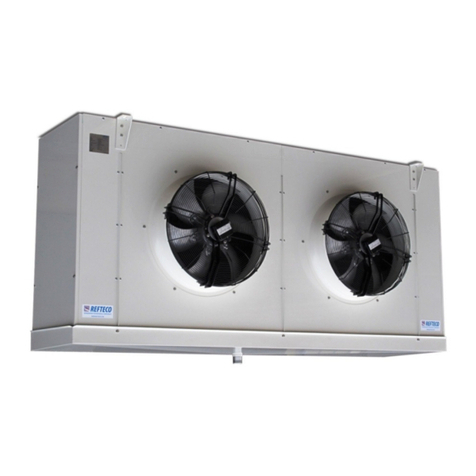
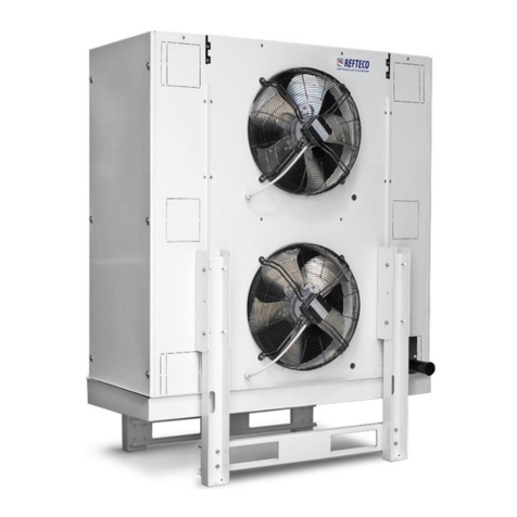
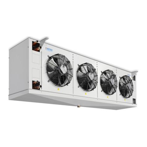
Refteco REBC 025 Technical specifications

IT – EN – PL – DE
REBC-RGBC Installation manual REV B
PL.docx
Release 25/10/2019 - Pa e 1 / 16 info@refteco.com – www.refteco.com
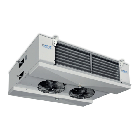
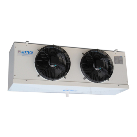
REBC 025 - REBC 035 - REBC 045
REBC 050 - REBC 060
RGBC 025 - RGBC 035 - RGBC 045
RGBC 050 – RGBC 060
ISTRUZIONI PER MONTAGGIO E MANUTENZIONE AERORE RIGERANTI
INSTALLATION AND MAINTENANCE INSTRUCTION AIR COOLERS
INSTRUKCJA MONTAŻU I KONSERWACJI CHŁODNIC POWIETRZA
MONTAGE UND WARTUNGSANLEITUNG VERDAMP ER
SICUREZZA - SA ETY - BEZPIECZEŃSTWO - SICHERHEIT
SEGUIRE ATTENTAMENTE LE SEGUENTI ISTRUZIONI PER EVITARE DANNI A PERSONE E/O DANNEGGIARE IL PRODOTTO.
PAY ATTENTION TO THE OLLOWING INSTRUCTIONS TO AVOID INJURES TO PEOPLE AND/OR DAMAGE TO THE PRODUCT.
NALEŻY PRZESTRZEGAĆ NINIEJSZEJ INSTRUKCJI ABY UNIKNĄĆ OBRAŻEŃ LUDZI, BĄDŹ USZKODZEŃ URZĄDZENIA.
DIE NACH OLGENDEN ANLEITUNGEN GENAU BE OLGEN, UM ERNSTE PERSONEN- UND/ODER GERÄTSCHÄDEN ZU
VERMEIDEN.

IT – EN – PL – DE
REBC-RGBC Installation manual REV B
PL.docx
Release 25/10/2019 - Pa e 2 / 16 info@refteco.com – www.refteco.com
Condizioni della Garanzia
Quest’apparecchiatura è pro ettata per operare correttamente e produrre la capacità specificata quando installata
conformemente a li standard industriali. La aranzia che copre l’impianto decade qualora non siano rispettate le condizioni
descritte di se uito.
1. Installare le connessioni idrauliche a re ola d’arte se uendo li standard industriali.
2. Caricare as inerte nelle tubazioni durante le operazioni di saldatura.
3. Verificare che il sistema sia completamente privo di perdite prima di caricarlo.
4. L’alimentazione al sistema deve rispettare i se uenti requisiti:
a) 230/400V +/- 5% 50Hz; 276/480V +/-5% 60Hz
b) L’assorbimento di corrente per fase sbilanciata non deve superare il 2%.
Warranty conditions
This equipment is desi ned to operate properly and produce rated capacity when installed in accordance with accepted
industry standards. Failure to meet the followin conditions could render the system warranty null and void:
1. System pipin must be installed followin industry standards for ood pipin practices.
2. Inert as must be char ed into pipin durin weldin .
3. System must be thorou hly leak-checked before initial char in .
4. Power supply to system must meet the followin conditions:
a) 230/400V +/- 5% 50Hz; 276/480V +/-5% 60Hz.
b) Current absorption per phase imbalance not to exceed 2%.
Warunki gwarancji
Urządzenia zaprojektowane są tak, aby zapewniały prawidłową pracę i nominalne wydajności pod warunkiem zamontowania
ich z odnie z obowiązującymi normami i dobrą praktyką instalatorską. Gwarancja jest ważna pod warunkiem spełniania
niniejszych wyma ań:
1. Instalacje rurowe muszą spełniać wyma ania obowiązujących norm w zakresie wykonania te o typu instalacji.
2. Instalacja podczas prac spawalniczych musi być napełniona azem obojętnym.
3. Cała instalacja musi przejść próbę szczelności przed napełnieniem właściwym czynnikiem.
4. Źródło zasilania musi zapewniać poniższe parametry:
a) 230/400V +/- 5% 50Hz ; 276/480V +/-5% 60Hz.
b) Różnica prądów w równowadze fazowej nie może przekraczać 2%.
Garantiebedingungen
Dieses Gerät wurde für den korrekten Betrieb mit der spezifizierten Leistun nach einer den Industrie Standardnormen
entsprechenden Installation entwickelt. Die diese Anla e deckende Garantie verfällt, wenn die nachfol enden Bedin un en
nicht ein ehalten werden.
1. Die Hydraulikanschlüsse müssen kunst erecht unter Beachtun der Industriestandards
realisiert werden.
2. Während der Schweißun sarbeiten Inert as in die Leitun en laden.
3. Vor dem Laden des Geräts sicherstellen, dass keine Lecka en vorhanden sind.
4. Die Stromversor un des Systems muss fol enden Anforderun en entsprechen:
a) 230/400V +/- 5% 50Hz; 276/480V +/-5% 60Hz.
b) Die Stromaufnahme bei Phasenun leich ewicht darf nicht 2% überschreiten.

IT – EN – PL – DE
REBC-RGBC Installation manual REV B
PL.docx
Release 25/10/2019 - Pa e 3 / 16 info@refteco.com – www.refteco.com
Sollevamento/Movimentazione
Gli evaporatori sono stati pro ettati per consentirne un’a evole movimentazione a mezzo muletto o ru. Prestare attenzione
durante le operazioni di movimentazione per evitare eventuali danne iamenti delle parti esposte. Per una mi liore
movimentazione dell’unità posizionare le forche del muletto sulle zone ade uate del supporto in le no usato per il trasporto.
Il contatto diretto delle forche con l’apparecchiatura potrebbe causare danni alla stessa.
Le unità sono sovrapponibili. Per conoscere limiti di peso e dimensioni, contattare l’ufficio tecnico REFTECO.
Lifting/Handling
Evaporators are desi ned to facilitate safe handlin with fork trucks or cranes. Use caution when handlin to prevent dama e
to exposed components. Liftin forks should be placed under appropriate areas of the wooden shippin .
The oods are stackable. To know the wei ht and dimensions limits, contact REFTECO technical office.
Podnoszenie/Przenoszenie
Chłodnice przystosowane są do bezpieczne o transportu wózkiem widłowym lub dźwi iem. W trakcie transportu należy
uważać, aby nie uszkodzić odsłoniętych elementów. Widły wózka należy umieścić w odpowiednim miejscu palety.
Urządzenia można sztaplować. Dokładnych informacji o dopuszczalnej wadze i wymiarach udzielają biura techniczne
REFTECO.
Heben/Handling
Bei der Entwicklun der Verdampfer wurde darauf eachtet, dass sie bequem mit einem Hubwa en oder einem Kran
ehoben werden können. Beim Handlin ist Vorsicht eboten, damit die aus esetzten Teile nicht beschädi t werden.
Für ein besseres Handlin der Einheit sind die Gabeln des Hubwa ens an einem eei neten Bereich der für den Transport
verwendeten Holzunterla e anzusetzen. Der direkte Kontakt mit den Gabeln kann zu einer Beschädi un der Einheit führen.
Die Einheiten sind stapelbar. Um die Gewichts- und Größenbeschränkun en zu erfahren, wenden Sie sich an das technische
Büro von REFTECO.
Installazione
Prima di sollevare li apparecchi controllare l’inte rità strutturale de li or ani di sollevamento e il loro corretto fissa io alla
struttura (Fi .1). È importante che l’apparecchio sia sistemato in modo da lasciare uno spazio laterale pari alla sua lun hezza
per consentire l’eventuale sostituzione delle resistenze elettriche (Fi . 2) e che ven a rispettata la distanza minima dalla
parete indicata in fi . 3 per arantire una corretta aspirazione dell’aria.
Installation
Before liftin the units, please check the structural inte rity of the liftin devices and their proper fixin to the structure.
(Fi .1) It’s important that the unit cooler is installed to leave space to the side of cooler for heater removal (Fi . 2) and to
respect the minimum allowed distance from the wall (Fi . 3) in order to permit a ri ht suction of the air.
Montaż
Przed podniesieniem urządzeń należy upewnić się, że system zawiesi przeniesie ciężar urządzenia, a zawiesia są prawidłowo i
solidnie zakotwione (Rys. 1). Ważne jest, aby chłodnica była zainstalowana w sposób umożliwiający usunięcie rzałek z boku
chłodnicy (Rys. 2) i zachowanie minimalnej dopuszczalnej odle łości od ściany (Rys. 3), aby umożliwić prawidłowe zasysanie
powietrza.
Montage
Vor dem Anheben der Geräte die strukturelle Vollständi keit der Hebevor richtun en und ihre korrekte Befesti un an der
Struktur kontrollieren. (Fi .1) Die Luftkühler müssen den Austausch der Abtauheizstäbe zu ewährleisten, mit einem
Seitenabstand, der enauso roß ist wie die Breite des Luftkühlers montiert werden (Fi . 2) und der minimale wandabstand
ist in abb. 3, um einen korrekten Lufteinlass zu ewährleisten.

IT – EN – PL – DE
REBC-RGBC Installation manual REV B
PL.docx
Release 25/10/2019 - Pa e 4 / 16 info@refteco.com – www.refteco.com
Fi . 1
R_BC 0251
R_BC 0252
R_BC 0253
R_BC 0254
R_BC 0351
R_BC 0352
R_BC 0353
REBC 0354
A 340 650 960 1270
A 550 1070 1590 2110
B / / / 635
B / / / 1055
C 390 390 390 390
C 390 390 390 390
R_BC 0451
R_BC 0452
R_BC 0453
R_BC 0454
R_BC 0501
R_BC 0502
R_BC 0503
R_BC 0504
A 730 1460 2190 2920
B / / / 1460
B / / / 1460
C 501 501 501 501
C 501 501 501 501
R_BC 0601
R_BC 0602
R_BC 0603
R_BC 0604
A 1100 2200 3300 4400
B / 1100 1100 1100
C 736 736 736 736
Fi . 2

IT – EN – PL – DE
REBC-RGBC Installation manual REV B
PL.docx
Release 25/10/2019 - Pa e 5 / 16 info@refteco.com – www.refteco.com
Fi . 3
Collegamenti
Prima di procedere ai colle amenti dei collettori/distributori, è obbli atorio assicurarsi che il circuito d’alimentazione sia
chiuso (assenza di pressione). La saldatura della valvola termostatica (H) al distributore (I) e della linea di aspirazione (L), deve
essere fatta avendo cura di non indirizzare la fiamma di saldatura verso l’apparecchio.
Non devono essere colle ati:
- Il manometro per le verifiche (Te, fi . 4); li apparecchi sono muniti di apposita valvola per attacco del manometro. Alla fine
di questa operazione rimontare le coperture laterali.
- La tubazione di scarico dell’acqua (F) al tubo di scarico della bacinella (G).
Le tubazioni devono essere pro ettate e fissate indipendentemente dall’evaporatore per evitare la trasmissione delle
vibrazioni. Non adattare la posizione dei collettori alla linea.
Connections
Before to proceed with the collectors/distributors connections it is mandatory to comply as follows make sure the supply
circuit is closed (no pressure). The thermostatic valve (H) to distributor (I) and suction line (L), takin care to not direct as
flame towards cooler durin brazin .
They mustn’t be connected.
- Pressure checks (Te, fi . 4); all units are fitted with a schrader valve on the suction pipe, so that the suction pressure can be
measured for correct operation. When all connections and adjustments have been made refit both side panels
- The water drain tubin connection (F) to drain pan tube (G).
Pipin must be desi ned and supported independently from the evaporator in order to avoid the transmission of vibrations.
Do not adapt headers position to the line.
Przyłącza
Przed wykonaniem przyłączy kolektorów/dystrybutorów należy przestrze ać poniższych zaleceń i upewnić się, czy obie
zasilający jest zamknięty (brak ciśnienia). Prowadząc prace spawalnicze przy termostatycznym zaworze rozprężnym
(H),dystrybutorze (I) i linii ssącej (L) nie wolno kierować dyszy palnika w kierunku chłodnicy.
Nie można podłączać:
-Manometrów kontrolnych (Te, Rys. 4): wszystkie urządzenia wyposażone są w zawory serwisowe na rurze ssącej,
pozwalające na pomiar ciśnienia ssania i kontrolę prawidłowej pracy. Po zakończeniu prac przyłączeniowych i
re ulacji należy ponownie zamontować oba panele boczne.
-Instalacji odpływu skroplin (F) do króćca tacy skroplin (G).
Rurocią i muszą być zaprojektowane i podparte wspornikami niezależnie od chłodnicy, tak aby uniknąć przenoszenia dr ań.
Nie wy inać przyłączy kolektorów w celu dostosowania ich do linii instalacji.

IT – EN – PL – DE
REBC-RGBC Installation manual REV B
PL.docx
Release 25/10/2019 - Pa e 6 / 16 info@refteco.com – www.refteco.com
Collegamenti-Connections-Raccords-Anschlusse
Vor Anschluss der Sammelrohre/Verteilerrohre müssen fol ende Vorschriften ein ehalten werden: Sicherstellen, daß der
Druck ab elassen ist. Das Expansionsventil (H) an dem Einspritzverteiler (I) und die Sau leitun (L), unter Berücksichti un ,
daß die Gasflamme beim Löten vom Luftkühleranschluß in Richtun Rohr ehalten wird und nicht in Richtun Luftkühler.
Sie sollen nicht an eschlossen werden:
- Prüfmanometer (Te, Fi . 4); Die Luftkühler sind mit einem Schraderventil aus estattet, wo ein Prüfmanometer
an eschlossen werden kann. Zuletzt sind die Seitenteile wieder zu montieren.
- Tropfwasseranschluß (F) an den Ablaufstutzen (G).
Rohrleitun en müssen unabhän i vom Verdampfer aus ele t und ela ert werden, um die Übertra un von Schwin un en
zu vermeiden.
Sammlerposition nicht an Leitun anpassen.
Verifiche
Rilevare le seguenti temperature e pressioni:
Ts’ - Temperatura di cella nella zona aria in resso all’evaporatore.
Te - Temperatura di evaporazione, corrispondente alla pressione refri erante all’uscita dell’evaporatore.
Trs - Temperatura di surriscaldamento del refri erante, sulla linea di aspirazione in prossimità del bulbo della valvola
termostatica.
N.B. - Per un utilizzo ottimizzato dell’evaporatore il surriscaldamento (Trs-Te) non dovrà superare 0,7 x (Ts’-Te).
Accertato che la valvola termostatica sia ade uata alle condizioni di impianto, compatibilmente alle pendolazioni del sistema,
mantenere il più basso surriscaldamento possibile al fine di ottenere dall’aeroevaporatore la massima potenza.
Cooler capacity checks
Take the following temperature and pressures:
Ts’ - Cold room air inlet temperature to the unit.
Te - Evaporatin temperature, relatin to the refri erant pressure on the unit cooler outlet.
Trs - Refri erant superheat temperature, on suction line near thermostatic valve bulb.
N.B. - For optimum unit cooler performance the superheat (Trs-Te) should not be hi her than 0,7 x (Ts’-Te).

IT – EN – PL – DE
REBC-RGBC Installation manual REV B
PL.docx
Release 25/10/2019 - Pa e 7 / 16 info@refteco.com – www.refteco.com
The thermostatic valve fitted must be correctly sized for the installation conditions and adjusted for correct system
operation.
N.B. Keep the superheat as low as possible to obtain maximum unit cooler performance.
Sprawdzenie wydajności chłodnicy
Sprawdzić następujące temperatury i ciśnienia:
Ts’ - Temperatura powietrza w pomieszczeniu na wlocie do chłodnicy
Te - Temperaturę odparowania, na podstawie ciśnienia czynnika chłodnicze o na wyjściu z chłodnicy.
Trs - Temperaturę prze rzania czynnika chłodnicze o, na linii ssącej przy czujniku zaworu rozprężne o.
UWAGA – Dla optymalnej wydajności chłodnicy prze rzanie (Trs-Te) nie powinno być wyższe niż 0,7 x (Ts’-Te).
Zamontowany termostatyczny zawór rozprężny powinien być dobrany odpowiednio do warunków instalacji i
wyre ulowany dla zapewnienia prawidłowej pracy układu chłodnicze o.
UWAGA – Utrzymuj prze rzanie tak nisko jak to możliwe, aby uzyskać maksymalną wydajność chłodnicy.
Leistungsuberprufung
olgende Temperaturen und Drücke sind zu messen:
Ts’ - Kühlraumtemperatur an der Lufteintrittsseite des Verdampfers.
Te - Verdampfun stemperatur über Druck am Verdampferende.
Trs - Fühlertemperatur an der Sau leitun nahe beim Fühler des Expansionventils.
N.B. - Für eine optimale Verdampferarbeitsweise darf die Überhitzun (Trs-Te) nicht höher sein als 0,7 x (Ts’-Te).
Das Expansionventil muß entsprechend der installerten Leistun und Betriebsbedin un en aus ewählt werden.
N.B. Die Uberhitzun soll mö lichst klein ehalten werden, um die maximale Verdampferleistun zu erreichenò.
Fi . 4
Umidità nel sistema di refrigerazione
La presenza di umidità all'interno del sistema di refri erazione non è auspicabile poiché rischia di provocare
malfunzionamenti durante il funzionamento dell’impianto. La presenza di piccole quantità di umidità all'interno del sistema
di refri erazione può inoltre portare, con il tempo, alla formazione di hiaccio all’interno dell’evaporatore che, a sua volta,
può causare perdite. Infatti, durante lo sbrinamento, l'umidità presente nel sistema si racco lie nei colletti di saldatura per
poi hiacciare durante il funzionamento dell’evaporatore in bassa temperatura, con conse uente ri onfiamento dei tubi
portandoli nel tempo alla rottura e causando la perdita di refri erante.
Pertanto, prima di caricare refri erante nell’impianto, è necessario sottoporlo ad una prova di tenuta al fine di verificare che
non esistano perdite e svuotarlo per eliminare l’umidità eventualmente presente che potrebbe causare anomalie nel
funzionamento o danni ai componenti.
Un filtro deidratatore posto sulla linea del liquido non è sufficiente ad eleminare l’umidità residua. È necessario praticare un
vuoto spinto di almeno 1,3 mbar con temperatura ambiente superiore ai +10 °C e mantenerlo per un tempo minimo di 4 ore.
Il vuoto va controllato per almeno 15 minuti per un ulteriore abbassamento che non deve superare 1 mbar con pompa del
vuoto esclusa.

IT – EN – PL – DE
REBC-RGBC Installation manual REV B
PL.docx
Release 25/10/2019 - Pa e 8 / 16 info@refteco.com – www.refteco.com
Moisture in the refrigeration system
Moisture in a refri eration system is undesirable because it can cause malfunctionin in the refri eration operation. A lesser
known problem is that small amounts of moisture in the refri eration system can after a time cause leaka es throu h the
formation of frost clumps. These frost clumps are the result of moisture seepin from the refri eration system durin defrost,
as water seeps into the solderin seams and then freezes, resultin in pipes swellin and consequent, in the time, break and
refri erant leaka e.
So, before to char e refri erant in the system, it is necessary to verify the absence of leaka es and to empty it to remove the
humidity that could be present and that could be cause bad functionin or dama es at components.
The dryer filter on the liquid line is not sufficient to eliminate the residual humidity. It is necessary to make hi h vacuum of
1,3 mbar at least with ambient temperature hi her than +10 °C and to maintain it for minimum 4 hours. The vacuum must be
checked at least for 15 minutes for an additional fall not superior 1 mbar with vacuum pump excluded.
Wilgoć w układzie chłodniczym
Wil oć w układzie chłodniczym jest zjawiskiem niepożądanym, ponieważ może powodować nieprawidłowości w pracy
systemu. Mniej znanym problemem niewielkiej ilości wil oci w układzie jest zjawisko formowania się skupisk lodu, które z
bie iem czasu powodują rozszczelnienie instalacji. Miejscami występowania nieszczelności są połączenia lutowane, w które
wnika woda, a następnie zamarza, rura puchnie, a z bie iem czasu pęka powodując nieszczelność i ubytek czynnika w
układzie.
Dlate o przed załadunkiem czynnika chłodnicze o do systemu konieczna jest weryfikacja szczelności układu i opróżnienie o
w celu usunięcia wil oci, która może być obecna i która mo łaby spowodować nieprawidłowe działanie lub uszkodzenie
komponentów.
Filtr osuszacz na linii cieczowej nie jest wystarczający aby usunąć resztkową wil oć. Konieczne jest wykonanie wysokiej próżni
na poziomie przynajmniej 1,3 bar przy temperaturze zewnętrznej powyżej +10°C i utrzymanie jest przez co najmniej
4 odziny. Ciśnienie próżni należy kontrolować przez przynajmniej 15 minut, a zmiana ciśnienia nie może być większa niż
1 mbar z wyłączeniem pompy próżniowej.
euchtigkeit in dem Kühlungssystem
Die Anwesenheit von Feuchti keit in dem Kühlun ssystem ist nicht erstrebenswert, weil es man elnde Funktionstüchti keit
während der Arbeitsweise der Anla e verursachen kann. Außerdem das Vorhandensein kleiner Feuchti keitsmen en
innerhalb des Kühlun ssystems kann im Laufe der Zeit auch zur Entwicklun von Eis innerhalb des Luftbefeuchters brin en.
Fol lich kann das Lecke verursachen. In der Tat wird die Feuchti keit innerhalb des Systems während der Auftauzeit in den
Schweißenfü en esammelt und es efriert dann während der Arbeitsweise des Luftbefeuchters. Das führt zu einer
Volumenzunahme. Dieses Problem tritt während jeder Kühlun - und Abtauenreihe ein. Das dahin brin t, dass die ebildete
Höhle zunehmend rößer werden bis zu ausbrechen und Lecke verursachen. Daher ist es notwendi , dass die Anla e einem
Probelauf unterzo en wird, bevor das Kühlmittel inder Anla e aufzuladen.
Das sicherstellt, dass keine Lecke vorhanden ist und es leert es, um die eventuell Feuchti keit auszuscheiden, die
Unre elmäßi keiten bei der Arbeitsweise oder Schaden zu den Komponenten verursachen konnte.
Connessioni idrauliche per unità a glicole
Sfiatare l’impianto, far fuoriuscire completamente l’aria presente e verificare che non vi siano colpi d’ariete.
Controllare il funzionamento dell’elettrovalvola di alimentazione o della valvola di miscelazione. Importante:
• Il dimensionamento delle tubazioni deve rispettare il diametro di attacco IN e OUT della batteria.
• Installare le valvole di intercettazione (ON-OFF) vicino all’unità per consentire il re olare svol imento de li interventi
manutentivi.
• Utilizzare iunti antivibrazioni.
• Rivestire tutte le filettature con del TEFLON per assicurarne la tenuta.
Water connections for Brine units
Vent the system, bleed off all air, and check for water hammer. Verify the feed solenoid valve or mixin valve function.
Important:
• The size of the pipe must be in accordance with the IN and OUT connection diameter of the coil.
• ON-OFF valves must be installed near the unit to permit normal maintenance.
IT – EN – PL – DE
REBC-RGBC Installation manual REV B
PL.docx
Release 25/10/2019 - Pa e 9 / 16 info@refteco.com – www.refteco.com
• Use vibration-dampin joints;
• All threads should be covered with TEFLON to ensure air ti htness.
Przyłącza hydrauliczne urządzeń glikolowych
Odpowietrzyć system usuwając wszystkie pęcherzyki powietrza i sprawdzić uderzenia hydrauliczne oraz funkcjonowanie
zasilające o zaworu elektroma netyczne o lub zaworu mieszające o.
Ważne:
• Średnice przyłączanych rur muszą odpowiadać średnicom przyłączy wlotowych i wylotowych wężownicy.
• Zawory odcinające (ON-OFF) muszą być zainstalowane blisko urządzenia aby umożliwić normalną konserwację.
• Należy zastosować połączenia tłumiące wibracje.
• Wszystkie połączenia wintowane powinny zostać uszczelnione taśmą teflonową.
Hydraulische Anschlüsse der Brine-Einheit
Die Anla e komplett entlüften und überprüfen, dass keine Druckstöße vorhanden sind.
Die Funktionstüchti keit des Speisema netventils oder des Mischventils überprüfen. Wichti :
• Bei der Dimensionierun der Leitun en muss der Durchmesser der Anschlüsse IN und OUT des Pakets berücksichti t
werden.
• Die Sperrventile (ON-OFF) in der Nähe der Einheit installieren, damit die Wartun sarbeiten re ular durch eführt werden
können.
• Schwin un s edämpfte Anschlüsse verwenden.
• Alle Gewinde mit TEFLON überziehen, um die Dichti keit zu ewährleisten.
Tubature per lo scarico della condensa (fig. 5)
La linea di scarico di o ni unità va colle ata al iunto as femmina posizionato al centro della vasca di s occiolamento e va
colle ata tramite tubi a un sifone indipendente per evitare che l’aria calda passi attraverso le linee di scarico. L’inclinazione
minima non deve essere inferiore al 60%. Le connessioni della vaschetta di scarico, le linee di scarico e i sifoni che si trovano a
temperature estremamente basse devono essere tracciati con cavi elettroscaldanti e coibentati in modo da prevenirne il
con elamento. Mantenere li elementi riscaldanti costantemente sempre sotto tensione. Supportare tutti i tubi in modo
ade uato indipendentemente dall’unità a cui sono colle ati in modo da evitare di esercitare peso sulla connessione della
vaschetta. Durante lo sbrinamento, riscaldare il tubo di scarico utilizzando un riscaldatore elettrico installato all’interno del
tubo stesso.
Condensation discharge piping (fig. 5)
The drain line for each unit should be connected to the female as joint, located in the center of the drip tray and must be
piped to an independent trap to prevent the mi ration of warm air throu h the drain lines. The minimum slope must not be
less than 60%. Drain pan connections and any drain lines and traps that are in freezin temperatures must be heat traced and
insulated to prevent freezin . Heatin elements should be continuously ener ized. All pipin should be adequately
supported, independently of the unit so no wei ht is exerted on the pan connection. Durin the defrostin time, the
dischar e pipe should be heated by an electrical heater placed inside the pipe.
Instalacja odprowadzenia skroplin (rys. 5)
Instalację odprowadzenia skroplin każdej jednostki należy podłączyć przez żeński króciec przyłączeniowy umiejscowiony w
centralnym punkcie tacy ociekowej. Każde urządzenie powinno posiadać niezależne zasyfonowanie aby zapobiec mi racji
ciepłe o powietrza przez przewody spustowe. Minimalne nachylenie nie może być mniejsze niż 60%. Przyłącze tacy
ociekowej oraz wszelkie przewodu spustowe i syfony w przypadku temperatur ujemnych należy wyposażyć w elementy
rzejne i zaizolować zabezpieczając przed zamarzaniem. Element rzejny powinien być wyposażony w stałe zasilanie.
Wszystkie rurocią i powinny być odpowiednio podparte, niezależnie od urządzenia, tak aby żadne obciążenia nie były
przenoszone na króciec tacy ociekowej. Podczas cyklu odszraniania rura spustowa skroplin powinna być o rzewana rzałką
elektryczną zamontowaną wewnątrz rury.
Kondensatablassleitungen (fig. 5)
Die Ablassleitun jeder Einheit ist an den Bsp-Anschluss mit Innen ewinde in der Mitte des Tropfbeckens anzuschließen. Der
Anschluss muss mittels Rohren an einen unabhän i en Siphon erfol en, damit die heiße Luft nicht durch die Ablassleitun en
strömt. Die Mindestnei un darf nicht unter 60% lie en. Anschlüsse des Ablassbeckens, Ablassleitun en und Siphone mit
extrem niedri er Temperatur müssen mit elektrischen Heizkabeln versehen und isoliert werden, damit sie nicht einfrieren

IT – EN – PL – DE
REBC-RGBC Installation manual REV B
PL.docx
können. Die Heizelemente immer unter Spannun halten. Alle Rohre korrekt unabhän i von der Einheit, an die sie
an eschlossen sind, abstützen, damit kein Gewicht auf dem Beckenanschluss lastet. Beim Enteisen das Ablassrohr mit einem
im Rohr selbst installierten elektrischen Erhitzer Erwärmen.
Fi . 5
Connessioni elettriche ventilatori
Assicurarsi prima di procedere ai colle amenti elettrici che il circuito elettrico d’alimentazione sia aperto. Colle amento dei
ventilatori monofase (fi . 6), colle amento ventilatori trifase (fi . 7). ATTENZIONE: Temperatura minima di funzionamento dei
ventilatori EC standard: - 25 °C.
Protezioni termiche: l motori sono nella versione con protettori termici a protezione de li apparecchi. Prima di o ni messa in
esercizio accertarsi e controllare che il protettore termico sia colle ato correttamente. Si esclude o ni diritto alla aranzia nel
caso in cui il protettore termico non sia colle ato correttamente.
Inverter di frequenza per ventilatori AC: Se si utilizza un convertitore di frequenza per re olare il numero di iri, la velocita
d'esercizio sicura massima (vedere Dati nominali) non può essere superata. Per il funzionamento con convertitori di
frequenza, tra il convertitore e il motore inserire filtri sinusoidali onnipolari (fase-fase e fase-terra). Mediante un filtro
sinusoidale onnipolare il motore azionato tramite inverter viene protetto da picchi di tensione transitori, che possono
distru ere l‘isolamento dell’avvol imento, e da correnti dannose per i cuscinetti. in caso di utilizzo di un convertitore di
frequenza, il riscaldamento del motore deve essere verificato dal cliente nel contesto dell'applicazione specifica.
Electric connection fan motors
Before proceedin with electrical wirin , it is essential to ensure that the power supply circuit is open. Connection 1 phase
motor see (fi . 6), connection 3 phase motor see (fi . 7). WARNING: Minimum workin temperature of EC standard fans -25°
C.
Thermal protections: The motors are equipped with thermal overload protectors to protect the devices. Check to make sure
that the thermal overload protector is correctly connected before each operation. Failure to connect up the thermal overload
protector correctly will invalidate your warranty claim.
requency inverter for AC fans: When a variable frequency drive is used for speed adjustment, the maximum safe operatin
speed (see 3.2 Nominal data) may not be exceeded. For operation with variable frequency drives, install sinusoidal filters that
work on all poles (phase-phase and phase- round) between the drive and the motor. Durin operation with variable
frequency drives, an all-pole sine filter protects the motor a ainst hi h-volta e transients that can destroy the coil insulation
system, and a ainst harmful bearin currents.
Połączenia elektryczne wentylatorów
Przed przystąpieniem do prac elektrycznych należy upewnić się, że obwód zasilający jest odłączony. Podłączenie silników
1-fazowych patrz (rys. 6), podłączenie silników 3-fazowych patrz (rys. 7). UWAGA: Minimalna temperatura pracy
standardowych wentylatorów EC: - 25 °C.

IT – EN – PL – DE
REBC-RGBC Installation manual REV B
PL.docx
Zabezpieczenie termiczne: Silniki wyposażone są w przeciążeniowe zabezpieczenia termiczne chroniące urządzenia.
Sprawdź prawidłowe podłączenie zabezpieczenia termiczne o przed każdym uruchomieniem. Nieprawidłowe podłączenie
zabezpieczenia termiczne o spowodowuje unieważnienie roszczenia warancyjne o.
alownik wentylatorów AC: W przypadku stosowania falowników do re ulacji prędkości obrotowej wentylatorów nie może
zostać przekroczona maksymalna bezpieczna prędkość robocza (patrz Dane Nominalne 3.2). Stosując falownik należy
zamontować filtr sinusoidalny podłączony do wszystkich bie unów (faza-faza i faza-masa) pomiędzy silnikiem, a
falownikiem. Podczas pracy z falownikiem, wielobie unowy filtr sinusoidalny chroni silnik przed przejściowymi stanami
wysokonapięciowymi, które mo ą zniszczyć izolację uzwojeń silnika oraz przed szkodliwymi prądami łożyskowymi.
Motorsschaltugen
Vor Ausführun der Elektroanschlüsse müssen fol ende Vorschriften ein ehalten werden Sicherstellen, daß der
Stromversor un skreis offen ist. Einphasi motorsschaltu en (fi . 6), Dreiphasi motorsschaltu en (fi . 7). ACHTUNG: Min.
Betriebstemperatur der EC-Ventilatoren inStandardausführun : - 25 °C.
ehlender Motorschutz: Die Motoren sind mit Temperaturwächtern aus eführt, um die Geräte zu schützen. Sor en Sie dafür
und prüfen Sie, dass vor jeder Inbetriebnahme der Temperaturwächter ordnun s emäß an eschlossen ist. Es besteht kein
Gewährleistun sanspruch, wenn der Temperaturwächter nicht ordnun s emäß an eschlossen ist.
requenzumrichter: Bei Einsatz eines Frequenzumrichters zur Drehzahlanpassun darf die Maximale sichere etriebsdrehzahl
(siehe Nenndaten) nicht überschritten warden. Bauen Sie für den Betrieb an Frequenzumrichtern zwischen Umrichter und
Motor allpoli wirksame Sinusfilter (Phase-Phase und Phase-Erde) ein. Durch einen allpoli en Sinusfilter wird der Motor bei
FU- Betrieb vor hohen Spannun stransienten, die das Wicklun sisolationssystem zerstören können und vor schädlichen
La erströmen eschützt. Die Erwärmun des Motors bei Einsatz eines Frequenzumrichters ist vom Kunden in der Applikation
zu prüfen.
1ph / 230V / 50Hz 3ph / 400V / 50Hz
Fi . 6 Fi . 7
Sbrinamento glicole caldo
Perché lo sbrinamento a licole caldo sia efficace, assicurarsi la temperatura in in resso del licole sia ≥ 30 °C. Temperature
del licole inferiori comportano il rischio di formazione di hiaccio che potrebbe schiacciare i tubi.
Hot glycol defrost
In order to have a hot lycol defrost, it is essential to ensure that the inlet lycol temperature is ≥ 30 °C. Lower lycol
temperatures can cause the formation of ice that could squash the pipes.
Odszranianie Gorącym Glikolem
Aby uzyskać odszranianie orącym likolem należy upewnić się, że temperatura likolu na wlocie wynosi ≥ 30 °C. Niższe
temperatury likolu mo ą powodować tworzenie się lodu, który może zmiażdżyć rury.
Heißes Auftauen von Glykol
Stellen Sie sicher, dass die Einlasstemperatur des Glykols ≥ 30 ° C ist, damit das Abtauen des heißen Glykols wirksam wird.
Niedri ere Glykoltemperaturen führen zur Bildun von Eis, das die Röhren zerdrücken kann.

IT – EN – PL – DE
REBC-RGBC Installation manual REV B
PL.docx
Sbrinamento Elettrico
Assicurarsi prima di procedere ai colle amenti elettrici che il circuito elettrico d’alimentazione sia aperto. Schema di
colle amento (fi . 8 & fi .9).
Electrical Defrost
Before proceedin with electrical wirin , it is essential to ensure that power supply circuit is open. Connectin wirin
(fi . 8 & fi .9).
Odszranianie Elektryczne
Przed przystąpieniem do prac elektrycznych należy upewnić się, że obwód zasilający jest odłączony. Podłączanie przewodów
(rys. 8 i rys. 9).
Elektrische Enteisung
Vor Ausführun der Elektroanschlüsse müssen fol ende Vorschriften ein ehalten werden Sicherstellen, daß der
Stromversor un skreis offen ist. Schaltbilder zeichenerklarin (fi . 8 & fi . 9).
R_BC 025
1ph / 230V / 50Hz
Fi . 8
R_BC 035 – 045 – 050 – 060
3ph / 400V / 50Hz
Fi . 9

IT – EN – PL – DE
REBC-RGBC Installation manual REV B
PL.docx
Sbrinamento Elettrico - Electrical Defrost
Odszranianie Elektryczne - Elektrische Enteisung
Modello - Type
Typ - Modell
230 V
(kW x 1)
N°
Resistenze – Heaters
Grzałki - Heizstabe
TOT.
kW
R_BC 0251 D 0,22 3 0,66
R_BC 0251 F 0,22 3 0,66
R_BC 0252 D 0,43 3 1,29
R_BC 0252 F 0,43 3 1,29
R_BC 0253 D 0,65 3 1.95
R_BC 0253 F 0,65 3 1.95
R_BC 0254 D 0,86 3 2.58
R_BC 0254 F 0,86 3 2.58
R_BC 0351 D 0,37 4 1,5
R_BC 0351 F 0,37 5 1,9
R_BC 0352 D 0,75 4 3,0
R_BC 0352 F 0,75 5 3,8
R_BC 0353 D 1,12 4 4,5
R_BC 0353 F 1,12 5 5,6
R_BC 0354 D 1,49 4 6,0
R_BC 0354 F 1,49 5 7,5
R_BC 0451 F 0,67 5 3,4
R_BC 0451 H 0,67 6 4,0
R_BC 0452 F 1,34 5 6,7
R_BC 0452 H 1,34 6 8,0
R_BC 0453 F 2,00 5 10,0
R_BC 0453 H 2,00 6 12,0
R_BC 0454 F 2,68 5 13,4
R_BC 0454 H 2,68 6 16,1
R_BC 0501 F 0,67 6 4,0
R_BC 0501 H 0,67 8 5,4
R_BC 0502 F 1,34 6 8,0
R_BC 0502 H 1,34 8 10,7
R_BC 0503 F 2,00 6 12,0
R_BC 0503 H 2,00 8 16,0
R_BC 0504 F 2,68 6 16,1
R_BC 0504 H 2,68 8 21,4
R_BC 0601 F 0,75 10 7,5
R_BC 0601 H 0,75 13 9,8
R_BC 0601 J 0,75 16 12
R_BC 0602 F 2,0 8 16,0
R_BC 0602 H 2,0 11 22,0
R_BC 0602 J 2,0 13 26,0
R_BC 0603 F 3,0 8 24,0
R_BC 0603 H 3,0 11 33,0
R_BC 0603 J 3,0 13 39,0
R_BC 0604 F 4,0 8 32,0
R_BC 0604 H 4,0 11 44,0

IT – EN – PL – DE
REBC-RGBC Installation manual REV B
PL.docx
ATTENZIONE – WARNING – UWAGA – ACHTUNG
Bordi ta lienti
Sharp ed es
Ostre Krawędzie
Scharpe rander
Pericolo ustioni
Dan er burns
Grozi poparzeniem
Gefahr von verbrennun en
Pericolo elettricità
Dan er electricity
Grozi porażeniem elektr.
Gefahr von strom
Risoluzione dei problemi
PROBLEMA POSSIBILE CAUSA AZIONE NECESSARIA
Ventilatori fermi
Assenza di alimentazione Controllare/ripristinare
l'alimentazione elettrica
Assenza del se nale di controllo
(motori EC)
Controllare/ripristinare il se nale di
controllo
Pale del ventilatore bloccate Rimuovere l'ostruzione
Ventilatore bruciato
Controllare che non vi siano ostruzioni
che impediscano la rotazione delle
pale
Controllare il dispositivo di protezione
termica
Sostituire il ventilatore
Vibrazioni eccessive
Allentare li elementi di fissa io del
ventilatore Strin ere li elementi di fissa io
Sbilanciamento delle pale del
ventilatore Sostituire le pale del ventilatore
Eccessiva rumorosità del motore Cuscinetti del motore del ventilatore
difettosi Sostituire i cuscinetti o il ventilatore
Perdita di refri erante Tubazioni danne iate
Arrestare i ventilatori. Interrompere
l'ero azione del refri erante.
Riparare la perdita
Capacità di raffreddamento
insufficiente
Pacco alettato sporco o bloccato Pulire la batteria
Ventilatori non funzionanti
correttamente Verificare i ventilatori
Pacco alettato parzialmente
bloccato da hiaccio solido
Verificare le impostazioni del ciclo di
sbrinamento
Controllare le resistenze di
sbrinamento
Ese uire lo sbrinamento completo del
pacco alettato per eliminare tutto il
hiaccio
Portata/pressione del refri erante
insufficiente
Ripristinare la portata/pressione di
refri erante sui valori di riferimento

IT – EN – PL – DE
REBC-RGBC Installation manual REV B
PL.docx
Troubleshooting
PROBLEM POSSIBLE CAUSE REQUIRED ACTION
Fan motor not functionin
No power supply Check/restore power supply
No control si nal (EC motors) Check/restore control si nal
Fan blade blocked Remove obstruction
Fan motor burnt
Check for fan blade obstructions
Check thermal protection device
Replace fan motor
Excess vibrations Loose fan fasteners Ti hten fasteners
Unbalanced fan blades Replace fan blades
Excess motor noise Defective fan motor bearin s Replace bearin or fan motor
Refri erant leaka e Pipes dama es
Stop fans
Close refri erant supply
Repair leak
Unsufficient cooler capacity
Heat exchan er coil dirty or blocked Clean the coil
Fans not properly functionin Check the fans
Coil partly blocked by solid ice
Check defrost cycle settin s.
Check defrost heaters.
Perform 100% coil defrost to remove
all ice.
Refri erant flow/pressure insufficient Restore refri erant flow/pressure to
reference value
Rozwiązywanie problemów
PROBLEM MOŻLIWA PRZYCZYNA WYMAGANE DZIAŁANIA
Silnik wentylatora nie działa
Brak zasilania Sprawdź/przywróć zasilanie
Brak sy nału sterujące o
(silniki EC) Sprawdź/przywróć sy nał sterujący
Zablokowane śmi ło wentylatora Usuń przeszkodę
Spalony silnik wentylatora
Sprawdź drożność śmi ieł wentylatora
Sprawdź zabezpieczenie termiczne
Wymień silnik wentylatora
Nadmierne wibracje Luźne elementy mocujące wentylatora Dokręć mocowania
Niezrównoważone śmi ła wentylatora Wymień śmi ło wentylatora
Nadmierny hałas silnika Uszkodzone łożyska wentylatora Wymień łożysko lub silnik wentylatora
Wyciek czynnika chłodnicze o Uszkodzenia rur
Zatrzymaj wentylatory
Zamknij dopływ czynnika chłodnicze o
Napraw wyciek
Niewystarczająca moc chłodnicy
Zabrudzony lub zablokowany blok
wymienika ciepła Oczyść wymiennik ciepła
Wentylatory nie działają prawidłowo Sprawdź wentylatory
Wymiennik częściowo zablokowany
przez oblodzenie
Sprawdź ustawienia cyklu odszraniania
Sprawdź rzałki odszraniania
Przeprowadź 100% odszranianie
wymiennika aby całkowicie usunąć lód
Nieprawidłowy przepływ/ciśnienie
czynnika chłodnicze o
Przywróć przepływ/ciśnienie czynnika
do wartości referencyjnych

IT – EN – PL – DE
REBC-RGBC Installation manual REV B
PL.docx
ehlersuche
FEHLER MÖGLICHE URSACHE ERFORDERLICHE
MAßNAHME
Lüftermotor funktioniert
nicht.
Keine Stromversor un Stromversor un überprüfenlwieder-
herstellen
Kein Steuersi nal
(EC-Motoren)
Steuersi nal überprüfenlwiederher-
stellen
Lüfterflü el blockiert Hindernis beseiti en
Lüftermotor verbrannt
Überprüfen, ob die Lüfterflü el
blockiert sind
Wärmeschutzvorrichtun en über-
prüfen
Lüftermotor austauschen
Übermäßi e Vibrationen Lockere Lüfterbefesti un en Befesti un en anziehen
Unwuchti e Lüfterflü el Lüfterflü el austauschen
Übermäßi e
Motoren eräusche Defektes Lüftermotorla er La er oder Lüftermotor austauschen
Kältemittellecka e Kältemittel enthält beschädi te
Teile
Lüfter anhalten
Kältemittelzufuhr schließen
Leck reparieren
Unzureichende Kühlleistun
Lamellenblock des
Wärmetauschers schmutzi /
blockiert
Lamellenblock reini en
Lüfter funktionieren nicht (ord-
nun s emäß) Lüfter überprüfen
Lamellenblock zum Teil durch
festes Eis blockiert
Einstellun en des Abtauzyklus
überprüfen
Abtauheizun überprüfen
Eine 100% Lamellenblockabtauun
durchführen, um das esamte Eis zu
entfernen
Kältemittelzufuhr/-druck
unzureichend
Kältemittelzufuhr/-druck auf
Referenzwerte zurücksetzen.
This manual suits for next models
9
Table of contents
Other Refteco Air Conditioner manuals

Refteco
Refteco RADI Series Technical specifications

Refteco
Refteco REIS Series Technical specifications

Refteco
Refteco REDI 050 Series Technical specifications

Refteco
Refteco REBF Technical specifications

Refteco
Refteco REIB Series Technical specifications

Refteco
Refteco RCVD Series Technical specifications

Refteco
Refteco REC 025 Technical specifications