1
F O R M
Evergreen®VS User Interface
Evergreen VS Motor
Installation Guide
G0075E
Revised
January 2020
Regal Beloit America, Inc.
1325 Heil Quaker Blvd.
LaVergne, TN 37086
Customer Service: 800 672 6495
thedealertoolbox.com
www.regalbeloit.com
CAUTION indicates a hazardous situation that, if not avoided,
could result in minor or moderate injury.
• Periodic inspections should be performed. Failure to perform
proper maintenance could result in premature product failure, in
addition to minor or moderate injury.
• Installation and service of this Evergreen VS user interface and
motor should be performed only by trained service technicians
familiar with these products.
• This Evergreen VS user interface and motor should be
installed in accordance with accepted practices and installation
instructions, and in compliance with all national and local codes.
WARNING indicates a hazardous situation that, if not avoided, could
result in death or serious injury.
• Read and follow all instructions carefully.
• Disconnect and lock out the main power from the unit being
serviced before installing the Evergreen VS user interface and
motor. It is also a good practice to confirm that the power is
disconnected with a voltmeter.
• Do not operate equipment without guards in place.
• Improper installation, adjustment, alteration, service,
maintenance, or use could cause explosion, fire, electrical shock,
or other conditions. Consult a qualified installer, service agency,
or your distributor or branch for information or assistance.
The qualified installer or agency must use the supplied or
recommended parts when installing or servicing this product.
• After installing the Evergreen VS user interface and motor, it is
the responsibility of the installing technician to verify the HVAC
system matches the manufacturer’s requirements for proper
operation, capacity, efficiency and safety. This includes but is not
limited to measuring the airflow and adjusting the Evergreen
VS user interface airflow and delay setting in each mode of
operation.
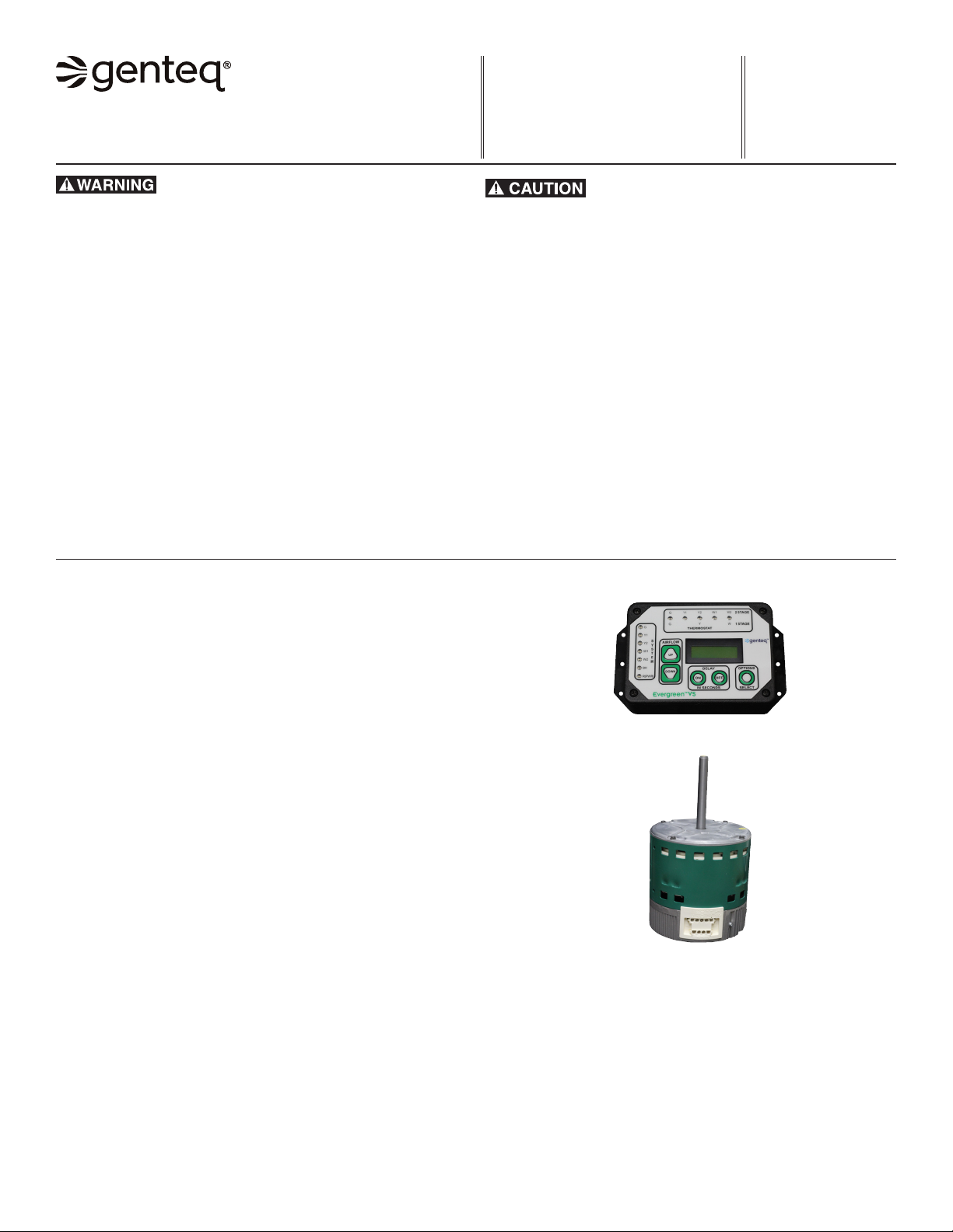
Evergreen®VS Motor
Table of Contents
1. Introduction
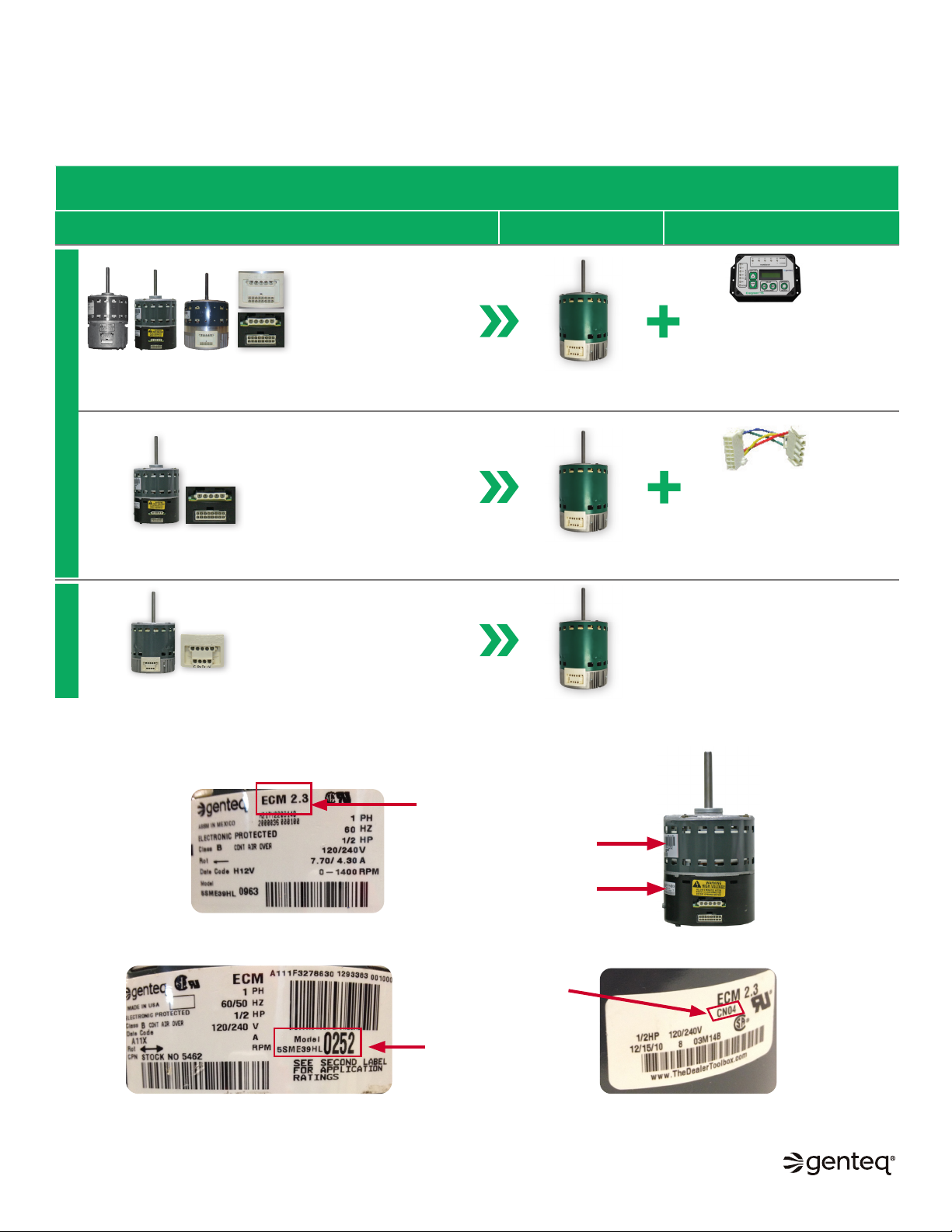
2. Evergreen VS Product Line Applications
and How to ID Genteq ECM Motors
3. Model 2.0, Genteq Models 2.3 and Eon®Applications
and Removal and Installation of the Motor
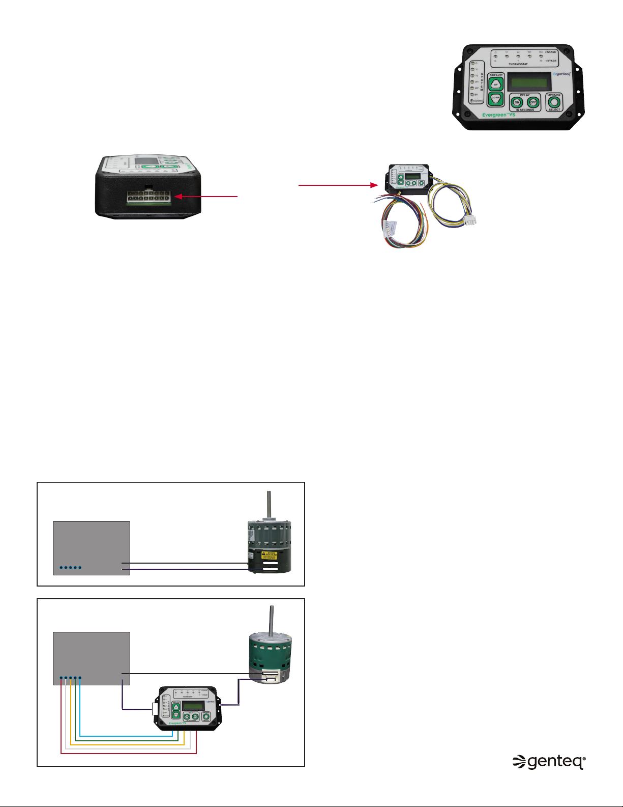
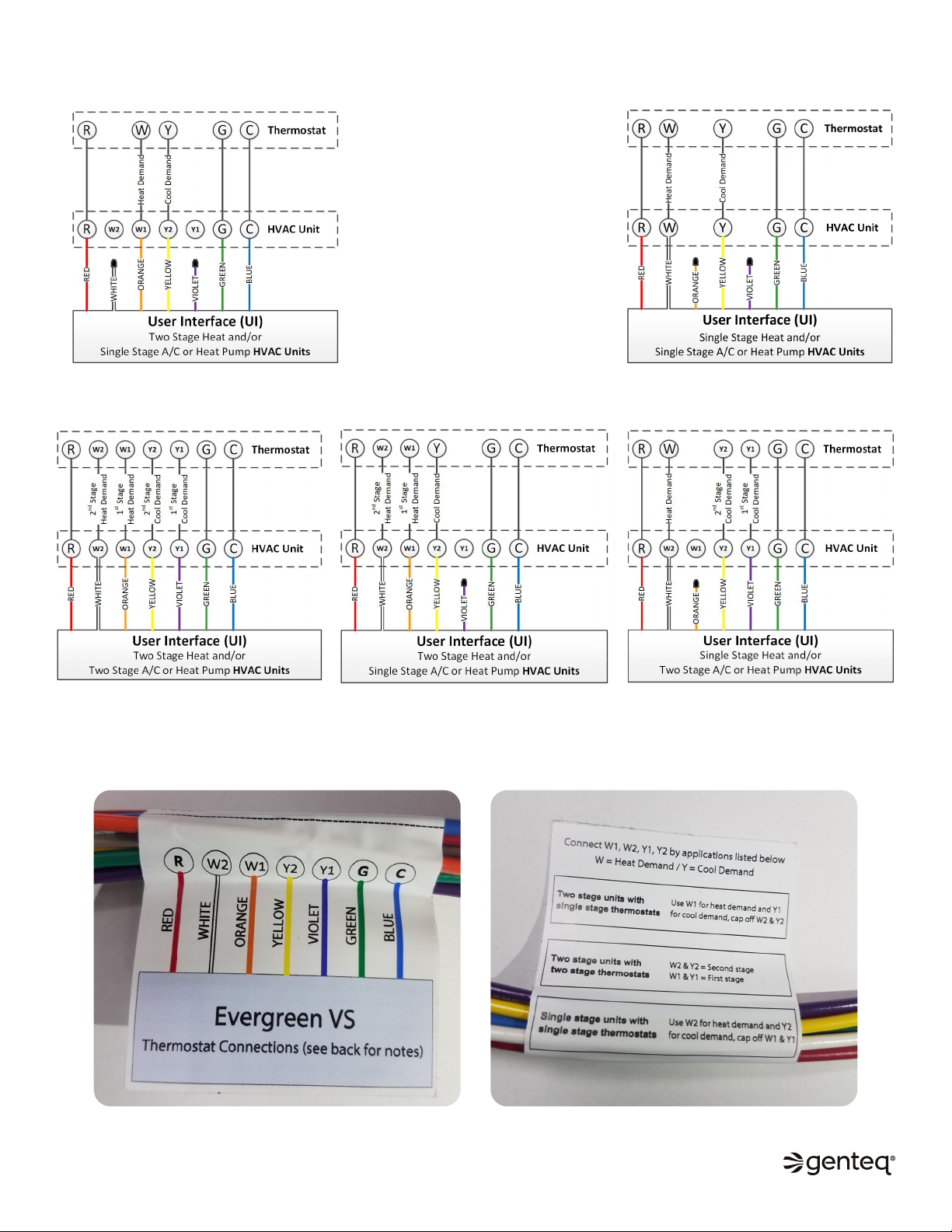
4-5. Installation of the Evergreen VS User Interface (UI)
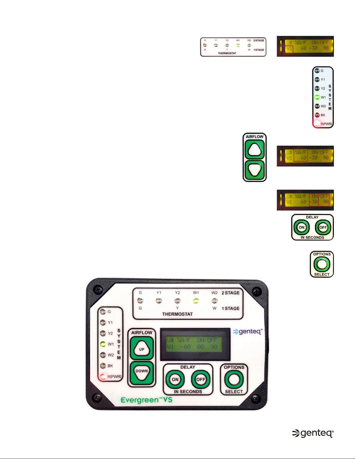
6. Evergreen VS User Interface (UI) Overview
7. Sequence of Operation
8. Commissioning
9. Airflow and Delay Adjustments
10-11. Options Menu
12. Evergreen VS User Interface (UI) Specifications
and Evergreen VS Motor Specifications
and Technical Support and Warranty
Page
Evergreen®VS User Interface
©2019, 2020 Regal Beloit Corporation, All Rights Reserved. MCIM20008E • Form# G0075E
INTRODUCTION
The Evergreen VS motor is designed to replace Genteq constant airflow (variable speed) ECM motors. This includes ECM indoor
blower motors made by Regal and its predecessor manufacturer and sold under other Regal and predecessor manufacturer brands.
The Evergreen VS motor is a constant airflow (variable speed) motor. It will operate in constant airflow mode when it is receiving digital
serial interface (DSI) and constant torque mode when it is receiving pulse width modulation (PWM) communication.