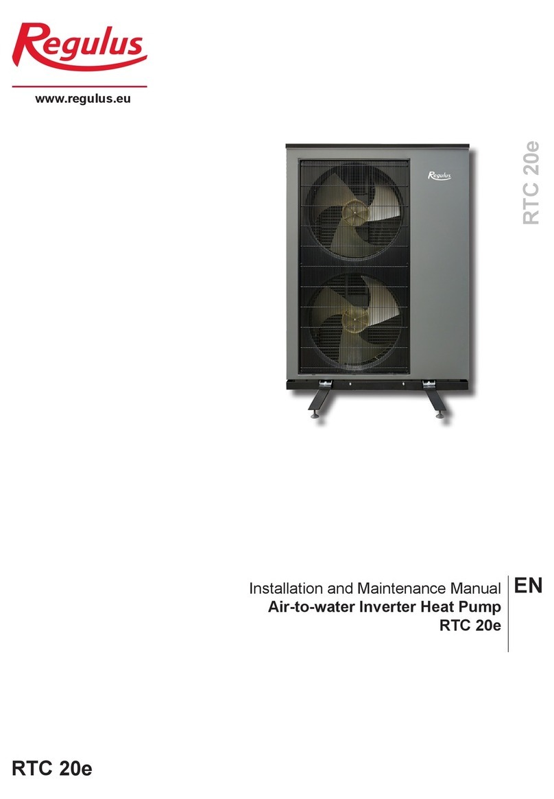
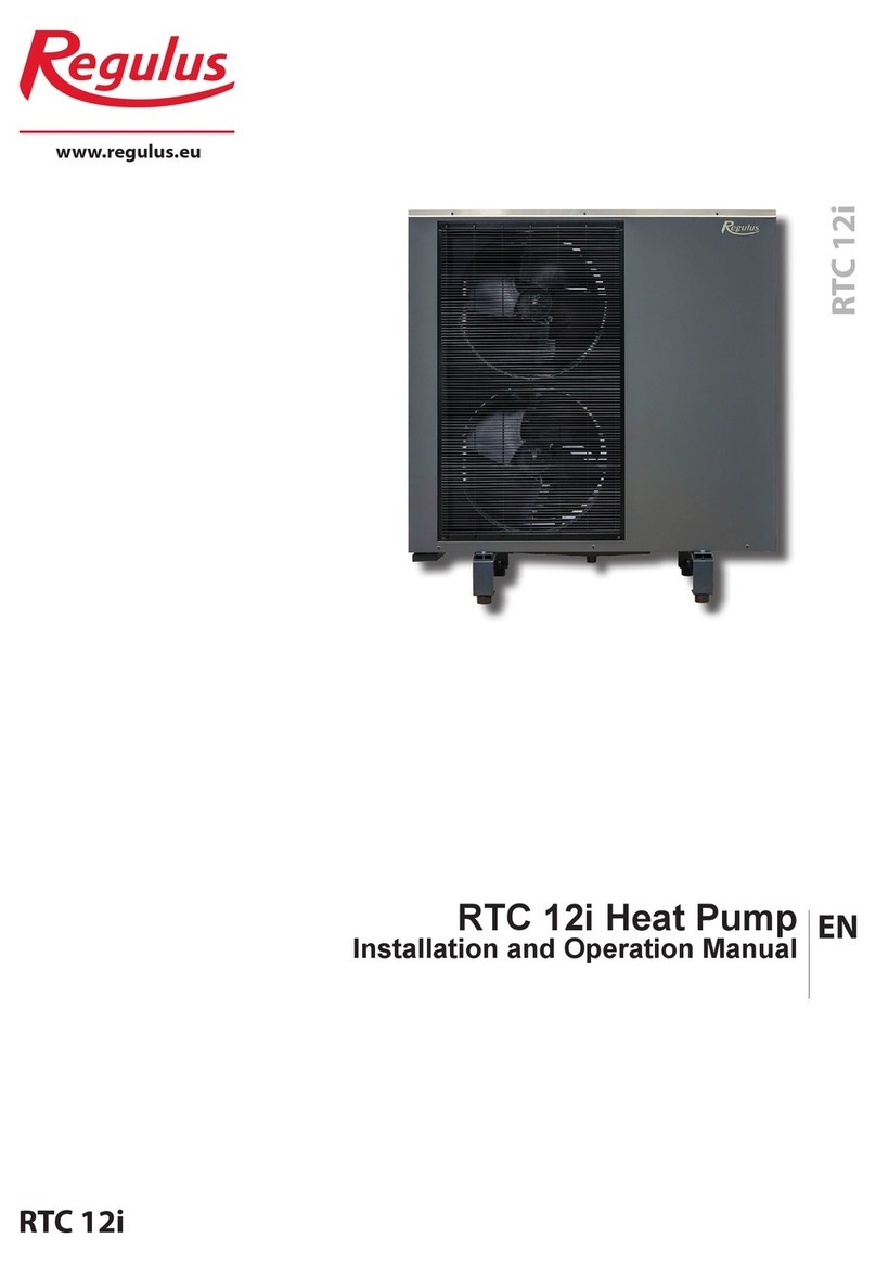
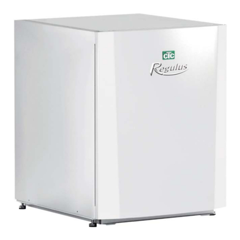
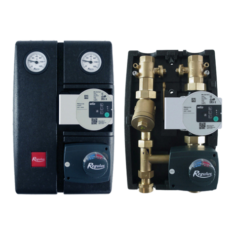
Regulus RegulusHBOX 212 RTC 3/1 User manual

www.regulus.eu
RegulusHBOX
RegulusHBOX
EN
Installation and Operation Manual
RegulusHBOX 212 RTC 3/1

│2
CONTENTS
A. GENERAL INFORMATION .......................................................................................................... 5
A1. Safety Instructions .......................................................................................................... 5
A2. Application, Description .................................................................................................. 5
A3. Components .................................................................................................................... 7
A4. Internal Hydraulic Connection .......................................................................................... 8
A5. Parameters ...................................................................................................................... 9
B. INSTALLATION, CONNECTION ............................................................................................... 11
B1. Dimensions .................................................................................................................... 11
B2. Installation Site Requirements ....................................................................................... 12
B3. Installation ..................................................................................................................... 13
B4. Hydraulic Connection .................................................................................................... 13
B4.1. Hydraulic Variant with one heating circuit ......................................................... 15
B4.2. Hydraulic Variant with two heating circuits ....................................................... 16
B5. Electrical Wiring ............................................................................................................. 17
B5.1. Cable Entry ...................................................................................................... 17
B5.2. Terminal Block ................................................................................................. 18
B5.3. Complete Inner Wiring Diagram ....................................................................... 19
B5.4. Wiring Diagram of M&R Peripherals to RegulusHBOX .................................... 20
B5.5. Connection and Adjustment of Optional Accessories - room sensor/unit, thermostat... 21
B6. Pre-commissioning Inspection ....................................................................................... 22
C. SETTINGS USING THE MAIN DISPLAY ................................................................................... 23
C1. Main menu ..................................................................................................................... 23
C1.1. Settings for HEATING ...................................................................................... 24
C1.2. Settings for HOT WATER ................................................................................. 24
C1.3. Settings for DHW RECIRCULATION ............................................................... 25
C1.4. Other settings .................................................................................................. 25
D. HOW TO SET ACCESS TO CONTROLLER WEBSITE ............................................................ 26
D1. How to connect the controller to a local network ............................................................ 26
D2. How to connect the controller to a PC directly ................................................................ 27
D3. How to connect via IR Client mobile application ........................................................... 28
E. SETTING THE CONTROLLER THROUGH WEB BROWSER .................................................. 29
E1. Home Screen (HOME) .................................................................................................. 29
E2. Tiles for Heating and Hot Water .................................................................................. 30
E3. Tiles for Hot Water Recirculation and Ventilation ........................................................... 30
E4. Display of the Diagram (DIAGRAM) ............................................................................... 31
E5. Heating Zone Menu (HEATING) .................................................................................... 31
E6. Heating Zone Settings (Zone 1 to 6) .............................................................................. 32
E6.1. Room Temperature Settings ............................................................................ 32
E6.2. Time Program Settings .................................................................................... 32
E6.3. Summer/Winter Fuction Settings...................................................................... 33

3 │
E6.4. Weather Compensating Heating Curve Settings ............................................ 33
E7. AKU Zone ...................................................................................................................... 35
E8. Pool Heating .................................................................................................................. 35
E9. Holidays ......................................................................................................................... 35
E10. DHW Menu (HOT WATER) .......................................................................................... 36
E10.1. Hot Water Heating by Heat Pump ................................................................. 36
E10.2. Hot Water Heating by Auxiliary Source .......................................................... 36
E11. Hot Water Recirculation Settings ................................................................................. 37
E12. Sources Menu (SOURCES) ........................................................................................ 37
E12.1. Heat Pump ..................................................................................................... 37
E12.2. Solar Heating ................................................................................................. 38
E12.3. Fireplace, Solid Fuel Boiler ............................................................................ 38
E12.4. RegulusHBOX Electric Heating Elements ...................................................... 39
E13. Other Settings Menu (OTHER) .................................................................................... 39
E13.1. Inputs and Outputs ......................................................................................... 39
E13.2. Access and Password .................................................................................... 39
E13.3. General Settings ............................................................................................ 39
E13.4. E-mail Notifications ........................................................................................ 39
E13.5. Function Overview ......................................................................................... 39
E13.6. Fault history ................................................................................................... 39
E13.7. HRV Zone ...................................................................................................... 39
E13.8. Universal Outputs .......................................................................................... 41
E13.9. RegulusRoute ................................................................................................ 41
E14. Manual Access Menu (MANUALS) .............................................................................. 41
F. ADJUSTING THE CONTROLLER THROUGH THE SERVICE DISPLAY .................................. 42
F1. Controller Input .............................................................................................................. 42
F2. Overview of Parameters Displayed on the Service Display ............................................ 42
F2.1. Basic Display ................................................................................................... 42
F2.2. Zone Display (zone 1, zone 2) .......................................................................... 43
F2.3. Solar Thermal System Display ......................................................................... 44
F2.4. Display of Hot Water Zone Heated by Auxiliary Source (DHW-E) ..................... 44
F2.5. Display of Hot Water Zone Heated by Heat Pump (DHW) ................................ 44
F2.6. Display of Heat Pump, Heat Pump Cascade (HP in series) .............................. 45
F2.7. Display with Firmware Version and Release Date ............................................ 46
F2.8. Controller in Factory Settings ........................................................................... 46
F2.9. Select the Desired Setting (menu) .................................................................... 46
F3. User Settings ................................................................................................................. 47
F3.1. Heating Zones .................................................................................................. 47
F3.2. HRV Zone ........................................................................................................ 47
F3.3. Time Programs ................................................................................................ 48
F3.4. Weather Compensating Heating Curves .......................................................... 48
F3.5. Heat Pump Control .......................................................................................... 48
F3.6. HP Faults ......................................................................................................... 48
F3.7. Other Faults ..................................................................................................... 48

│4
F3.8. Settings of DHW Heating by the Heat Pump (DHW-HP) .................................. 49
F3.9. Settings of DHW Heating by Auxiliary Source (DHW-E) ................................... 49
F3.10. Settings of Thermal Store Heating ................................................................. 49
F3.11. Settings of DHW Recirculation ....................................................................... 49
F3.12. Statistics ........................................................................................................ 49
F3.13. Operating Data ............................................................................................... 50
F3.14. Other .............................................................................................................. 50
F3.15. Date and Time Settings .................................................................................. 50
F3.16. RegulusRoute - Service Connection Parameters ........................................... 50
F4. Add-on Modules ............................................................................................................. 51
F4.1. Fire Module ...................................................................................................... 51
F4.2. UNI Module, UNI Module 2 ............................................................................... 51
G. MAINTENANCE ........................................................................................................................ 52
G1. Maintenance by the User ............................................................................................... 52
G2. Removing the Front Covers ........................................................................................... 52
G3. Removing the Wiring Cover ........................................................................................... 53
G4. Professional Maintenance ............................................................................................. 53
G5. Discontinuing Operation ................................................................................................ 54
G6. Recycling / Disposal ...................................................................................................... 54
H. SERVICING ............................................................................................................................... 54
H1. Fault Indication .............................................................................................................. 54
H2. Record of Repairs and Inspections ................................................................................ 55

5 │
A. GENERAL INFORMATION
This Installation and Operation Manual forms an integral part of the product. Before starting any
work, read this manual and keep it accessible at all times. Should you lose the manual, you can
download the current version in pdf format from the website www.regulus.eu.
A1. Safety Instructions
● This appliance should only be used by persons who have been properly instructed in the
safe use of the appliance and understand the risks involved. The appliance should not be
used by children and persons with limited physical, sensory or mental abilities or with
insufficient experience and knowledge. It is expressly forbidden for children to play with
the appliance!
● The hydraulic connection of RegulusHBOX shall be carried out by a professionally qualified
person in compliance with the applicable standards and regulations.
● Only persons with electrical qualification are permitted to remove the wiring cover.
● All electrical installation work must be carried out by a professionally qualified person, in accordance
with this Manual and in compliance with the applicable standards and regulations.
● Do not tamper with the internal wiring of RegulusHBOX, it is complete from the production.
● Before starting work on the electrical installation, it is necessary to disconnect RegulusHBOX
from the power supply!
● The controller integrated in RegulusHBOX in no way replaces the safety elements of the
heating system or the hot water system. These safety elements must be installed in accordance
with the applicable standards and regulations. Carry out the installation according to the design
and make sure all prescribed safety elements are installed.
● The setting of the controller and the connection of optional accessories must be carried out in
accordance with the instructions given in this manual.
A2. Application, Description
RegulusHBOX indoor unit is intended for space and DHW heating with a RTC single-phase inverter
heat pump.
The unit involves a combination thermal store (HSK type). DHW is heated continuously in a stainless-
steel heat exchanger. The tank is intended for heating systems with one or multiple mixed or unmixed
heating circuits. A solar thermal system can be connected through an optional solar module (kit with
a heat exchanger).

│6
The operation of RegulusHBOX and connected heating and hot water systems is controlled by a
built-in smart controller which comes completely electrically wired from the factory. This controller is
equipped with its own website (web server) permitting remote control through a web browser or from
a smartphone or tablet with the application Regulus IR client installed (versions for Android and iOS
are available).
RegulusHBOX involves a HSK combination thermal store with an integrated stainless-steel heat
exchanger for DHW heating, fitted with 2 heating elements of 12 kW total output, switched in 2 kW
steps.
Heat pump switching between the heating system and DHW heating is ensured by a three-way zone
valve with actuator.
Information on the current operating status can be read on the control unit with a graphical display
located on the front cover of RegulusHBOX. The connecting cable of the control unit is not
connected (to avoid being unintentionally torn out during installation). It needs to be connected
to its counterpart marked “Display” on the wiring compartment cover during installation. If necessary,
the control unit can be moved to the living area of the house where it can also act as a room
temperature and humidity sensor (using JYSTY 1x2x0.8 cable). In this case, a blanking plug shall be
installed instead of the control unit (code 18248 - not included in supply).
Basic elements of RegulusHBOX indoor unit
■ IR RegulusHBOX Controller with remote access from a computer or a mobile app.
■ Control unit with graphical display, English menu, that can be used as a room unit (two-wire
connection).
■ HSK combination thermal store of 210 l total volume, divided by a tight separating partition
in the ratio 49 l (heating), 140 l (DHW heating), 21 l (stainless-steel heat exchanger).
■ DHW heating in a stainless-steel heat exchanger, 6 sqm.
■ 12 kW heating elements, switched in 2 kW steps (max. output can be limited in the controller
menu).
■ Three-way zone ball valve for heat pump switching between space and DHW heating.
■ 12 l expansion vessel for heating system.
■ Waste pipe from safety valves incl. stench trap.
■ Electric wiring incl. terminal block for easy connection of a heat pump and other accessories incl.
basic element protection.
■ Heating water temperature and pressure sensor, DHW temperature sensor.
Accessories enclosed in the package
■ Heating system safety group incl. air vent valve, 3 bar safety valve, pressure gauge and T-piece
for topping up heating water / connecting a supplementary expansion vessel for case when the
integrated 12 l expansion vessel is not sufficient.
■ Safety kit for a cold water pipe incl. check valve, 8 bar safety valve, pressure gauge, T-piece for
connecting an expansion vessel/recirculation and T-piece for topping up heating water.
■ Outdoor temperature sensor.
■ Pump station for heat pump circuit with Wilo Para 25/8 iPWM1 circulation pump.
■ Ball valve w. filter & magnet.

7 │
The photo of the open RegulusHBOX shows its state with the
wiring cover removed.
1
2
3
4
5
6
8
9
11
13
12
15
14
16
17
18
20
19
21
23
24
25
26
27
28
1 – Pump station of the heat pump circuit
- included in supply
2 – Heating system safety group (3bar
safety valve, air vent valve, pressure
gauge, T-piece with a drain valve
designed for heating system topping
up) - included in supply
3 – Cold water safety kit (G3/4“F shutoff
valve for connecting cold water supply,
check valve with service valve, cold
water safety valve 8 bar, drain valve
used also for topping up the heating
system, pressure gauge, T-piece for
connecting DHW recirculation /
expansion vessel) - included in supply
4 – P-trap w. stench trap
5 – Terminal block
6– Circuit breaker for measurements
&control (B6A 1p) and heat pump
circuit breaker (B20A 1p)
7 – Heat pump contactor
8 – IR RegulusHBOX controller
9 – Control unit connector
10 – Label w. serial number
11 – Safety thermostat
12 – Pressure sensor for pressure
monitoring in heating system
13 – Expansion vessel service valve
14 – 12l heating system expansion vessel
15 – DHW control sensor
16 – Inlet for solar module
17 – Safety thermostat sensor
18 – 2x6 kW electric heating elements
19 – Expansion vessel valve
20 – Outlet for solar module
21 – Heating system pump station (not
included in supply)
22 – Cable glands
23 – Power supply for IR
24 – Auxiliary internal terminal block
25 – Contactor for electric heating
elements
26 – Three-way zone valve for switching
between space and DHW heating
27 – G1/2“M drain valve of heating system
and thermal store
28 – Adjustable feet for levelling
RegulusHBOX
29 – Pt1000 outdoor temperature sensor
- included in supply
30 – Pt1000 temperature sensor for
heating water, w. 4m long cable
- connected, placed in cable gland
31 – Ball valve with filter and magnet
(marked MFB in the hydraulic
connection diagram) - included in
supply
32 – Communication cable
7
31 29 30
2
3
10
22
32
A3. Components

│8
A4. Internal Hydraulic Connection
SV – cold water
TV – hot water
CV – hot water recirculation
UT1 – central heating (heating system)
KK – ball valve
ETT – 6kW electric heating element
OČ-TC – circulation pump of heat pump
OČ-UT – circulation pump of heating circuit
MIX – mixing valve for heating system
PV-UT – safety valve for heating system
PV-TV – safety valve for DHW
EXP-UT – heating system expansion vessel, 12 l
(integrated)
EXP1-UT – heating system additional expansion vessel
(optional)
EXP-TV – DHW expansion vessel (optional)
TRV – three-way zone ball valve
ZV – check valve
AOV – automatic air vent valve
REDV – pressure reducing valve (optional)
VK – drain valve
MFB – Magnet Filterball
MF – filter with magnet
ZKV – check valve test valve
SOL – points for connecting another heat source (e.g. a
solar module)
BRAIDED HOSE
COMPENSATOR
KEY
CH – flow
CH – return
Included in HBOX supply Optional accessories

9 │
A5. Parameters
Technical Data
Total tank volume 210 l
Total uid volume in tank 189 l
Fluid volume above the separating metal sheet 140 l
Fluid volume below the separating metal sheet 49 l
Fluid volume in DHW heat exchanger 21 l
DHW heat exchanger surface area 6 m2
Fluid working temperature 5–90 °C
Max. working pressure – heating system 3 bar
Min. working pressure – heating system 0.5 bar
Max. working pressure – DHW 8 bar
Ambient temperature 5–40 °C
Max. relative humidity 80 %, non condensing
Safety valve set pressure – heating system 3 bar
Safety valve set pressure – DHW 8 bar
Safety valves seat cross section 132 mm2
Safety valve discharge coecient 0.3
3-way valve actuator run time 15 s
Heat loss 160 W
Total weight without water 148 kg
Total weight with water 360 kg
Overall dimensions (W x H x D) 595 x 1725 x 650 mm
Tipping height (without pump stations and safety groups
connected) 1790 mm
Electric Data
Power supply 3/N/PE ~ 400 / 230 V 50 Hz
Max. cross section of power cable 4 mm2
Nominal power input 12.2 kW (without a heat pump connected)
Heating elements 2 x 6 kW (3 x 2 kW – each 230 V)
IP rating IP20
Circuit breaker for heat pump B16A 3p
Circuit breaker for measurement and control B6A 1p
B20A 1p

│10
[m H2O]
P1 [W]
Wilo Para 25/8 iPWM1 pump performance curves
Pressure Drop Diagram - heating
Q [l/min]
Δp [bar]
Δp [m H2O]
Q [l/h]
_____
Tepelné čerpadlo
_ _ _ _ Otopný systém
Pressure Drop Diagram - DHW
p
indoor piping to connect HP
indoor piping to connect central
heating
- PWM signal

11 │
B. INSTALLATION, CONNECTION
B1. Dimensions
Pos. Description
Connection Height [mm]
W1 Cold water G 3/4" F 1755
W2 Hot water G 3/4" M 1700
B1 Incoming from heat pump G 1" M 1700
B2 Return to heat pump G 1" M 1700
H1 Flow to heating system G 1" M 1700
H2 Return from heating system G 1" M 1700
P1 Safety group – heating system G 1" M 1705
P2 Safety kit – DHW G 3/4" Fu 1725
P3 Waste pipe from safety valves hose DN 20 1600
X1
Incoming from solar thermal system (optional)
G 3/4" M 1700
X2
Return to solar thermal system (optional)
G 3/4" M 1700
Tipping height 1790 mm
(without pump stations and safety groups connected)

│12
B2. Installation Site Requirements
● RegulusHBOX shall be installed indoors only.
● Ensure that no water can enter RegulusHBOX at the installation site.
● Do not install the device in areas with a bath or shower in zones 0, 1 and 2.
● Do not install RegulusHBOX at places with a risk of freezing.
● Do not install the device near aggressive, explosive or ammable gases, objects or substances.
● Observe the minimum required clearances from the constructions according to the picture - Re-
gulusHBOX is designed to be installed also in a narrow space.
Installation with pump stations Installation without pump stations (low
ceiling)
595
650 700
2088 300
595
650
300
700
1871
2388
2171

13 │
B3. Installation
Transport RegulusHBOX to the installation site in a vertical position. It is not permitted to
transport RegulusHBOX in a horizontal position.
Install RegulusHBOX on a level floor with sufficient
floor loading capacity - the weight of RegulusHBOX
without heating water is 148 kg, with water it is
360 kg.
Level RegulusHBOX vertically using its adjustable
feet.
B4. Hydraulic Connection
A. The pipe connection outlets are marked with the respective pictograms
on the upper side of RegulusHBOX.
1- G 1“ M return from heating system
2- G 1“ M flow to heating system
3- G 1“ M incoming from heat pump
4- G 1“ M return to heat pump
5- G 3/4“ M hot water
6- G 1“ M heating system safety group
7- G 3/4“ F cold water safety cold water
connection
8- Waste pipe from safety valves, DN 20 hose
(from the rear)
9- Passages for connecting an optional
solar module
B. Installation of the enclosed accessories:
1- mount the pump station with the circulation pump of the
heat pump circuit on connections 3 and 4 (G1“M). Install a
ball valve with filter and magnet (marked MFB on the hydrau-
lic connection diagram) in an easily accessible place of the
return pipe to the heat pump. The pump station includes a
Wilo Para 25/8 iPWM1 circulation pump, two ball valves and
two thermometers. Cables with a connector for power supply
and control of the circulation pump are factory-connected to
the main terminal block. To connect the circulation pump, it is
enough to remove the cables from the cable passage where
they are stored and connect the connectors to the pump.
1 2 3 4 5
6
7
8
9

│14
C. Connection to system
Connect RegulusHBOX to the system according to the hydraulic connection diagram:
1 - Connect the pump station of the heating system or the manifold in the case of connecting
several heating circuits to connections 1 and 2 (G 1“M). A heating water temperature sensor is
connected to terminal A/DI14 of the motherboard; it is stored in the cable passage. Place this
sensor in the sheath in the pump station or in the flow pipe to the heating system.
2 - connect the cold water supply to the G 3/4“F port of the ball valve in the cold water safety kit
3 - connect the hot water outlet to the connection 5 (G 3/4“M)
4 - connect the waste pipe to hose 8 (DN20). The waste pipe from the safety valves is equipped
with a stench trap from the factory.
5 - after removing the lid, it is possible to connect the DHW expansion vessel or the circulation
pump station to the G 3/4“M socket of the cold water safety kit. When connecting both the
expansion tank and the pump station, connect them using a T-piece.
6 - if the 12 l built-in expansion vessel is not sufficient, connect an additional expansion vessel of
the heating system - remove the drain valve under the safety group, add a T-piece, connect the
pipe to the expansion vessel and re-install the drain valve.
2- mount the safety group of the heating system with the
T-piece and G 1/2“ valve on the connection 6 (G 1“ M),
connect the waste from the safety valve to the drain tundish
located in the cover of RegulusHBOX. The safety group
involves a safety valve, air vent valve and pressure gauge.
The G 1/2“ valve is intended for topping up the heating
system.
3 - mount the cold water safety kit on the pipe 7 (Cu 18 mm
with G 3/4“ union nut), connect the waste from the safety
valve to the drain tundish located in the cover of Regu-
lusHBOX. The safety kit involves a shut-off valve, check
valve with service valve, safety valve, pressure gauge and
G 1/2“ drain valve that is intended also for topping up the
heating system. Cold water from the mains

15 │
B4.1 Hydraulic Variant with one heating circuit
KEY
1 – Regulus heat pump (RTC, CTC)
2 – HBOX indoor unit (RTC, CTC)
3 – additional heating system expansion vessel (optional – integrated 12l one is included)
4 – DHW expansion vessel (optional)
5 – safety kit for combination thermal store (included in HBOX supply)
6 – pump station for DHW recirculation – CSE TV ZV (optional)
7 – safety group for heating system (included in HBOX supply)
8 - pump station for heat pump (included in HBOX supply)
9 - pump station for heating system (not included in supply – needs to be chosen)
SV – cold water
TV – hot water
CV – hot water recirculation
ÚT – central heating (heating system)
KK – ball valve
ZV – check valve
AOV – automatic air vent valve
REDV – pressure reducing valve (optional)
VK – drain valve
SVE – expansion vessel service valve
PV-ÚT – safety valve for heating system
MFB – Magnet Filterball
BRAIDED HOSE
COMPENSATOR

│16
B4.2 Hydraulic Variant with two heating circuits
KEY
1 – Regulus heat pump (RTC, CTC)
2 – HBOX indoor unit (RTC, CTC)
3 – additional heating system expansion vessel (optional – integrated 12l one is included)
4 – DHW expansion vessel (optional)
5 – safety kit for combination thermal store (included in HBOX supply)
6 – pump station for DHW recirculation – CSE TV ZV (optional)
7 – safety group for heating system (included in HBOX supply)
8 - pump station for heat pump (included in HBOX supply)
9 - pump station for heating system2 (not included in supply – needs to be chosen)
10 – pump station for heating system1 (not included in supply – needs to be chosen)
11 – heating system collector/manifold
SV – cold water
TV – hot water
CV – hot water recirculation
ÚT1 – central heating (heating system) – circuit 1 – unmixed
ÚT2 – central heating (heating system) – circuit 2 – mixed
KK – ball valve
ZV – check valve
AOV – automatic air vent valve
REDV – pressure reducing valve (optional)
VK – drain valve
SVE – expansion vessel service valve
PV-ÚT– safety valve for heating system
MFB – Magnet Filterball
BRAIDED HOSE
COMPENSATOR

17 │
B5. Electrical Wiring
B5.1. Cable Entry
For the electrical connection of the RegulusHBOX, it is necessary to remove the upper front cover
and the wiring cover located below it.
Two passages under the lid of the RegulusHBOX
are used to connect cables
Note: The power supply cable is used
not only to supply RegulusHBOX, but
also to supply the heat pump! Under
normal conditions, it is recommended to prefer
the cross-section of the copper conductors of the
power supply cable 4 mm2.
We do not recommend the use of wire ferrules when connecting the maximum cross-section of the
stranded wire to the connection terminal block. Wire ferrules are suitable for wires with a smaller
cross-section (typically sensors, PWM, etc.). Minimum stripping length 9 mm.
After closing the wiring cover, it is necessary to connect the control unit connector before retting the
top cover.
Before opening the wiring cover,
unscrew the two screws
LIFT
1
2

│18
Universal outputs K5 and DO24-DO27 have no default function. The devices switched from these
outputs need to be set on the service level of the controller.
B5.2. Terminal Block
IUT
IUT
OUT
OUT
B
A
EP
N
RI2L
EP
N
L3
L2
L1
EP
N
CT3L
NODH
464
2,5
9
mm
2,5 max. mm
2
max. mm
2
1,5
42,5
EP
N
K5
4WP
WPi
-BIC
+BIC
DNG
3WP
DNG
N
EP
42OD
EP
EP
N
52OD
N
62OD
N
EP
72OD
SIGNÁL HDO
HLAVNÍ PŘÍVOD
NAPÁJENÍ TČ
NAPÁJENÍ OBĚHOVÉHO ČERPADLA TČ - PŘIPOJENO
UNIVERZÁLNÍ RELÉ
OVLÁDÁNÍ OBĚHOVÉHO ČERPADLA TČ - PŘIPOJENO
OVLÁDÁNÍ EXTERNÍHO VOLITELNÉHO ČERPADLA
SBĚRNICE CIB
KOMUNIKACE S TČ
RIPPLE CONTROL
SIGNAL
MAINS
HP POWER
SUPPLY
SUPPLY OF HP CIRCULATION PUMP - CONNECTED
CONTROL OF HP CIRCULATION PUMP - CONNECTED
UNIVERSAL RELAY
CONTROL OF OPTIONAL EXTERNAL PUMP
CIB BUS
COMMUNICATION W. HP

19 │
B5.3. Complete Inner Wiring Diagram
PE PE2
PE1
NN7
NN1
L2 IR
L2 IR
IRL-7
IRL-6
L2 IR
2
1
4
3
2
1
4
3
6
5
8
7
2
1
4
3
6
5
8
7
10
9
12
11
N6
IRL-5
IRL-8
IRL-3
IRL-4
IRL-2
IRL-1
PE
6
5
8
7
N
9
12
11
L3 PL3-3
PL3-2
L2 PL2-3
PL2-2
L1
2
1
4
3
6
5
8
7
10
9
12
11
A2
14
A1
13
6
5
4
3
2
1
TK2
GND2 H3
PL1-3
PL2-3
PL3-3
N4
L
NV-
V+ 24V
GND1
N3
IRL-2
DO0-1
DO0-2
DO2-1
DO2-2
DO4-1
DO4-2
DO6-1
DO6-2
DO8-1
DO8-2
DO10-1
DO10-2
K1
K2
IRL-3
K4
K5
IRL-4
IRL-5
HDO N
GND1
24V
GND2
H3 GND5
H4
iPWM
PWM3
PWM4
GND6
TL IN
GND3
TL OUT
TxRx+
TxRx-
CIB-
DISP-
CIB+
DISP+
ETH2
C
1
TERMOSTAT /
K1
TK1
DISP- DISP+
DO27
DO26
DO25
DO24
IRL-7
GND
+5V
PWM4
PWM3
AI20
AI19
COM9
GND
TCL2+
TxRx -
TxRx+
+24V
GND
DI18
K6
K5
K4
K3
K2
K1
L9
L8
L7
L6
L5
L4
L3
M9
M8
M7
M6
M5
M2
M1
L2
L1
M4
M3
CIB+
CIB-
TCL2-
D5
D4
D3
D2
GNDS
AO5
AO4
AO3
AO2
AGND
AO1
AO0
A/DI17
A/DI16
A/DI15
A/DI14
A/DI13
A/DI12
GND
GND
GND
GND
GND
GND
A/DI11
A/DI10
A/DI9
A/DI8
A/DI7
A/DI6
GND
GND
GND
GND
GND
GND
A/DI5
A/DI4
A/DI3
A/DI2
A/DI1
A/DI0
GND
GND
GND
GND
GND
GND
DO25
COM
DO24
COM
COM
DO26
COM
DO27
PL1-3
PL1-2
10
GNDS
ETH1
DO6-1
DO8-1
DO10-1
DO0-1
DO2-1
DO4-1
PE
PE3
N5
N3
N8
GND4
F4
2
1
TT TK2TK1
N4
N2
PE4
4
4
02/2023 - HBOX 12 RTC 3/1s - v1.2
L1
signal AI
signal DI
GND AI/DI
N
PE
L2
L3
+24VDC
-24VDC
CONCECTOR DISP.
KONEKTOR DISPLEJE /
DESKA ŘÍDICÍCH SPOJŮ REGULUSHBOX /
CONTROL UNIT REGULUSHBOX
ZDROJ 24VDC / POW.SUPP. 24VDC
STYKAČ /
CONTACTOR
ODEPÍNAČ STYKAČE /
DISCONN. CONTACTOR
HDO N
HDO N
TC L3
N
PE
TC L3
N2
L2 IR
N
PE
IRL-6
iPWM
GND
iPWM
GND3
CIB+
CIB-
CIB+
CIB-
A
B
TUI
A
B
TUI
K5
N
K5
2
1
B6/1
DO24
N
PE
DO24
DO25
N
PE
DO25
DO26
N
PE
DO26
DO27
N
PE
DO27
PL3-4
PL2-2
N7
L3
N
PE
PL3-1
N1
L2
PL2-1
L1
PL1-1
PE1
PE
PWM4
PWM4
PWM3
PWM3
GND
PL3-2 PL3-1
IRL-1
44
A2
A1
2
1
TC L3
K4
PL3-4
N8
2
1
B20/1
PL2-1
N8
GND7 TUI
TUO TUO
TUO
TUO
GND7 TUI
THERMOSTAT
CIRC.BREAK. MAR
JISTIČ MAR /
CIRC.BREAK. HP
JISTIČ TC /
STYKAČ TC /
CONTACTOR HP
TLAKOMĚR /
T.ČIDLO AKU /
AKUMULAČNÍ NÁDRŽ /
ZONE VAL. HW
ZÓN. VENT. TV /
THERMAL STORE
TOP. TĚL. 2 /
HEAT. ELEM. 2
TOP. TĚL. 2 /
HEAT. ELEM. 2
PRESS.SENS.
T.SENS. TH. STORE
T.ČIDLO TV / T.SENS. DHW
L3
N
PE
L2
L1
OUT
GND
p
IN
AI
GND
PE4
N6
DO4-2
DO2-2
DO0-2
H4
GND5
TL OUT
GND6
TL IN
AI
GND
F6
GND7
L-T
L
N
3
1
2IRL-8
N5
K2
L3
N
PE
L2
L1
PE3
N5
DO10-2
DO8-2
DO6-2
PE
AI
GND
F4
GND4
T.ČIDLO UT1 / T.SENS. HC1
GND7
F6
HLAVNÍ PŘÍPOJNÁ SVORKOVNICE / MAIN TERMINAL
PE
L
N
GND
PWM
iPW
MOLEX
MOLEX
(SOUČÁST ČERP. SKUP. V PŘÍBALU /
OBĚH.ČERP.TC / CIRC.PUMP.HP
(PART OF ENCLOSED PUMP GROUPE
IN ACCESSORIES)

│20
B5.4. Wiring Diagram of M&R Peripherals to RegulusHBOX
HLAVNÍ
ROZVADĚČ
OBJEKTU
HDO N
A/DI5
A/DI4
A/DI3
A/DI2
A/DI1
A/DI0
GND
GND
GND
GND
GND
GND
PE
N
L1
PE
N
CIB+
CIB-
TUI
TUO
TUO
CI-
CI+
POK. JEDNOTKA
CIB
CIB
AI
GND
ČIDLO TEPLOTY
VENKOVNÍ
AI
GND
ČIDLO TEPLOTY
POKOJOVÉ
REGULUSHBOX RTC
DESKA ŘÍDÍCÍCH SPOJŮ
REGULUSHBOX
JISTIČ
TECHNOLOGIE
VYTÁPĚNÍ
JYTY 4Dx1
JYTY 4Dx1
CYKY 5Jx6
CYKY 3Dx1,5
JE NAZNAČENO ZAPOJENÍ POUZE NOVÝCH
EXTERNÍCH ZAŘÍZENÍ. ZAPOJENÍ STÁVAJÍCÍCH
ZAŘÍZENÍ, KTERÁ JSOU V REGULUSHBOX JIŽ
ZAPOJENA Z VÝROBY, JSOU ZACHOVÁNA!
L2
L3
PWM3
GND
SVORKOVNICE PRO PŘIPOJENÍ
zel.
červ.
TEPLOTNÍCH ČIDEL
DO27
N
PE
VÝSTUP NAPÁJENÍ TC
VSTUP NAPÁJENÍ HBOX
VSTUP SIGNÁLU HDO
KOMUNIKACE TC
ZAŘÍZENÍ CIB
TRVALÝ
VÝSTUP
VOLITELNÝ
PWM
VÝSTUP
230V
A/DI11
A/DI10
A/DI9
A/DI8
A/DI7
A/DI6
GND
GND
GND
GND
GND
GND
5 x VÝSTUP 230V SPÍNANÝ VOLITELNÝ
05/2023 - HBOX 12 RTC 3/1s - v1.2
L3 TC
LAN
UTP CAT5E
TEPELNÉ ČERPADLO
RTC
PWM4
GND
iPWM
DO26
N
PE
DO25
N
PE
DO24
N
PE
K5
N
PE
L2 IR
N
PE
ETH2
JYSTY 1x2x0,8
CYKY 3Jx1,5
JYTY 4Dx1
PE
N
L
GND
iPWM
PWM
ČERPADLO TC
OBĚHOVÉ
LiYCY TP 3x2x0,75
CYKY 3Jx4
KABELY PRO OBĚHOVÉ ČERPADLO TC
JSOU DO SVORKOVNICE ZAPOJENY Z VÝROBY
NAPÁJENÍ OČ TC
ŘÍZENÍ OČ TC
A
B
TUI mod.
hně.
bíl.
TUO
TUO
TUI
TUI
A
B
G
hně.
bíl.
mod.
červ.
zel.
PE
N
L
HL
HN
PE
WIRING OF ONLY NEW EXTERNAL DEVICES IS
SHOWN. WIRING OF EXISTING DEVICES THAT
ARE ALREADY FACTORY-CONNECTED INSIDE
REGULUSHBOX IS MAINTAINED!
CABLES FOR HP CIRCULATION PUMP ARE
FACTORY-CONNECTED TO THE TERMINAL
BLOCK.
RTC HEAT PUMP
MAIN
DISTRIBU-
TION
BOARD OF
BUILDING
HEATING
TECHNOLOGY
CIRCUIT
BREAKER
HP
CIRCULATION
PUMP
CIB
ROOM UNIT
OUTDOOR
TEMPERATURE
SENSOR
RIPPLE CONTROL
SIGNAL INPUT
POWER SUPPLY INPUT
FOR HBOX
POWER SUPPLY
OUTPUT FOR HP
230V
OUTPUT
PERMA-
NENT
5x OUTPUT 230V SWITCHED, OPTIONAL
CONTROL OF HP
CIRCULATION PUMP
PWM
OUTPUT
OPTIONAL
CIB DEVICE
BOARD W. CONTROL TERMINALS
TERMINAL BLOCK FOR CONNECTING
TEMPERATURE SENSORS
ROOM
TEMPERATURE
SENSOR
HP COMMUNICATION
POWER SUPPLY OF
HP CIRCULATION
PUMP
green
white
brown
green
white
brown
red
blue
red
blue
This manual suits for next models
2
Table of contents
Other Regulus Heat Pump manuals
Popular Heat Pump manuals by other brands

Ariston
Ariston NIMBUS PLUS S NET manual

Enertech
Enertech BS018 Installation & operation manual

Immergas
Immergas MAGIS M4-30 Use and installation

Grundfos
Grundfos DSS Installation and operating instructions

Nibe
Nibe Fighter 2005 Service instruction

Guardian
Guardian PLATINUM Series Installation & operation manual