Regulus RTC 6i Manual

www.regulus.eu
RTC 6i
RTC 6i
EN
Installation and Maintenance Manual
RTC 6i
Inverter Air-to-Water Heat Pump

│2
RTC 6i - www.regulus.eu
CONTENTS
GENERAL OPERATING INSTRUCTIONS ......................................................................... 3
SAFETY INSTRUCTIONS .................................................................................................. 3
1. TECHNICAL DATA .......................................................................................................... 4
1.1. Sound data (by EN 12 102) ............................................................................... 4
1.2.Energyeciency............................................................................................... 4
1.3.Performancedata.............................................................................................. 5
1.4. Heat pump pressure drop .................................................................................. 6
1.5.Dimensions........................................................................................................ 6
2. CONNECTION VARIANTS ............................................................................................. 7
2.1.Directconnectiontoaheatingsystem,DHWheatinginahotwaterstoragetank.... 7
2.2.Connectionwithathermalstore(combinationwithotherrenewableheatsources) 7
2.3.Heatingsystemusedforcooling........................................................................ 7
3. CONSTRUCTION READINESS & INSTALLATION ....................................................... 8
3.1.Scopeofsupply................................................................................................ 8
3.2.Installationpreparationandtransport............................................................... 8
3.3.Minimumdistances........................................................................................... 9
3.4.Placementoftheheatpump............................................................................. 10
3.5.Condensatedrain............................................................................................. 11
3.6.Pipeinstallation................................................................................................ 12
3.7.Electricalwiring................................................................................................ 13
3.8.AddressingHPinacascade.............................................................................. 13
4. COMMISSIONING ......................................................................................................... 14
4.1.Initialstartup.................................................................................................... 14
5.MAINTENANCEANDSERVICING................................................................................. 15
5.1.Usermaintenance............................................................................................. 15
5.2.Professionalmaintenance................................................................................. 15
5.3.Faultdiagnosis.................................................................................................. 15
5.4.Refrigerantcircuitdiagram................................................................................ 16
5.5.Componentplacement...................................................................................... 17
5.6.Internalwiringdiagram...................................................................................... 18
5.7.Faultconditionsandtheirpossiblecauses........................................................ 19
6. RELATED DOCUMENTATION ........................................................................................ 22
7. DECOMMISSIONING ..................................................................................................... 22
8. RECYCLING / DISPOSAL .............................................................................................. 22
9.RECORDOFREPAIRSANDINSPECTIONS................................................................ 23

3 │
RTC 6i - www.regulus.eu
GENERAL OPERATING INSTRUCTIONS
Readthismanualcarefullybeforeoperatingandkeepitataneasilyaccessibleplaceforfuture
reference.Ifneeded,themanualcanbedownloadedinpdfformatfromhttp://www.regulus.eu/,or
obtainedfromthecompanyandprinted.Ifyouhaveanydoubtsoruncertainties,pleasecontactyour
equipmentsupplierortechnicalsupportofRegulus.
SAFETY INSTRUCTIONS
- Thedesign,location,hydraulicandelectricalconnectionsmustbedesignedbyaspecialistin
accordancewiththeapplicableregulations.
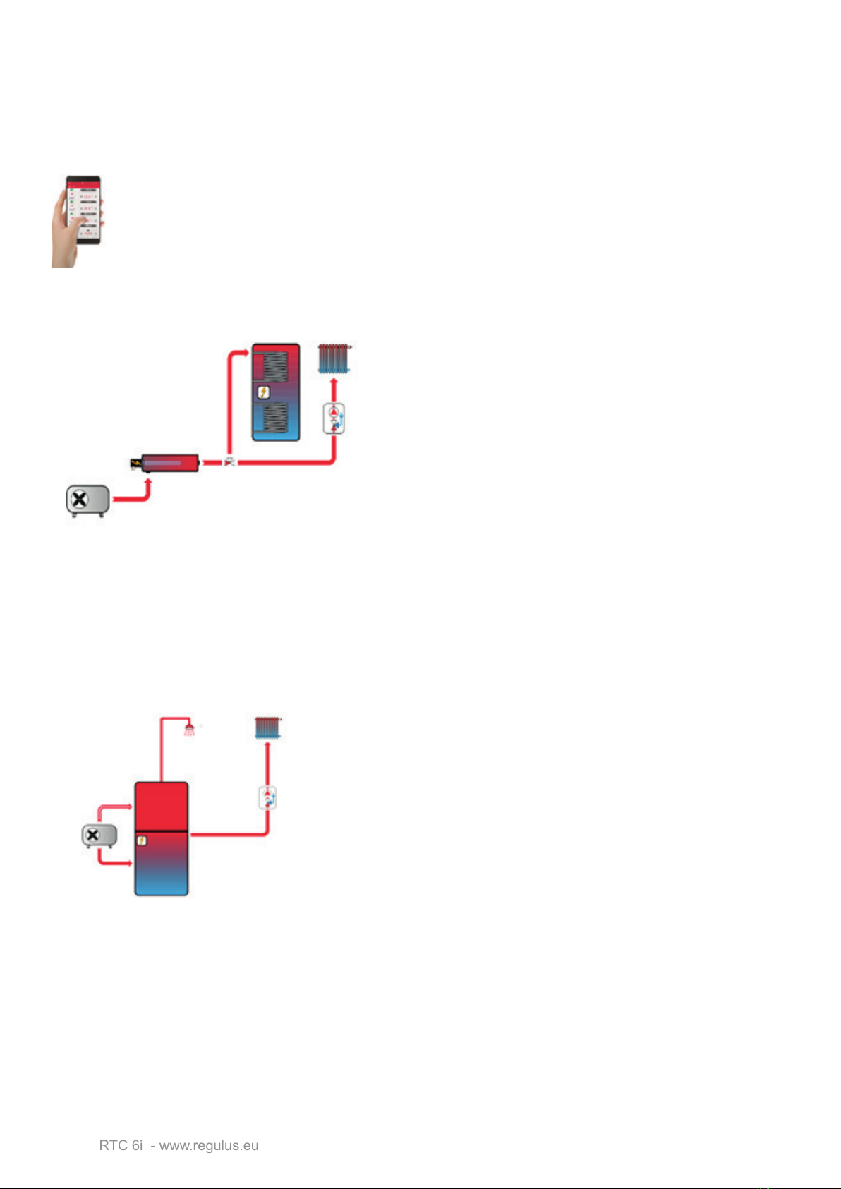
- Theequipmenthasbeendesignedforheatingorcoolingofheatingwater.Otheruses,unless
specicallyauthorisedbythemanufacturer,isnotpermitted.Heatingwateroramixtureof
waterwithglycolorglycerinebasedantifreezemaybeusedasaheattransfermedium.
- Theheatpumpshallbesecurelyearthed.
- Respecttheoperatinglimitsoftheequipment.
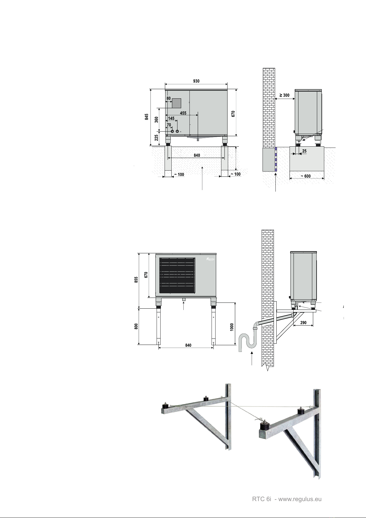
- The device is designed for outdoor installation. However, avoid installation in areas with
excessivedustorhumidity-suchasnearthehoodoutlet,etc.
- Theappliancemustbelocatedinanopenareawherethereisnoobstructiontotheowof
intakeorexhaustair.
- Theappliancemustnotbelocatednearopenamesorsourcesofignition.
- The equipment shall not be operated in an environment with explosive or chemically
aggressivegasesandsubstances.
- Allworkmustbecarriedoutbyprofessionalandqualiedsta.
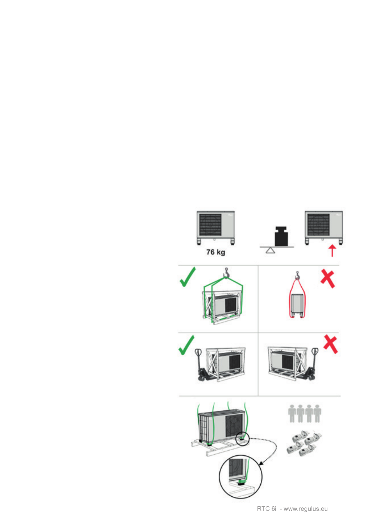
- Whenhandlingtheheatpumpwithacraneorotherliftingequipment,makesurethatthe
liftingdevices,lugs,etc.arenotdamaged.Neverstepundertheliftedload.
- Wearpersonalprotectiveequipment(goggles,gloves,etc.)
- Theequipmentcannotbeusedbychildrenandpersonswithreducedphysical,sensoryor
mentalabilities,orbyuntrainedpersonswholackthenecessaryknowledge.
- Ensurethattheheatpumpisswitchedobeforeanyintervention.
- Itisforbiddentocarryoutmaintenanceorcleaningwhentheequipmentislive.
- Itisforbiddentotouchtheequipmentbarefootorwithwetbodyparts.
- Donotspraywaterorotherliquidsontheequipment.
- Theequipmentcontainsrapidlyrotatingparts.Therefore,donotpushanyobjectsintothe
device.
- Theheatexchangerlamellasaresharpandcancauseinjury.
- Somepartsoftheequipment(e.g.thecompressoranditsoutletpipes)maybeveryhoteven
afterstoppingoperation.
- Itisforbiddentostandonthedevice,sitonitorplaceobjectsonit.
- Itisforbiddentopull,twistordisconnecttheelectricalcablesconnectedtotheequipment.
- Neverdisassemblecasing,covers,etc.thatareboltedtogether.
- Neverdisablesafetyfeaturesoftheequipment.
- Donotinterferewiththerefrigerantcircuitorelectricalwiring.Serviceworkmustonlybe
carriedoutbyanauthorisedserviceorganisation.
- Adamagedpowercablemayonlybereplacedbyanauthorizedserviceorganization.
- Itisforbiddentoleavethepackagingmaterialwithinreachofchildren,asthismayposea
dangertothem.
- It is forbidden to tamper with or replace any parts of the equipment without the express
permissionofthemanufacturer.
- Iftheseinstructionsarenotfollowedduringinstallation,operationandmaintenanceofthe
system,themanufacturerdoesnotfeelboundbythetermsofthewarranty.

│4
RTC 6i - www.regulus.eu
1. TECHNICAL DATA
Heatingoutput¹ 6.21kW
Powerinput¹ 1.53kW
COP¹ 4.06
Steadycurrent 7.0 A
Startingcurrent 2.4 A
Nominalcurrent 12 A
Powersupply 1/N/PE~230V50Hz
Recommendedcircuitbreaker B16A 1f
IPrating IPX4
Max.owtemperaturefromHP 55°C
Max.heatingwatertemperatureatHPinlet 100°C
Max.workingpressureofheatingwater 3 bar
HeatingwatervolumeinHP 4.5l
Min.volumeofheatingsystemthatcannotbeshuto 60l
Min.owratethroughHP 680l/h
Min.surfaceareaofheatexchangerinHWstorage
tank
1 m²
Airworkingtemperatureforheatingmode –25to45°C
Airworkingtemperatureforcoolingmode 0to55°C
Max.airowrate 2700m³/h
Number of fans 1
Fan speed variable
Max.fanpowerinput 65W
Compressortype/oil twinrotary/FV50S
Refrigerant R410A(GWP2088)
Refrigerantquantity 1.30kg
CO2equivalent² 2.71 t
Max.refrigerantworkingpressure 42 bar
Connections G 1"
Weight 66kg
1for temperatures A+7/W35 at max. speed
2not subject to mandatory leak checks under EU Regulation No. 517/2014
1.1. Sound data (by EN 12 102)
Soundpowerlevel 57dB(A)
Soundpressurelevelat5mdistance 38 dB(A)
Soundpressurelevelat10mdistance 32 dB(A)
1.2. Energy Eciency
Seasonalspaceheatingenergyeciency 176%
EnergyEciencyClass A+++
SCOP 4,47
For low-temperature applications under average climatic conditions

5 │
RTC 6i - www.regulus.eu
1.3. Performance data
HEATING
Speed Air temperature Flow temperature Output [kW] Power input [kW] COP [-]
85 Hz
7 °C
35 °C 5.42 1.44 3.77
45 °C 5.17 1.71 3.02
55 °C 4.89 2.04 2.40
2 °C
35 °C 5.30 1.42 3.75
45 °C 5.03 1.66 3,03
55 °C 4.84 1.94 2.49
-7 °C
35 °C 4.03 1.31 3.09
45 °C 3.46 1.45 2.39
55 °C 3.48 1.78 1.95
-15 °C
35 °C 3.16 1.21 2.62
45 °C 2.90 1.38 2.10
55 °C 2.62 1.63 1.61
50 Hz
12 °C
35 °C 3.71 0.75 4.98
45 °C 3.48 0.94 3.69
55 °C 3.75 1.15 3.25
7 °C
35 °C 3.24 0.75 4.33
45 °C 3.10 0.93 3.35
55 °C 2.81 1.11 2.53
2 °C
35 °C 3.15 0.75 4.23
45 °C 2.82 0.91 3.12
55 °C - - -
-7 °C
35 °C 2.27 0.72 3.14
45 °C 2.01 0.85 2.38
55 °C 1.79 1.00 1.79
-15 °C
35 °C 1.72 0.69 2.50
45 °C - - -
55 °C - - -
36 Hz
12 °C
35 °C 2.73 0.53 5.20
45 °C 2.47 0.67 3.71
55 °C 2.62 0.83 2.63
7 °C
35 °C 1.60 0.50 3.25
45 °C - - -
55 °C 1.85 0.80 2.30
2 °C
35 °C 2.18 0.53 4.10
45 °C 2.00 0.65 3.06
55 °C - - -
COOLING
Air temperature Flow temperature Output [kW] Power input [kW] COP [-]
35 °C 23 °C 5.81 2.10 2.77
12 °C 4.50 1.74 2.59

│6
RTC 6i - www.regulus.eu
1.4. Heat pump pressure drop
1.5. Dimensions

7 │
RTC 6i - www.regulus.eu
2. CONNECTION VARIANTS
The heat pump is part of the energy system of the house. The correct design of a heat pump
depends on the energy needs of the building and should be carried out by a specialist. These
methodsofconnectionarethemostcommonlyusedandserveasabasisfortheproject.Ifproject
documentationexists,followit.
Forsystemcontrol,itisnecessarytouseanIR 14 RTCsmartcontrollerwhichcontrolsthe
entireheatingandhotwatersystem.Itisequippedwithanintegratedwebserverpermitting
controlthroughawebbrowser,orviaasmartphoneortabletwiththeIRClientapplication
(forAndroidandiOS).
2.1. Direct connection to a heating system, DHW heating in a hot water storage tank
The accessory is represented by RegulusBOX or an
additionalheatsourceintheformofaninlineheater
(code16166)equippedwithanelectricheatingelement
ofupto7.5kWoutputandanoptionalindirectheated
hotwaterstoragetankwithaheatexchangersurfaceof
min. 1.0 m2(e.g.RegulusRDC200–code12758).The
largertheheatexchangeareaoftheHWstoragetank,
thefastertheDHWheatingwillbeandtheheatpump
willbeabletopreparehotwatermoreeconomically,orit
willbeabletoheatDHWtoahighertemperature.Inthis
directconnectiontotheheatingsystem,itisnecessary
tokeeptheminimumowthroughtheheatpumpatthelevelofmin. 680 l/hwithsucientheat
supplyfordefrosting,i.e.itisnecessarytohaveapartoftheheatingsystemwithoutshut-ovalves
installed,e.g.thermostaticvalves.Approximatelyitisatleast5radiatorsofnormalsize(e.g.0.6x
0.9m),oratleast30m2 ofunderoorheatingwithoutthepossibilitytobeshuto.
2.2. Connection with a thermal store (combination with other renewable heat sources)
The accessories consist of a thermal store for heating only
(Regulus PS series), or a combination thermal store with
immersedDHWtank(RegulusDUOseries),orathermalstore
withcontinuoushotwaterheatinginastainlesssteelDHWheat
exchanger(RegulusHSKserie
Thisconnectionissuitableforcombiningaheatpumpwithother
heat sources, such as biomass boilers, replace inserts and
stoveswithahydronicheatexchanger,solarthermalsystems,
solarphotovoltaicsystems,etc.Thethermalstoreshallbesized
dependingontheselectedtypeandoutputofthecombinedheat
source,e.g.forcombinationwithPVpanels,thetotalvolumeof
thethermalstorecanbecalculatedusingtherelationship180l/1kWpPVoutput.Forexample,for
anarrayofPVpanelswithapeakoutputof5kWp,thetankvolumeshallbe900litres.Alwayshave
thesizeandtypeofthethermalstoredeterminedbyaspecialist!
2.3. Heating system used for cooling
RTC6iheatpumpsalsoallowcoolingofbuildings.Ifcoolingoperationisused,alltanksandchilled
waterdistributionsystemsmustbevapor-insulated.Iftherearealsospaceheatingelementsinthe
buildingthatarenotsuitableforcooling(radiators,heatedtowelrails,etc.),itisnecessarytoensure
thatthesecircuitsareshutotopreventundesiredcondensation.

│8
RTC 6i - www.regulus.eu
3. CONSTRUCTION READINESS & INSTALLATION
Theinstallationmayonlybecarriedoutbyapersonwithavalidmanufacturer‘sauthorization.If
anyofthesubsidytitlesareusedtoacquireasubsidyfortheheatpump(e.g.boilersubsidies,or
theNewGreenSavingsprogram),theinstallationcompanymustmeettherequirementsofcurrent
legislation.
3.1. Scope of Supply
- RTC6iHeatPump
- InstallationandOperationManual
- 2compensatorstoprotecttheplateheatexchangerintheheatpumpagainstfrostrupture
3.2. Installation preparation and transport
Theinstallationmustbecarriedoutbyaqualiedpersoninaccordancewiththeapplicablestan-
dardsandallregulationsconcerningoccupationalsafetymustbeobserved.
- Theheatpumpshallbetransportedandstoredinanuprightpositiononly.
- Checkthattheproducthasnotbeendamagedintransit.Reportimmediatelyanytransport
damagetothecarrierandsupplier.
- Transporttheunittotheinstallationsitebeforeremovingthepackaging.
- Movetheproductwithapallettruckorforkliftifpossible.
- Itispossibletouseliftingstrapstied
aroundthepallet,howeveronlyifthe
packaging (the wooden frame) had
notbeenremoved.
- MIND THE DIFFERENT WEIGHT
OF THE RIGHT AND LEFT SIDE OF
THE HEAT PUMP!

9 │
RTC 6i - www.regulus.eu
3.3. Minimum distances
The heat pump itself is intended for outdoor
installation, it is usually placed to the outer wall
of the building, with the fan facing away from
the building.At least 2 m of free space must be
maintainedinfrontoftheheatpump.Thelocation
mustbechosensothattheaircanflowcompletely
freelythroughtheheatpump.Usedcoldairshould
notbesuckedagainintotheinletonthebackas
thiswillcausetheperformanceparametersofthe
heatpumpdeteriorate.
Iftheproductisplacedinanareawhereitwillbe
exposedtoparticularlyharshweatherconditionsor
ifthereisariskofdamagefromsnowfallingfrom
aroof,theproductcanbe installedunderneath a
smallawning.
Followtherecommendationsbelowwhenchoosing
aheatpumplocation:
Location: makesurethattheheatpumpdoesnot
disturbyouoryoursurroundingswithnoise,avoid
installationatabedroomwindow,patioorfence,or
closetotheboundariesofneighbouringproperties;
ifpossible,we recommend not installing the heat
pump in a corner; when placed in a corner, the
resultingsoundpressurelevelmayincreasedueto
reflectionsfromthesurroundingwalls.
Material of surrounding surfaces: avoid using
materials with increased sound reflectivity; it is
unsuitable, for example, to line the surrounding
surfaceswithceramictiles.
≥ 300 ≥ 300
≥ 300

│10
RTC 6i - www.regulus.eu
3.4. Placement of the heat pump
Donotplacethedeviceonthewindwardsidewherestrongwindscouldblowagainstthefans.
Respect the usual snow depth in the area and adjust the installation height above the ground
accordingly.
a) Installation on concrete
blocks
Theheatpumpisplacedonthe
legs at the factory and exibly
mountedonanti-vibrationrubber
silent blocks. The heat pump
supplied in this way shall be
installedonconcreteblocks.The
foundations of concrete blocks
shouldreachafrost-freedepth.
Theheatpumpisplacedonthe
prepared foundation structure
and levelled with a spirit level
so that it is placed perfectly
horizontally. It is not necessary
toanchor theheat pumptothe
baseor to the outerwallofthe
building.
b) Installation on wall brackets
Theotheroptionistoplacethe
heatpumponthehousestructure
usingwallbrackets(code17458).
Before mounting the bracket
on the wall, it is important to
verify its load-bearing capacity.
Depending on the composition
and thickness of the wall, it is
recommendedtouseachemical
anchororathrough-wallanchor
forinstallation.
Thebracketsaregalvanizedand
thecompletesupportissupplied
includingsteelropesensuringits
spatialrigidity.
Follow the instructions for the
wallmountingbrackets.
Prior to placing the heat pump
on the brackets, unscrew the
silent blocks (30 mm high) that
come with the heat pump from
production and replace them
with silent blocks designed for
brackets (40 mm high). These
silentblocksareincludedinthe
supplyofwallmountingbrackets.
Leveltheheatpumpwithaspirit
levelsothatitisplacedperfectlyhorizontally.
Wallbrackets(code17458)
condensate
drain
Ø 40 mm
concrete
blocks
coarse crushed
stone, 32-63 mm
frost-free
depth
moisture barrier
condensate
drain
Ø 40 mm
condensate
drain
Ø 40 mm
condensate
tray
P-trap

11 │
RTC 6i - www.regulus.eu
3.5. Condensate drain
Watercondensationnormallyoccursduringheatpumpoperation;upto50littersofcondensatecan
begeneratedperday,dependingontheoperatingconditions.Theheatpumpisequippedwitha
condensatetray.Aheatingcableisinstalledinthecondensatetrayasaprotectionagainstfreezing.
Thecondensatetrayshallbeconnectedtoadrainpipeforcondensatedrainage.Ifnecessary,itis
possibletoplaceaheatingcableinthedrainpipe.Theheatingcabletothedrainpipeisnotincluded
insupplyandcanbeorderedasanoptionalaccessory(code18491).
Thedrainpipecanberun:
a) to the ground to a frost-free depth –theoutletandthespacearoundthepipemustbelled
withcrushedstonetoensuresucientcondensatedrain,theundergroundsectionofthepipecan
beperforated,
b) into the building, in its sewage system –thethrough-wallpassageshallbeabovetheground
andawatertrapshallbeinstalledinside(seeFig.below),
c) to the building’s drainage system, e.g. downpipe drains or eaves
Itisrecommendedtoinsulatethedrainpipewiththermalinsulation.
vana pro sběr kondenzátu
odvod kondenzátu Ø
40 mm
condensate tray
condensate drain Ø 40 mm
P-trap

│12
RTC 6i - www.regulus.eu
3.6. Pipe installation
Thehydraulicconnectionoftheheatpumpmayonlybecarriedoutbyaqualiedspecialist.
Thehorizontalsectionsoftheconnectingpipeshall
alwaysberoutedsothattheycanbeairbled.The
connecting pipe shall be insulated. Pipes laid in
theexteriorofthebuildingshallbeprovidedwith
thermal insulation resistant to moisture with a
minimumthicknessof19 mm.Indoorsthepiping
shall be provided with insulation at least 13 mm
thick.
Theconnectiondimensionsoftheheatpumppipes
areG1“F.Compensatorsshallbettedtothese
pipes to increase the frost protection of the heat
pumpheatexchanger.Compensatorsareincluded
in supply.A G 1“ M nipple, which is included in
supply(incl.gaskets),isusedtoconnecttheheat
pumpoutletpipetothecompensator.
Tolimitthetransmissionofvibrationstothehousestructure,itisrecommendedtoconnecttheheat
pumpusingbraideddiusion-tighthosesofsuitablelength.Hosesareincludedinthedeliveryonly
forheatpumpssuppliedasaSpecialOer,otherwisetheymustbeorderedseparately.Braideddif-
fusion-tighthoseswithF/ForM/FthreadsforRTC6iheatpumpscanbeorderedinlengthsof500,
700and1000mm.Toeliminatethetransmissionofvibrationstotheadjoiningpipelineandpossibly
alsotothehousestructure,itisrecommendedtorunthebraidedhoselooseinaslightbend.
Wheninstallingcompensatorsandbraidedhoses,followtheinstructionsintheseparateInstallation
Manualsthatwillcomewiththeseproducts.
Continueafterthebraidedhosewithcopper,stainlesssteelorotherpipesofsuitablesize.The
appropriatedimensionofthepipeisprescribedbytheheatingdesigner,thedimensionspeciedby
himisbindingandmustbeobservedduringinstallation.Belowareonlyindicativerecommended
pipedimensions:
Distance
(total length of piping) < 30 m 30 - 40 m > 40 m
Indicative recommended
pipe diameter Cu22x1(DN20) Cu28x1,5(DN25) Calculationneeded
Forthecorrectoperationofthedevice,itisnecessarytokeeptheminimumowthroughtheheat
pumpatthelevelofmin. 680 l/h.
In heating systems, use treated water that is properly ltered and free of all impurities. In
particular, it is important that the heating water does not contain more than 300 ppm of
chlorides and that the pH value is between 6 and 8.
Make sure that the lter with magnet is installed.
Avoid using zinc-plated parts that can cause excessive corrosion of the system.
return, cold in
G 1“ M
ow, hot out
G 1“ M
condensate
drain,
Ø 40 mm

13 │
RTC 6i - www.regulus.eu
3.7. Electrical wiring
Electrical connection and any interventions in it may only be carried out by a qualied person
with the appropriate authorization!
- Checkthatthepowersupplytotheutilityroomissucientandinaccordancewiththeproject
documentation,resp.accordingtovalidstandardsandregulations.Thecross-sectionofthe
supplycablefortheentireheatingtechnologydependsontheapplicationandtheoutputof
theauxiliaryheatsource.
- Connectionofotherdevices(IR14 RTC controller, auxiliary heat source, circulation pumps,
valve actuators, etc.):connectaccordingtotherelevantinstructionsorprojectdocumentation.
AsuitableheatpumpcircuitbreakerformostinstallationsundernormalconditionsisB16A1f.If
aresidualcurrentdeviceisinstalledintheheatpumpcircuit,itshouldbeaG-typeRCD(delayed).
Communication: 15mcommunicationcableLiYCY(TP)3x2x0.75mm2ispartofthecontroller
supply.
Power supply: thepowercableisnotincludedinthedelivery,werecommendusingapowercable
withacross-sectionof3x2.5mm2,unlessotherwisestatedinthedesign.
3.8. Addressing HP in a cascade
TheaddressingoftheindividualheatpumpsinstalledinthecascadeisperformedviaDIPswitches
6,7and8ontheJNP401switch,whichislocatedontheprintedcircuitboard.Thedefaultaddress
is2.
Thesettingoptionsareasfollows:
cables connection point
Address Address

│14
RTC 6i - www.regulus.eu
4. COMMISSIONING
4.1. Initial start up
Commissioning must be carried out by a service provider with a valid authorization issued
by REGULUS.
Basicchecklist:
- Check that the heat pump and system are lled with water, air bled and pressurized
(1.5-2.5bar).
- Checkthattheheatingsystemhasbeenproperlyushedandlledwithcleanandtreated
heatingwaterthatmeetstherequirementsofthismanual.
- Checkconnectionsforleaks.
- Zkontrolujteizolacepotrubí.
- Zkontrolujte, zda jsou uzavírací kohouty hydraulických okruhů otevřeny a není blokován
průtokvodyjednotkou
- Checkpipinginsulation.
- Check that the shut-o valves of the hydraulic circuits are open and that the water ow
throughtheunitisnotblocked.
- Checkthattheinletandoutletpipesoftheunithavenotbeeninterchanged.
- CheckthataMagnetFilterballisinstalledonthereturnpipetotheheatpump
- Checkthattheelectricalinstallationiscarriedoutinaccordancewiththeapplicableregulations
andwiththelabelontheunit(checkinparticularthedimensionsofthesupplycable,circuit
breaker,residualcurrentdeviceandcorrectearthing).
- Checkthemainsvoltageattheinstallationsite.
- Checkthatthepowercableisnotdamagedandthattheterminalsonthewiringareproperly
tightened.
- -Checkthecorrectwiringofelectricalcomponents(circulationpumps,valves,temperature
sensors,etc.).
- Checkthatthefansrotatefreely.
- Makesurethattheunithasunrestrictedairaccess.
- Checkthatallprotectivecoversarettedandsecured.
- Switchontheheatpumpthroughthecontroller.
- Whenthesystemheatsup,carryoutapressureandheatingtest.Theseactivitiesshouldbe
recordedinaheatingtestandleaktestreport.
- Setallnecessaryparametersofthecontrolsystem.
- Informtheuseraboutthelocationofswitches,circuitbreakersandtheirfunctions.
- Informtheuseraboutothersafetyfeaturesandindicators(safetyvalves,pressuregauges,
analoguethermometers,etc.)andtheirfunctions.
- Informtheuseraboutthecontrollercontrolandusermenu.
- Checktheavailabilityofalldocumentationoftheinstalleddevices.
Theservice providershall llinthe Heat Pump Commissioning Protocol andtheheat pump
ownershallsignit.

15 │
RTC 6i - www.regulus.eu
5. MAINTENANCE AND SERVICING
- Useadampclothtomaintaintheoutersheetmetalandplasticparts.Donotuseabrasive
cleanersorsolvents.
- Protecttheheatexchangernsfromsnow,fallenleavesandotherdirt.Checkregularlyor
cleanverycarefullywithasoftbrush.
- As of the date of placing on the market, the heat pump is NOT subject to regular
refrigerant leakage checks.
5.1. User maintenance
Itisrecommendedtoperformusermaintenanceeverymonth:
• Pressurecheck(locallyorviaremoteaccessincaseofinstallationwithRegulusBOXindoor
unit).Ifnecessary,ventandtopupwatertothesystem.
• Condensatedraincheck.
• Visualinspectionforleaksofworkinguids.
• Ifnecessary,cleanthe outer covers of the device with non-aggressive and non-abrasive
cleaningagents(e.g.aslightlydamppieceofcottoncloth).
• Checkthennedheatexchangerforclogging.Carefullyremovefallenleavesandotherdirt.
Youcanuseavacuumcleanerorasoftbrush.Thensoftheheatexchangeraresharpand
cancauseinjuries-thereforebecarefulwhencleaningit.Incaseofconsiderablecontamination
ofthennedheatexchanger,itisadvisabletohaveitcleanedbyaqualiedtechnician.
5.2. Professional maintenance
Itisrecommendedtohaveprofessionalmaintenanceperformedbyanauthorizedservicetechnician
onceayear:
• Checkwiringandtightenconnections
• Checkthecorrectfunctioningofthesafetyelements
• Adjusttheexpansionvesselpressure
• Cleanthelterintheheatingsystem.(Theunitmustbeturnedowhencleaningthelter.)
• Checkfanmountingandbalance.
• Checkpowerinput.
• Checktherefrigerantandpossibleleaks.
• Checkworkingpressuresandtemperaturesintherefrigerantcircuit.
• Checkthecirculationpump.
• Checkcoverfastening.
• Checktheheatingwaterquality.
• Checkthennedheatexchangerfordirt.
Warning: Risk of electric shock if live parts are touched!
Disconnect the device from the power supply before working on live parts!
5.3. Fault diagnosis
Ifafaultoccurs,youshouldalwayscontacttheinstallationcompanythatinstalledyoursysztemwith
theheatpump.Ifthesupplierconsidersthatthefaultiscausedbyamaterialordesigndefect,the
installationcompanywillcontactthesupplierandrepairthedefect.Inthecommunicationwithyour
installerorheatpumpsupplier,alwaysreporttheserialnumberoftheheatpump(indicatedonthe
labelonthebackoftheheatpumpandintheHeatPumpCommissioningProtocol).
Error messages
Ifthesystemregisterssomenon-standardconditionorfault,thecontrollerisinformed.Theinformation
aboutanon-standardconditionorfaultisshownonthecontrollerdisplayandatthesametime,itis
availableviathecontrollerwebsite.Ifset,thecontrollersendsanemailmessageabouttheproblem.
Formoreinformation,pleaserefertothemanualoftherespectivecontroller.

│16
RTC 6i - www.regulus.eu
Air in system
Ifthereisabubbling,hissingorevensqueakingsoundfromthepiping,circulationpumpornearthe
outdoorunit,theremightbeairinthesystem.Contacttheinstallationcompanytoeliminatethese
phenomena.Theairinthepipingcausesadropintheheatingwaterowandthesystemcaneva-
luatethisasafaultcondition.
Insucient heating water ow
Possiblecausesare:
- smallpipedimension
- airinpipes
- dirtylter
- closedvalve
- impuritiesdepositedintheplateheatexchanger
- otherobstaclestowaterow
- defectivecirculationpump
Defrosting
The fan stops during the defrosting cycle, but the compressor is still running. Melted ice ows
intothecondensatetrayundertheheatpump.Assoonasdefrostingiscompleted,thefanstarts
upagainandacloudoffumesformedbymoistairmayformforashorttime.Thisisaperfectly
normalphenomenonthatdisappearsafterafewseconds.Onfrostydays,checkforiceinunusual
places(heatpumplegs,condensatetray,fan,etc.).Possiblecausescanbe:blockedcondensate
drainpiping(e.g.whencondensatefreezesinsidethepiping),defectivedefrostingcontrol,lackof
refrigerant(leakage),extremeweatherconditions.
5.4. Refrigerant circuit diagram
Heatingmode
Coolingmode
powersupply
four-wayvalve
heating
waterout
heating
waterin
compressor
fan
service
valve
plateheat
exchanger
refrigerant
collector drying
lter expansion
valve
nnedheatexchanger

17 │
RTC 6i - www.regulus.eu
5.5. Component placement
Pos. Name Pos. Name
1Evaporatorsensor 15 Lowpressuresensor
2Compressorheatingelement 16 4-wayvalvecoil
3Condensatedrainheatingelement 17 Four-wayvalve
4Suctiongassensor 18 Outer PCB
5Compressor 19 Hot gas sensor
6Plateheatexchanger-condenser 20 Installationbox
7Liquidrefrigerantsensor 21 PFCcondenser
8Watertemperaturesensor-inlet 22 Highpressuresensor
9Flowswitch 23 Highpressureswitch
10 Watertemperaturesensor-outlet 23 Finnedheatexchanger-evaporator
11 Outdoor temperature sensor 25 Fan motor
12 Electronicexpansionvalve 26 Fanpropeller
13 Electronicexpansionvalvecoil 27 Condensate tray
14 Electriclter 28 FeetforRTC6i

│18
RTC 6i - www.regulus.eu
5.6.Internal wiring diagram
POWERSUPPLY COMMUNICATION
GREEN/YELLOW
FLOWSWITCH
REFRIGERANT TEMPERATURE
SENSOR
WATERTEMPERATURE
SENSOR - INLET
WATERTEMPERATURE
SENSOR - OUTLET
HIGH PRESSURE
SWITCH
FOUR-WAY
VALVE
COMPRESSOR
HEATING
ELEMENT
CONDENSER
HEATING
ELEMENT
INTERNAL WIRING DIAGRAM
SUCTION GAS SENSOR
OUTDOOR TEMPERATURE
SENSOR
REFRIGERANT TEMPERATURE
SENSOR
HOT GAS SENSOR
RTC PCB
COMPRESSOR PCB
PCBWITHPFC
PFCPOWERFACTORCORRECTION
GREEN/YELLOW
COMPRESSOR
LOWPRESSURESENSOR
HIGH PRESSURE SENSOR
RED
BLACK
BLUE

19 │
RTC 6i - www.regulus.eu
5.7. Fault conditions and their possible causes
Compressor overcurrent
Iftheinputcurrentistoohighorthesystemisoverloaded,thecompressorwillshutdown.The
devicewillrestart5minutesaftertherstalarm.Ifthealarmrepeats3timesinarow,theunitwill
shutdown.
Check:
• devicepowerconsumption
• technicalconditionofthefan
• cloggingofthennedandplateheatexchangers
• heatingwatertemperatureandowandreturntemperaturedierence
Protection of IPM module
Compressorspeedcontrolerror.
Check:
• compressorinverterboard
• whethercablesareinterruptedorloose
• technicalconditionofthecompressor
Compressor lubrication
Iftheunitisoperatedatlowcompressorspeedforalongtime,theunitwillincreasethespeedto
getmoreoilintothecompressor.Thisisanormalconditionthatdoesnotrequireanyintervention.
High/low refrigerant pressure
If the refrigerant pressure is too high or low, the compressor will stop. The device will restart
5minutesaftertherstalarm.Ifthealarmrepeats3timesinarow,theunitwillshutdown.
Check:
• technicalconditionofthefanandcirculationpump
• cleanlinessofthennedandplateheatexchangers
• heatingwatertemperatureandowandreturntemperaturedierence
Reduction of compressor speed at high refrigerant condensation pressure
Iftherefrigerantpressureistoohigh,thecompressorwillreducethespeed.Thedevicewillreturn
tonormaloperation5minutesaftertherstalarm.Ifthealarmrepeats3timesinarow,theunitwill
shutdown.
Check:
• technicalconditionofthefanandcirculationpump
• cleanlinessofthennedandplateheatexchangers
• heatingwatertemperatureandowandreturntemperaturedierence
Compressor warm-up
Ifthecompressorhasnotbeenrunningforalongtimeoriftheoutdoortemperatureistoolow,the
compressorheaterwillswitchon.Thisisanormalconditionthatdoesnotrequireanyintervention.

│20
RTC 6i - www.regulus.eu
Compressor high outlet temperature protection
Check:
• whetherthewateroutlettemperatureisn’tsettoohigh(especiallyatlowoutdoortemperatures)
• whethertheheatingwaterowisn’ttoolow
• whetherthereisn’ttoolittleoilinthecompressor
Finned heat exchanger temperature sensor protection
Check:
• thatsucientairowthroughthennedheatexchangerisensured
Undervoltage / overvoltage of the power supply
Check:
• thevalueofthepowersupplyvoltage
Speed limitation or compressor shutdown due to high / low outdoor temperature
Thisisanormalconditionthatdoesnotrequireanyintervention.
Reduction of compressor speed at low refrigerant condensation pressure
Iftherefrigerantpressureistoolow,thecompressorwillreducethespeed.Thedevicewillreturn
tonormaloperation5minutesaftertherstalarm.Ifthealarmrepeats3timesinarow,theunitwill
shutdown.
Check:
• whetherthereissucientrefrigerantintheunit
• thatnorefrigerantcircuitleaksarepresent
• technicalconditionofthefanandcirculationpump
• whethertheexpansionvalveisworkingproperly
• whethertheheatingwatertemperatureisn’ttoolow
• whethertheowandreturntemperaturedierenceisn’ttoobig
Temperature sensor error
Check:
• sensorresistance
• sensorconnectionandcable
High pressure / low pressure switch error
Theerrormessageoccurseitherifthepressureswitchisnotclosedinstandbymode,or2minutes
afterthecompressorisswitchedo.
Check:
• theconnectionandthecorrectfunctionofthepressureswitch
Fan error
Thefanhasnotreachedtherequiredspeedorisnotsendingafeedbacksignal.
Check:
• fan PCB
• fan motor
• cables
Table of contents
Other Regulus Heat Pump manuals

Regulus
Regulus CSE SOL G SRS1 T-K User manual

Regulus
Regulus RTC 20e Manual

Regulus
Regulus RTC 12i User manual

Regulus
Regulus CSE2 MIX F W 1F User manual

Regulus
Regulus CTC EcoPart 400 Manual

Regulus
Regulus RTC 13e Manual

Regulus
Regulus EcoAir 406 User manual

Regulus
Regulus RegulusHBOX 212 RTC 3/1 User manual
Popular Heat Pump manuals by other brands

Viessmann
Viessmann Vitocal 242-S Installation and service instructions

AERMEC
AERMEC NRK 0700 installation manual

Calorex
Calorex Aquatherm DIGITAL LOGIC AT1000 Owner operational manual

Danfoss
Danfoss Optyma OP-SMLZ Series instructions

Immergas
Immergas HYDRO 3 Instructions and warnings

Lennox
Lennox HSXA16-024 installation instructions