│4
Installation and Operation Manual RTC 12i - www.regulus.eu
2. CONECTION VARIANTS
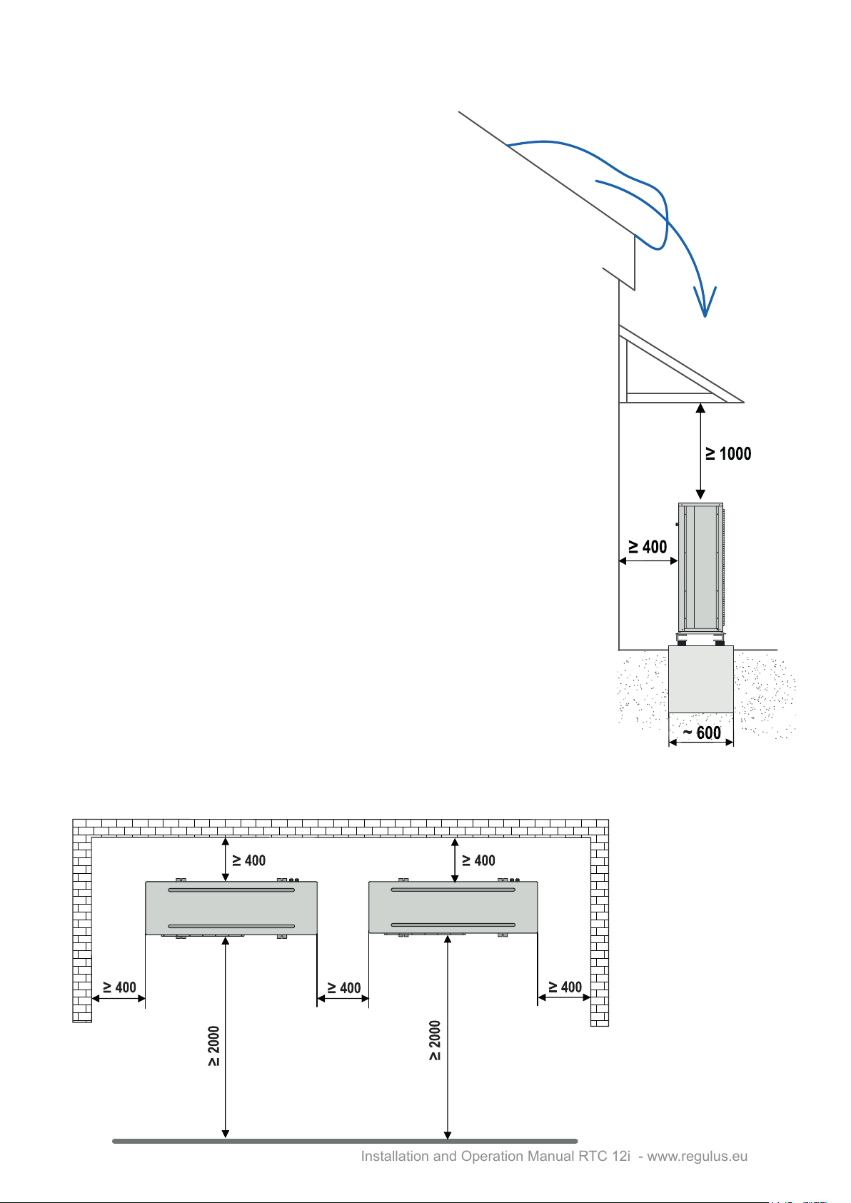
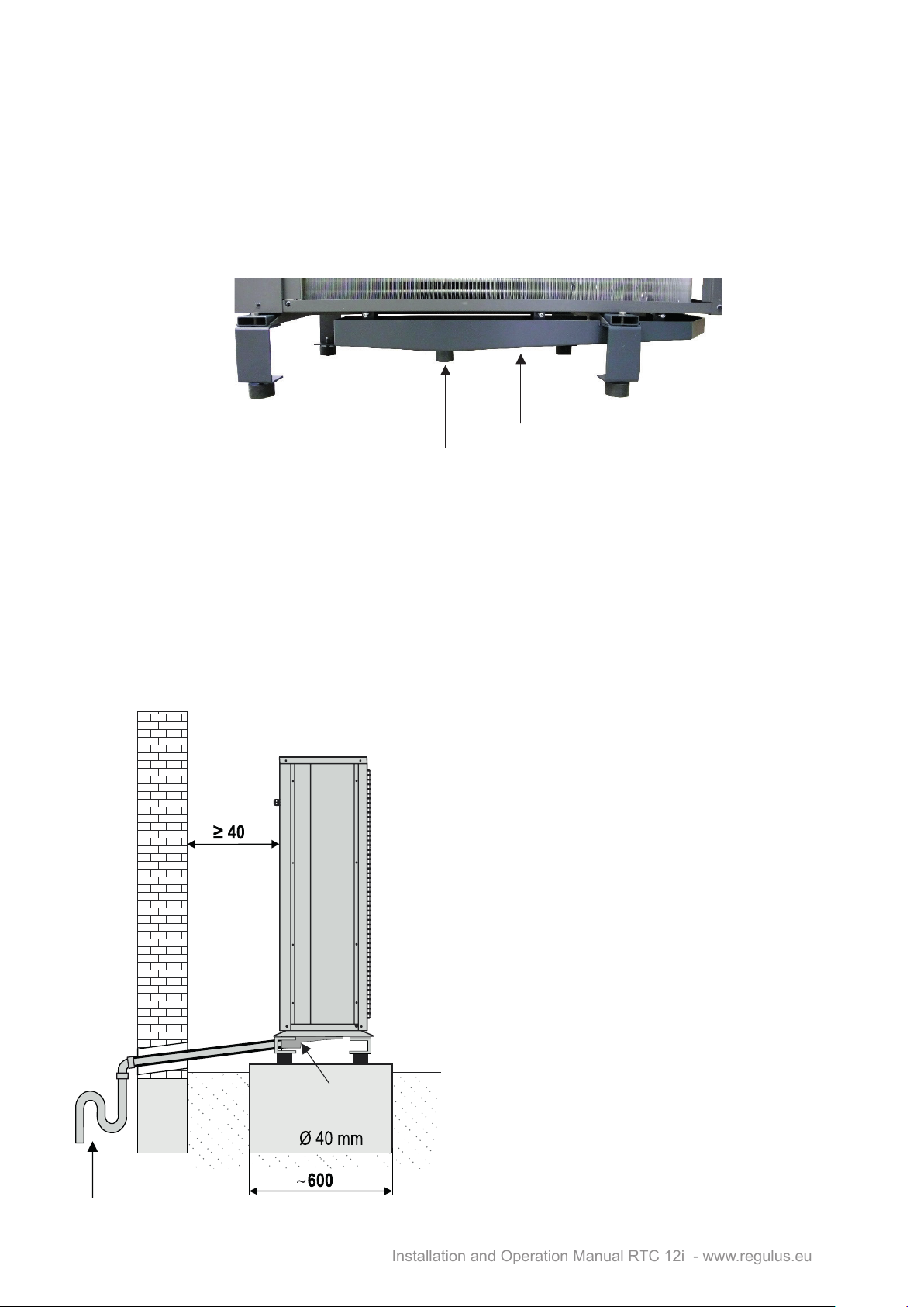
The heat pump is part of the energy system of the house. The correct design of a heat pump
depends on the energy needs of the building and should be carried out by a specialist. These
methods of connection are the most commonly used and serve as a basis for the project. If project
documentation exists, follow it.
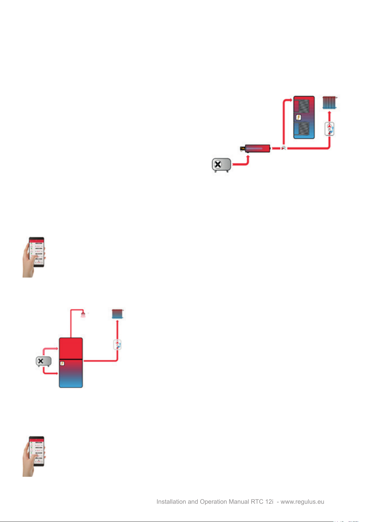
2.1. Direct connection to a heating system, DHW heating in a hot water storage tank
The accessory is represented by an additional heat
source in the form of an in line heater (code 16166)
equipped with an electric heating element of up to 7.5
kW output and an optional indirect heated hot water
storage tank with a heat exchanger surface of min. 1.5
m2(e.g. Regulus RDC 300 – code 12759). The larger
the heat exchange area of the HW storage tank, the
faster the DHW heating will be and the heat pump will
be able to prepare hot water more economically, or it will
be able to heat DHW to a higher temperature.
Inthisdirectconnectiontotheheatingsystem,itisnecessarytokeeptheminimumowthrough
the heat pump at the level of min. 1335 l/h (0.37 l/s)withsucientheatsupplyfordefrosting,i.e.it
isnecessarytohaveapartoftheheatingsystemwithoutshut-ovalvesinstalled,e.g.thermostatic
valves. Approximately it is at least 5 radiators of normal size (e.g. 0.6 x 0.9 m), or at least 30 m2of
underoorheatingwithoutthepossibilitytobeshuto.
For system control, it is necessary to use an IR 14 RTC smart controller which controls the
entire heating and hot water system. It is equipped with an integrated web server permitting
control through a web browser, or via a smartphone or tablet with the IR Client application
(for Android and iOS).
2.2. Connection with a thermal store (combination with other renewable heat sources)
The accessories consist of a thermal store for heating only
(Regulus PS series), or a combination thermal store with
immersed DHW tank (Regulus DUO series), or a thermal store
with stainless steel tube DHW exchanger (Regulus HSK series).
TThis connection is suitable for combining a heat pump with
otherheatsources,suchasbiomassboilers,replaceinserts
and stoves with a hydronic heat exchanger, solar thermal
systems, solar photovoltaic systems, etc. The thermal store
shall be sized depending on the selected type and output of the
combined heat source, e.g. for combination with PV panels, the
total volume of the thermal store can be calculated using the
relationship 180 l / 1 kWp PV output. For example, for an array
of PV panels with a peak output of 5 kWp, the tank volume shall be 900 litres. Always have the size
and type of the thermal store determined by a specialist!
For system control, it is necessary to use an IR 14 RTC smart controller which controls the
entire heating and hot water system. It is equipped with an integrated web server permitting
control through a web browser, or via a smartphone or tablet with the IR Client application
(for Android and iOS).